EP0079550B1 - Projectile fuse with selection between direct and delayed ignition - Google Patents
Projectile fuse with selection between direct and delayed ignition Download PDFInfo
- Publication number
- EP0079550B1 EP0079550B1 EP82110232A EP82110232A EP0079550B1 EP 0079550 B1 EP0079550 B1 EP 0079550B1 EP 82110232 A EP82110232 A EP 82110232A EP 82110232 A EP82110232 A EP 82110232A EP 0079550 B1 EP0079550 B1 EP 0079550B1
- Authority
- EP
- European Patent Office
- Prior art keywords
- projectile
- ignition
- contact member
- explosive charge
- direct
- Prior art date
- Legal status (The legal status is an assumption and is not a legal conclusion. Google has not performed a legal analysis and makes no representation as to the accuracy of the status listed.)
- Expired
Links
- 230000003111 delayed effect Effects 0.000 title claims description 14
- 239000002360 explosive Substances 0.000 claims description 14
- 230000001419 dependent effect Effects 0.000 claims 1
- 230000001133 acceleration Effects 0.000 description 4
- 239000004020 conductor Substances 0.000 description 4
- 230000000694 effects Effects 0.000 description 2
- 238000010304 firing Methods 0.000 description 2
- 239000002184 metal Substances 0.000 description 2
- 238000005452 bending Methods 0.000 description 1
- 230000007423 decrease Effects 0.000 description 1
- 238000010586 diagram Methods 0.000 description 1
- 238000006073 displacement reaction Methods 0.000 description 1
- 239000012777 electrically insulating material Substances 0.000 description 1
- 238000000034 method Methods 0.000 description 1
- 238000012986 modification Methods 0.000 description 1
- 230000004048 modification Effects 0.000 description 1
- 229920003023 plastic Polymers 0.000 description 1
- 230000000717 retained effect Effects 0.000 description 1
- 238000005096 rolling process Methods 0.000 description 1
Images


Classifications
-
- F—MECHANICAL ENGINEERING; LIGHTING; HEATING; WEAPONS; BLASTING
- F42—AMMUNITION; BLASTING
- F42C—AMMUNITION FUZES; ARMING OR SAFETY MEANS THEREFOR
- F42C17/00—Fuze-setting apparatus
- F42C17/04—Fuze-setting apparatus for electric fuzes
-
- F—MECHANICAL ENGINEERING; LIGHTING; HEATING; WEAPONS; BLASTING
- F42—AMMUNITION; BLASTING
- F42C—AMMUNITION FUZES; ARMING OR SAFETY MEANS THEREFOR
- F42C19/00—Details of fuzes
- F42C19/06—Electric contact parts specially adapted for use with electric fuzes
-
- F—MECHANICAL ENGINEERING; LIGHTING; HEATING; WEAPONS; BLASTING
- F42—AMMUNITION; BLASTING
- F42C—AMMUNITION FUZES; ARMING OR SAFETY MEANS THEREFOR
- F42C9/00—Time fuzes; Combined time and percussion or pressure-actuated fuzes; Fuzes for timed self-destruction of ammunition
- F42C9/14—Double fuzes; Multiple fuzes
Definitions
- the present invention relates to an arrangement in a fuse for projectiles with explosive charge for changing 'over between direct and delayed ignition of the explosive charge, including an electrical contact member which can move in the lengthwise direction of the projectile and which under the influence of the accelerational forces effective on the projectile tends to move from an initial position in which it short-circuits an electrical igniter for the explosive charge to a second position where it interrupts the said short-circuit.
- a first ignition circuit for direct ignition usually consisting of an electrical circuit with an electrical igniter
- a second ignition circuit for delayed ignition e.g. consisting of a pyrotechnic ignition chain.
- the ignition circuit for delayed ignition is usually permanently connected in.
- the ignition circuit for direct ignition is normally inactivated by its electrical igniter being short-circuited.
- the change over to direct ignition is then made by interrupting the said short-circuit so that the electrical igniter is connected into the said electrical circuit.
- the PCT document WO 7 900 792 discloses a projectile fuse with selection between direct and delayed ignition, wherein an electrical contact member in the shape of a ball can move in the lengthwise direction of the projectile under the influence of the acceleration forces from an initial position in which it short circuits an electrical igniter, to a second position where it interrupts the short-circuit.
- the known fuse is disadvantageous, since the position and movement of the rolling ball cannot always be controlled in a safe way.
- the aim of the present invention is to provide a more reliable arrangement for changing over between delayed and direct ignition, where the position and movement of electrical contact member can be controlled in a more reliable way.
- This objective is achieved in that the arrangement in accordance with the invention has been given the characteristics described in claim 1.
- the locking device With a first angular position of the projectile, the locking device adopts such a position that it prevents the electrical contact member from moving from the first to the second position, so that the electrical igniter remains short-circuited and delayed ignition of the explosive charge takes place when the projectile impacts against a target.
- the locking device drops down so that as a result of the accelerational forces the contact member can move to the second position and is retained there by the detent member so that the short- circuiting of the electrical igniter is interrupted, i.e. so that direct ignition of the explosive charge takes place on impact.
- the direction of firing of the projectile is indicated in the diagrams by an arrow S.
- FIG. 1 shows schematically a fuse 1 which is designed to be screwed into a projectile body which is not illustrated.
- the ignition circuit for direct ignition comprises an electrical circuit with a supply source 2, e.g. a piezoelectrical generator, the positive pole of which is connected via a conductor 3 with an input connection 4 on the change over device in accordance with the invention which is generally designated as 5.
- the change over arrangement 5 has an output connection which comprises a moveable contact member in the form of a piston 6 which on one side is connected with the input connection 4 and on the other side with the body of the fuse, which in figure 1 is indicated by the symbol for earth.
- An electrical igniter 7 is connected between the conductor 3 and the body of the fuse 1.
- the negative pole of the supply source 2 is also connected to the body of the fuse, so that this serves as the return conductor in the ignition circuit.
- the method of igniting an explosive charge by means of an electrical igniter is generally known and employed, so that it has not been described here. For the same reason it has not been regarded as necessary to indicate the location of the explosive charge on the drawing.
- the ignition circuit for delayed ignition is not shown on the drawing. This can for example comprise in a known manner a pyrotechnic ignition chain with delay unit which is initiated mechanically when the projectile impacts against a target.
- the change over arrangement 5 comprises a housing, resembling a platform, consisting of two round plates 5a and 5b, which are joined together, made from an electrically insulating material, e.g. transparent plastic.
- the centre axis of the platform-like housing 5 is orientated at right angles to the longitudinal axis of the projectile.
- a circular contact metal plate 8 having a cut out tongue which rests resiliently against the conductor 3 and forms the said input connection 4 in the electrical ignition circuit.
- the diameter of the plate 8 is somewhat less than that of the housing 5 and the plate is located at some distance from the body of the fuse 1 so as to be insulated from the latter.
- the piston 6 comprises a plate which is bent into L-shape which under the effect of the acceleration forces imposed on the projectile can move rearwards against the effect of a spring 9 in a channel 10 which runs parallel with the longitudinal axis of the projectile and is incorporated in the housing 5.
- the longer arm of the L-shaped piston 6 extends in the longitudinal direction of channel 10 whilst its shorter arm 6a, located furthest to the rear, is bent at a right angle. Hence the rear portion of channel 10 is enlarged so as to permit the displacement of the piston 6.
- the longer arm of piston 6 is provided with an upwardly-folded tongue 11, the function of which will be described later.
- a recess 12 is formed in the piston 6, the function of which will also be described later.
- the housing 5 also contains a channel 13, which is at right angles to channel 10 and proceeds straight across the recess 12, in which channel a locking member in the form of a pin 14 is displaceably arranged.
- the channel 13 has a dimension somewhat greater than that of the pin 14 so that this pin can be moved easily inside channel 13.
- the task of the locking member 14 is, with a first angular position of the projectile, to interact with the tongue 11 so as to prevent the piston 6 moving from the piston illustrated in figure 2.
- the pin 14 at some slight distance d from the tongue 11 so that the movement of the pin 14 in channel 13 is not impeded.
- the piston 6 can then move along the distance d until the tongue 11 is stopped by pin 14, as shown in figure 9.
- the acceleration decreases the piston 6 reverts to the position shown in figure 6 under the influence of the spring 9.
- the metal contact plate 8 is provided with an L-shaped tongue 15 which when the projectile is at rest is held by spring force against one face of the piston 6.
- the firer wishes to set up delayed ignition of the explosive charge, he rotates the projectile through 180°C around its longitudinal axis. As a result the pin 14 drops down into the other end of channel 13, see figure 6, so that it is now located in the path of tongue 11.
- the piston 6 travels the distance d until the tongue 11 knocks against the pin 14, see figure 9, so that the piston 6 is prevented from moving further.
- the piston 6 reverts to the position illustrated in figure 6 under the force of spring 9.
- the piston 6 remains in contact with the body of the fuse, i.e. the electrical igniter 7 remains short-circuited, so that delayed ignition of the explosive charge takes place via the ignition circuit for delayed ignition, which is not illustrated.
- the pin 14 can be replaced by a ball or an arrangement which slides along a rail.
Landscapes
- Engineering & Computer Science (AREA)
- General Engineering & Computer Science (AREA)
- Air Bags (AREA)
- Toys (AREA)
- Catching Or Destruction (AREA)
- Compositions Of Oxide Ceramics (AREA)
- Portable Nailing Machines And Staplers (AREA)
Description
- The present invention relates to an arrangement in a fuse for projectiles with explosive charge for changing 'over between direct and delayed ignition of the explosive charge, including an electrical contact member which can move in the lengthwise direction of the projectile and which under the influence of the accelerational forces effective on the projectile tends to move from an initial position in which it short-circuits an electrical igniter for the explosive charge to a second position where it interrupts the said short-circuit.
- In such an arrangement there are normally two separate ignition circuits, a first ignition circuit for direct ignition, usually consisting of an electrical circuit with an electrical igniter, and a second ignition circuit for delayed ignition, e.g. consisting of a pyrotechnic ignition chain.
- The ignition circuit for delayed ignition is usually permanently connected in. The ignition circuit for direct ignition is normally inactivated by its electrical igniter being short-circuited. The change over to direct ignition is then made by interrupting the said short-circuit so that the electrical igniter is connected into the said electrical circuit.
- The PCT
document WO 7 900 792 discloses a projectile fuse with selection between direct and delayed ignition, wherein an electrical contact member in the shape of a ball can move in the lengthwise direction of the projectile under the influence of the acceleration forces from an initial position in which it short circuits an electrical igniter, to a second position where it interrupts the short-circuit. The known fuse is disadvantageous, since the position and movement of the rolling ball cannot always be controlled in a safe way. - Consequently the aim of the present invention is to provide a more reliable arrangement for changing over between delayed and direct ignition, where the position and movement of electrical contact member can be controlled in a more reliable way. This objective is achieved in that the arrangement in accordance with the invention has been given the characteristics described in
claim 1. - By means of the locking device according to the invention it has become possible for the firer, before firing the projectile, to choose in a very reliable way between delayed or direct ignition merely by selecting an appropriate angular position of the projectile in the barrel.
- With a first angular position of the projectile, the locking device adopts such a position that it prevents the electrical contact member from moving from the first to the second position, so that the electrical igniter remains short-circuited and delayed ignition of the explosive charge takes place when the projectile impacts against a target.
- With a second angular position of the projectile the locking device drops down so that as a result of the accelerational forces the contact member can move to the second position and is retained there by the detent member so that the short- circuiting of the electrical igniter is interrupted, i.e. so that direct ignition of the explosive charge takes place on impact.
- The invention will be described in greater detail in the following by reference to the appended drawings which illustrate a preferred embodiment of the invention.
-
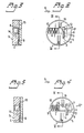
- Figure 1 shows in perspective an X-ray view of a fuse with an arrangement in accordance with the invention.
- Figure 2 shows an X-ray view from the side of the arrangement illustrated in figure 1, with a first angular position of the projectile in the at-rest position.
- Figure 3 shows the section along the line III-III in figure 2.
- Figure 4 shows the same X-ray view as in figure 2, but during the ejection phase of the projectile.
- Figure 5 illustrates a section along the line V-V in figure 4.
- Figure 6 shows the same X-ray view as in figure 2, but with the projectile rotated 180° around its axis.
- Figures 7 and 8 show a section along the line VII and VIII respectively in figure 6.
- Figure 9 shows the same X-ray view as in figure 6, but during the ejection phase of the projectile.
- The direction of firing of the projectile is indicated in the diagrams by an arrow S.
- Figure 1 shows schematically a
fuse 1 which is designed to be screwed into a projectile body which is not illustrated. The ignition circuit for direct ignition comprises an electrical circuit with asupply source 2, e.g. a piezoelectrical generator, the positive pole of which is connected via aconductor 3 with aninput connection 4 on the change over device in accordance with the invention which is generally designated as 5. The change overarrangement 5 has an output connection which comprises a moveable contact member in the form of apiston 6 which on one side is connected with theinput connection 4 and on the other side with the body of the fuse, which in figure 1 is indicated by the symbol for earth. - An
electrical igniter 7, indicated schematically, is connected between theconductor 3 and the body of thefuse 1. The negative pole of thesupply source 2 is also connected to the body of the fuse, so that this serves as the return conductor in the ignition circuit. The method of igniting an explosive charge by means of an electrical igniter is generally known and employed, so that it has not been described here. For the same reason it has not been regarded as necessary to indicate the location of the explosive charge on the drawing. - The ignition circuit for delayed ignition is not shown on the drawing. This can for example comprise in a known manner a pyrotechnic ignition chain with delay unit which is initiated mechanically when the projectile impacts against a target.
- The change over
arrangement 5 comprises a housing, resembling a platform, consisting of tworound plates like housing 5 is orientated at right angles to the longitudinal axis of the projectile. - Between the
plates contact metal plate 8 having a cut out tongue which rests resiliently against theconductor 3 and forms the saidinput connection 4 in the electrical ignition circuit. The diameter of theplate 8 is somewhat less than that of thehousing 5 and the plate is located at some distance from the body of thefuse 1 so as to be insulated from the latter. - The
piston 6 comprises a plate which is bent into L-shape which under the effect of the acceleration forces imposed on the projectile can move rearwards against the effect of aspring 9 in achannel 10 which runs parallel with the longitudinal axis of the projectile and is incorporated in thehousing 5. - The longer arm of the L-
shaped piston 6 extends in the longitudinal direction ofchannel 10 whilst itsshorter arm 6a, located furthest to the rear, is bent at a right angle. Hence the rear portion ofchannel 10 is enlarged so as to permit the displacement of thepiston 6. - The longer arm of
piston 6 is provided with an upwardly-foldedtongue 11, the function of which will be described later. By bending thetongue 11 upwards arecess 12 is formed in thepiston 6, the function of which will also be described later. - The
housing 5 also contains achannel 13, which is at right angles tochannel 10 and proceeds straight across therecess 12, in which channel a locking member in the form of apin 14 is displaceably arranged. Thechannel 13 has a dimension somewhat greater than that of thepin 14 so that this pin can be moved easily insidechannel 13. - The task of the
locking member 14 is, with a first angular position of the projectile, to interact with thetongue 11 so as to prevent thepiston 6 moving from the piston illustrated in figure 2. In a practical embodiment, as shown inter alia by figure 6, it is here appropriate to have thepin 14 at some slight distance d from thetongue 11 so that the movement of thepin 14 inchannel 13 is not impeded. When accelerational forces occur thepiston 6 can then move along the distance d until thetongue 11 is stopped bypin 14, as shown in figure 9. When the acceleration decreases thepiston 6 reverts to the position shown in figure 6 under the influence of thespring 9. - The
metal contact plate 8 is provided with an L-shaped tongue 15 which when the projectile is at rest is held by spring force against one face of thepiston 6. - The function of the change over
arrangement 5 is as follows: - If the firer wishes to set up direct ignition of the explosive charge, he orientates the projectile so that the
pin 14 drops under its own weight down into one position inchannel 13, illustrated in figures 1 and 2. During ejection of the projectile accelerational forces prevail which move thepiston 6 to the rear. The detent member (the pin 14) does not prevent the movement of thepiston 6, because thetongue 11 is not held by thepin 14. When thepiston 6 has moved so far to the rear that thetongue 15 is in the centre of therecess 12 inpiston 6, thetongue 15 snaps into therecess 12 so that thepiston 6 is locked in this position (see figures 4 and 5). The electrical contact between thepiston 6 and the body of thefuse 1 is now broken, i.e. thesupply source 2 is now connected with theelectrical igniter 7 so that direct ignition of the explosive charge, which is not illustrated, occurs when the projectile hits it target. - If on the other hand the firer wishes to set up delayed ignition of the explosive charge, he rotates the projectile through 180°C around its longitudinal axis. As a result the
pin 14 drops down into the other end ofchannel 13, see figure 6, so that it is now located in the path oftongue 11. When the projectile is ejected thepiston 6 travels the distance d until thetongue 11 knocks against thepin 14, see figure 9, so that thepiston 6 is prevented from moving further. As soon as acceleration ceases thepiston 6 reverts to the position illustrated in figure 6 under the force ofspring 9. By this means thepiston 6 remains in contact with the body of the fuse, i.e. theelectrical igniter 7 remains short-circuited, so that delayed ignition of the explosive charge takes place via the ignition circuit for delayed ignition, which is not illustrated. - It is apparent that the firer, when choosing between direct or delayed ignition, must hold the projectile more or less in a horizontal position in order to enable the
pin 14 to drop in thechannel 13. - In accordance with a modified embodiment of the invention the
pin 14 can be replaced by a ball or an arrangement which slides along a rail. - The invention is not restricted to the embodiments illustrated and described, a large number of modifications thereof being feasible within the framework of the appended claims.
Claims (2)
Applications Claiming Priority (2)
| Application Number | Priority Date | Filing Date | Title |
|---|---|---|---|
| SE8106780 | 1981-11-16 | ||
| SE8106780A SE443447B (en) | 1981-11-16 | 1981-11-16 | DEVICE IN A TENDROR FOR PROJECTIL WITH EXPLOSIVE CHARGING FOR DIFFERENCE BETWEEN DIRECT AND DISTURBED IGNITION OF THE EXPLOSIVE CHARGING |
Publications (3)
| Publication Number | Publication Date |
|---|---|
| EP0079550A2 EP0079550A2 (en) | 1983-05-25 |
| EP0079550A3 EP0079550A3 (en) | 1983-07-20 |
| EP0079550B1 true EP0079550B1 (en) | 1986-02-26 |
Family
ID=20345039
Family Applications (1)
| Application Number | Title | Priority Date | Filing Date |
|---|---|---|---|
| EP82110232A Expired EP0079550B1 (en) | 1981-11-16 | 1982-11-06 | Projectile fuse with selection between direct and delayed ignition |
Country Status (6)
| Country | Link |
|---|---|
| US (1) | US4515081A (en) |
| EP (1) | EP0079550B1 (en) |
| CA (1) | CA1207188A (en) |
| DE (1) | DE3269464D1 (en) |
| NO (1) | NO155072C (en) |
| SE (1) | SE443447B (en) |
Families Citing this family (1)
| Publication number | Priority date | Publication date | Assignee | Title |
|---|---|---|---|---|
| CN107982822B (en) * | 2017-12-29 | 2023-04-07 | 广州鼎飞航空科技有限公司 | Reliable device of unmanned aerial vehicle fire extinguishing bomb ignition |
Family Cites Families (13)
| Publication number | Priority date | Publication date | Assignee | Title |
|---|---|---|---|---|
| US2483555A (en) * | 1943-06-17 | 1949-10-04 | Harry J Nichols | Fuse |
| US2974598A (en) * | 1947-02-03 | 1961-03-14 | William B Mclean | Self destruction switch |
| US3086468A (en) * | 1957-12-20 | 1963-04-23 | Mountjoy Garrard | Angle sensitive switch |
| US3054870A (en) * | 1958-06-09 | 1962-09-18 | Wagoner Junior Billy | Variable sensitivity inertia switch |
| US3388667A (en) * | 1959-03-27 | 1968-06-18 | Navy Usa | Contact fuze |
| CH383836A (en) * | 1960-06-30 | 1964-10-31 | Oerlikon Buehrle Ag | Projectile that can be switched to instantaneous and delayed ignition |
| US3955508A (en) * | 1965-01-27 | 1976-05-11 | The United States Of America As Represented By The Secretary Of The Navy | Acceleration integrating switch |
| US3599572A (en) * | 1969-10-22 | 1971-08-17 | Avco Corp | Safing and arming system for a munition |
| US3780660A (en) * | 1971-02-23 | 1973-12-25 | Us Air Force | Multiple function safe and arm mechanism |
| US3771457A (en) * | 1972-11-13 | 1973-11-13 | Us Army | Multi-circuit safing and arming switch |
| US4029016A (en) * | 1976-06-29 | 1977-06-14 | The United States Of America As Represented By The Secretary Of The Army | Plural mode fuze |
| CH620765A5 (en) * | 1978-03-17 | 1980-12-15 | Zaugg Elektronik Ag | |
| US4230042A (en) * | 1978-07-26 | 1980-10-28 | Dragolyoub Popovitch | Point-detonating impact fuze |
-
1981
- 1981-11-16 SE SE8106780A patent/SE443447B/en not_active IP Right Cessation
-
1982
- 1982-11-06 EP EP82110232A patent/EP0079550B1/en not_active Expired
- 1982-11-06 DE DE8282110232T patent/DE3269464D1/en not_active Expired
- 1982-11-11 NO NO823777A patent/NO155072C/en unknown
- 1982-11-12 CA CA000415384A patent/CA1207188A/en not_active Expired
- 1982-11-16 US US06/442,155 patent/US4515081A/en not_active Expired - Fee Related
Also Published As
| Publication number | Publication date |
|---|---|
| SE443447B (en) | 1986-02-24 |
| NO155072B (en) | 1986-10-27 |
| CA1207188A (en) | 1986-07-08 |
| DE3269464D1 (en) | 1986-04-03 |
| EP0079550A2 (en) | 1983-05-25 |
| NO155072C (en) | 1987-02-04 |
| NO823777L (en) | 1983-05-18 |
| SE8106780L (en) | 1983-05-17 |
| US4515081A (en) | 1985-05-07 |
| EP0079550A3 (en) | 1983-07-20 |
Similar Documents
| Publication | Publication Date | Title |
|---|---|---|
| US4421030A (en) | In-line fuze concept for antiarmor tactical warheads | |
| US4606272A (en) | Initiation delay system for warheads with tandem mounted shaped charges | |
| NO951329L (en) | Piezoelectric spark plug system | |
| IL107769A (en) | Tandem charge warhead with piezoelectrical fuses | |
| US5033382A (en) | Piezoelectric fuse for projectile with safe and arm mechanism | |
| US3304864A (en) | Apparatus for firing an anti-vehicle ground-to-ground armor piercing explosive charge | |
| WO1986000979A1 (en) | Shaped charge projectile system | |
| US4739705A (en) | Arming and motor ignition device | |
| US5097765A (en) | Electric fuze with selectable modes | |
| US5147975A (en) | Remotely settable, multi-output, electronic time fuze and method of operation | |
| US2619905A (en) | Impact fuse for rocket projectiles | |
| EP0079550A2 (en) | Projectile fuse with selection between direct and delayed ignition | |
| US4217828A (en) | Safety device for fuses | |
| EP0307632A2 (en) | Safing and arming mechanism | |
| GB2234334A (en) | Active protective element | |
| SE502461C2 (en) | Method of projectile-forming explosive charges | |
| GB1500483A (en) | Missile or warhead for ground attack | |
| US4062290A (en) | Electrical fuze for projectiles | |
| US4606271A (en) | Fuse with a piercing head for a projectile | |
| GB2254404A (en) | Safety device for submunition projectile | |
| US4334475A (en) | Proximity fuses | |
| US3120187A (en) | Projectiles fitted with an electric generator of the inertia type | |
| RU2131581C1 (en) | Method of protection of warhead of tandem ammunition and tandem ammunition | |
| EP0605356B1 (en) | Self-destructive electronic fuse | |
| JPH03502599A (en) | Arrival tube with safety device on warhead |
Legal Events
| Date | Code | Title | Description |
|---|---|---|---|
| PUAI | Public reference made under article 153(3) epc to a published international application that has entered the european phase |
Free format text: ORIGINAL CODE: 0009012 |
|
| PUAL | Search report despatched |
Free format text: ORIGINAL CODE: 0009013 |
|
| 17P | Request for examination filed |
Effective date: 19821106 |
|
| AK | Designated contracting states |
Designated state(s): DE FR GB IT |
|
| AK | Designated contracting states |
Designated state(s): DE FR GB IT |
|
| RAP1 | Party data changed (applicant data changed or rights of an application transferred) |
Owner name: AFFAERSVERKET FFV |
|
| ITF | It: translation for a ep patent filed | ||
| GRAA | (expected) grant |
Free format text: ORIGINAL CODE: 0009210 |
|
| AK | Designated contracting states |
Designated state(s): DE FR GB IT |
|
| ET | Fr: translation filed | ||
| REF | Corresponds to: |
Ref document number: 3269464 Country of ref document: DE Date of ref document: 19860403 |
|
| PLBE | No opposition filed within time limit |
Free format text: ORIGINAL CODE: 0009261 |
|
| STAA | Information on the status of an ep patent application or granted ep patent |
Free format text: STATUS: NO OPPOSITION FILED WITHIN TIME LIMIT |
|
| 26N | No opposition filed | ||
| REG | Reference to a national code |
Ref country code: FR Ref legal event code: ST |
|
| REG | Reference to a national code |
Ref country code: FR Ref legal event code: AR |
|
| REG | Reference to a national code |
Ref country code: FR Ref legal event code: BR |
|
| ITTA | It: last paid annual fee | ||
| PGFP | Annual fee paid to national office [announced via postgrant information from national office to epo] |
Ref country code: GB Payment date: 19951027 Year of fee payment: 14 |
|
| PGFP | Annual fee paid to national office [announced via postgrant information from national office to epo] |
Ref country code: FR Payment date: 19951130 Year of fee payment: 14 |
|
| PGFP | Annual fee paid to national office [announced via postgrant information from national office to epo] |
Ref country code: DE Payment date: 19951228 Year of fee payment: 14 |
|
| PG25 | Lapsed in a contracting state [announced via postgrant information from national office to epo] |
Ref country code: GB Effective date: 19961106 |
|
| GBPC | Gb: european patent ceased through non-payment of renewal fee |
Effective date: 19961106 |
|
| PG25 | Lapsed in a contracting state [announced via postgrant information from national office to epo] |
Ref country code: FR Effective date: 19970731 |
|
| PG25 | Lapsed in a contracting state [announced via postgrant information from national office to epo] |
Ref country code: DE Effective date: 19970801 |
|
| REG | Reference to a national code |
Ref country code: FR Ref legal event code: ST |