EP0079357B1 - Drum for separation of a bulk material - Google Patents
Drum for separation of a bulk material Download PDFInfo
- Publication number
- EP0079357B1 EP0079357B1 EP82901556A EP82901556A EP0079357B1 EP 0079357 B1 EP0079357 B1 EP 0079357B1 EP 82901556 A EP82901556 A EP 82901556A EP 82901556 A EP82901556 A EP 82901556A EP 0079357 B1 EP0079357 B1 EP 0079357B1
- Authority
- EP
- European Patent Office
- Prior art keywords
- drum
- lifters
- fraction
- thread turns
- discharge aperture
- Prior art date
- Legal status (The legal status is an assumption and is not a legal conclusion. Google has not performed a legal analysis and makes no representation as to the accuracy of the status listed.)
- Expired
Links
- 239000013590 bulk material Substances 0.000 title claims abstract description 20
- 238000000926 separation method Methods 0.000 title claims abstract description 20
- 239000000463 material Substances 0.000 claims abstract description 10
- 230000004888 barrier function Effects 0.000 claims abstract description 4
- 239000002245 particle Substances 0.000 claims description 20
- 239000000725 suspension Substances 0.000 claims description 3
- 230000001133 acceleration Effects 0.000 claims description 2
- 230000001154 acute effect Effects 0.000 claims description 2
- 239000010902 straw Substances 0.000 description 11
- 238000010586 diagram Methods 0.000 description 2
- 238000009434 installation Methods 0.000 description 2
- 230000005540 biological transmission Effects 0.000 description 1
- 238000007599 discharging Methods 0.000 description 1
- 238000001035 drying Methods 0.000 description 1
- 230000000694 effects Effects 0.000 description 1
- 238000003306 harvesting Methods 0.000 description 1
- 239000010903 husk Substances 0.000 description 1
- 239000000203 mixture Substances 0.000 description 1
- 230000007704 transition Effects 0.000 description 1
Images
Classifications
-
- B—PERFORMING OPERATIONS; TRANSPORTING
- B07—SEPARATING SOLIDS FROM SOLIDS; SORTING
- B07B—SEPARATING SOLIDS FROM SOLIDS BY SIEVING, SCREENING, SIFTING OR BY USING GAS CURRENTS; SEPARATING BY OTHER DRY METHODS APPLICABLE TO BULK MATERIAL, e.g. LOOSE ARTICLES FIT TO BE HANDLED LIKE BULK MATERIAL
- B07B11/00—Arrangement of accessories in apparatus for separating solids from solids using gas currents
- B07B11/06—Feeding or discharging arrangements
-
- A—HUMAN NECESSITIES
- A01—AGRICULTURE; FORESTRY; ANIMAL HUSBANDRY; HUNTING; TRAPPING; FISHING
- A01F—PROCESSING OF HARVESTED PRODUCE; HAY OR STRAW PRESSES; DEVICES FOR STORING AGRICULTURAL OR HORTICULTURAL PRODUCE
- A01F12/00—Parts or details of threshing apparatus
- A01F12/44—Grain cleaners; Grain separators
- A01F12/442—Rotary cleaners
-
- B—PERFORMING OPERATIONS; TRANSPORTING
- B07—SEPARATING SOLIDS FROM SOLIDS; SORTING
- B07B—SEPARATING SOLIDS FROM SOLIDS BY SIEVING, SCREENING, SIFTING OR BY USING GAS CURRENTS; SEPARATING BY OTHER DRY METHODS APPLICABLE TO BULK MATERIAL, e.g. LOOSE ARTICLES FIT TO BE HANDLED LIKE BULK MATERIAL
- B07B4/00—Separating solids from solids by subjecting their mixture to gas currents
- B07B4/02—Separating solids from solids by subjecting their mixture to gas currents while the mixtures fall
- B07B4/06—Separating solids from solids by subjecting their mixture to gas currents while the mixtures fall using revolving drums
Definitions
- the invention relates to a drum having at least one section for separating a bulk material into a heavier and a ligherfraction. More particularly the invention relates to a drum which is designed to be rotated around its horizontal or possibly slightly inclined central axis at a certain speed and to be traversed by a flow of air having a certain flow velocity, besides which the drum has at least one discharge aperture for the heavier fraction and at least one discharge aperture for the lighter fraction located further on in the drum viewed in the direction of the air flow.
- the drum in at least one section thereof between the said discharge aperture for the heavier fraction and the said discharge aperture for the lighter fraction is provided with rearward-feeding transport members in the form of inwardly directed spirals fastened to the inside of the drum and arranged so that during rotation of the drum they transport material in the thread turns between the spirals to the rear towards the said discharge aperture for the heavier fraction, and also lifters for the bulk material arranged in all thread turns and designed as barriers against continued rearward feed of the bulk material, each of said lifters interconnecting two adjacent spirals.
- the invention relates to a drum having a section for separation of chopped harvested crops which contain a mixture of grains and lighter components, so that it is possible to obtain the grains separately and straw and other lighter components separately.
- the aim of the invention is to offer a modified, improved separation drum.
- one aim is to design the separation drum in such a way that the degree of separation and the capacity of the drum can be calculated mathematically and be predicted even on the drawing board, which is of decisive importance for optimising the dimensions of the installation and the design of detailed components, all with the aim of reducing plant costs and of being able to increase capacity whilst retaining good or improved separation of the more valuable heavier fraction.
- each of said lifters mentioned in the preamble forms an obtuse angle with the first of the two adjacent spirals as viewed in the direction of the air flow and un acute angle with the second of said two spirals, which lifters are arranged in groups along the said section around the inside of the drum, each group consisting of all of a plurality of lifters that lie along a circumferential line (I-XI) defined by a transverse section of the drum, and where in each such group a plurality of the thread turns, but not all, contain lifters, and that the axial distance (L) between at least the majority of adjacent circumferential lines (I-XI), i.e.
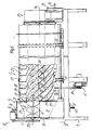
- Fig. 1 The installation shown in Fig. 1 consists as regards its main components of a chamber 1 which accommodates members for feeding in the bulk material which is to be separated and for discharging the heavier fraction of the bulk material, a separation drum 2 and a discharge chamber 3 for the lighter fraction of the bulk material.
- a foundation is designated as 4.
- chamber 1 The upper portion of chamber 1 is provided with a trough 5 with a semi-cylindrical bottom 6, a rear end 7, and a forward end 8 which is provided with a circular aperture 9.
- a feed aperture for the bulk material is designated as 10.
- the feed of the bulk material is symbolised by the dashed arrow 11.
- a discharge aperture for the heavier fraction is designated as 13, and the discharge of the heavier fraction is symbolised by the heavy arrow 14.
- the separation drum 2 is arranged to be rotated around its central axis 16 by means of a drive motor 17 via a V-belt transmission 18.
- the drum 2 rolls on a number of bogies 19 on the foundation 4.
- At its end which faces the chamber 1 the drum 2 communicates with the aperture 9 in the trough 5.
- a tube 20 leads into the interior of the drum 2 at a level above the centre line 16.
- a conical transition between the aperture 9 and tube 20 is designated as 21.
- a feeder screw 22 extends which has a somewhat larger diameter in the area of the trough 5 than in tube 20.
- the central axis 23 of feeder screw 22 is parallel with the central axis 16 of the drum.
- the tube 20 extends a distance into the drum 2 which is somewhat more than one third of the total length of drum 2.
- One end of tube 20 is designated as 24.
- the drum 2 At its far end the drum 2 is provided with a discharge aperture, not shown, for the lighter fraction.
- the discharge chamber 3 is connected to this farther discharge aperture. From the discharge chamber 3 the lighter fraction is arranged to be fed further through a discharge aperture 25.
- the discharge direction of the lighter fraction is symbolised by the unshaded arrow 26.
- the discharge chamber 3 does not comprise any part of the invention and hence this has not been illustrated in greater detail.
- the cylindrical separation drum 2 is clad internally with spirals 27 consisting of strips of plate, twisted in spiral fashion and directed radially inwards, which are welded onto the inside of drum 2.
- the thread turns between the spirals 27 have been designated as 28.
- the spirals 27 and thus also the thread turns 28 extend along the entire separation drum 2, i.e. from its left wall against chamber 1 to the discharge aperture, not shown, at the farther end of the drum against the discharge chamber 3.
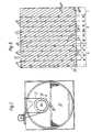
- the plan projection of the inside of the drum shown in Fig. 3 indicates the lifters 29 and 30 are located along a major portion of the length of the drum 2 in the thread turns 28 between adjacent spirals 27.
- the lifters 29 in a first section A have the shape of straight bars which have the same height as the spirals 27.
- Section A extends from the left wall of drum 2 close to chamber 1 up to the inner end 24 of the feed tube 20. It is indicated by Fig. 1 that the spirals 27 and bars 29 in zone A have a height which is only slightly less than the vertical distance between the top side of tube 20 and the inside of drum 2.
- the lifters 30 are longer than the height of the spirals 27, a point which is not indicated by the diagrams.
- the remainder of the separation drum 2 nearest the discharge aperture up to the discharge chamber 3 is designated as C.
- This section of the separation drum 2 has no lifters and is designated as the grain trap.
- the lifters 29 and 30 are distributed around the periphery of drum 2 in rows I, II, III ... XI with equal spacing between the rows and with an equal number of lifters 29 or 30 in each row.
- section A contains five rows I-V and section B has six rows VI-XI with an identical number of lifters (six) in each row.
- the lifters 29 or 30 are arranged in alternate thread turns 28 in each row I, II, III etc., but it is also feasible to locate the lifters in each third, each fourth, in two thread turns out of five etc. in each row of lifters I, II, III etc.
- v s the suspension velocity of the particle concerned, i.e. the lighter or the heavier particle, at a certain given particle size on the part of the heavier or the lighter fraction respectively which is the velocity where the air resistance in this ideal case is balanced precisely by the particle gravitational force.
- the trajectory in the vertical plane, Ly is governed by the shape of the lifters, speed of rotation etc., but is normally 85% of the diameter.
- the suspension velocity Vs of the particle changes with air humidity, air temperature and particle moisture content.
- the expression for the distance between the rows refers, as mentioned, to the horizontal average trajectory of a straw particle having a certain selected size and respectively for a normal grain or corresponding heavier fraction in the harvested crop.
- the angle of slope of the spirals 27 in the axial plane towards the drum is between 40° and 80°, preferably between 45° and 75°.
- the slope, i.e. the pitch of the threads can also vary along the length of the drum, and this can for example be utilised to optimise the function of the drum in various respects.
- the grain trap there are no lifters.
- the distance between the last row of lifters XI and the discharge aperture for the light fraction at the farther end of the drum is established in such a way that the majority of the straw is discharged directly through the ' discharge aperture at this end.
- the material which lands in the grain trap mainly some straw and other lighter particles but also some grain, is fed backwards and is subjected to renewed separation, which finally results in the straw again being fed towards the discharge aperture for the lighter fraction close to the discharge chamber 3, and the grains towards the chamber 12 in chamber 1. This means that only.a small portion of the grains end up in the grain trap C and that the majority of the grains are fed back extremely rapidly towards chamber 12 for further transport away through aperture 13.
- the sub-divisioning of the lifters 29, 30 into clearly distinct rows I, II, III ... IX facilitates the dimensioning of the drum 2. This should preferably be dimensioned for a certain type of crop, but to some extent it is possible to adjust the separation of other types of grain by means of the air flow.
- the invention can deviate from the description provided here.
- the lifters do not necessarily have to be arranged in rows in the same plane, but instead in groups where the lifters can be placed on either side of an assumed plane.
- the lifters in one group can continue directly into a next group in the form of continuous rails through the portion of the drum concerned, or even in such a way that the lifters overlap each other, all presupposing that with the definitions provided above.
- the lifters are not so designed that they totally block the thread turns, but merely a portion of the thread turns, or that they are provided with apertures or gaps permitting some of the crop to pass by in the thread turns.
Landscapes
- Life Sciences & Earth Sciences (AREA)
- Environmental Sciences (AREA)
- Combined Means For Separation Of Solids (AREA)
- Feeding Of Articles To Conveyors (AREA)
- Filling Or Emptying Of Bunkers, Hoppers, And Tanks (AREA)
- Separation, Recovery Or Treatment Of Waste Materials Containing Plastics (AREA)
Abstract
Description
- The invention relates to a drum having at least one section for separating a bulk material into a heavier and a ligherfraction. More particularly the invention relates to a drum which is designed to be rotated around its horizontal or possibly slightly inclined central axis at a certain speed and to be traversed by a flow of air having a certain flow velocity, besides which the drum has at least one discharge aperture for the heavier fraction and at least one discharge aperture for the lighter fraction located further on in the drum viewed in the direction of the air flow.
- Further the drum in at least one section thereof between the said discharge aperture for the heavier fraction and the said discharge aperture for the lighter fraction is provided with rearward-feeding transport members in the form of inwardly directed spirals fastened to the inside of the drum and arranged so that during rotation of the drum they transport material in the thread turns between the spirals to the rear towards the said discharge aperture for the heavier fraction, and also lifters for the bulk material arranged in all thread turns and designed as barriers against continued rearward feed of the bulk material, each of said lifters interconnecting two adjacent spirals. In particular the invention relates to a drum having a section for separation of chopped harvested crops which contain a mixture of grains and lighter components, so that it is possible to obtain the grains separately and straw and other lighter components separately.
- In Swedish patent applications 8000682-8, 8003989-4 and 8003990-2, filed by the same applicant, a description is given of equipment appertaining to the technical field described above. By means of these proposed inventions, equipment has been created for drying, threshing and separating a harvested crop which contains components of different types, in such a way that none of the components suffers damage, but instead can be kept for use in the most suitable manner. A very high degree of separation of the grain from the chopped harvest crop lighter components has also been achieved, which is a pre-requisite for good overall economics on the part of the plant.
- Through US-A-3 126 893 there is also known a combination cylinder type threshing machine and rotating separating drum which has a multiplicity of radially inwardly extending helically disposed wall portions arranged on the inside of the cylindrical wall thereof and open helical passages extending along the entire length of the rotary member. These passages are interrupted by a multiplicity of drum elements which extend across each of said passages forming in effect a pair of continuous longitudinally spaced-apart annular barriers around the inside of the drum members.
- The aim of the invention is to offer a modified, improved separation drum. In particular one aim is to design the separation drum in such a way that the degree of separation and the capacity of the drum can be calculated mathematically and be predicted even on the drawing board, which is of decisive importance for optimising the dimensions of the installation and the design of detailed components, all with the aim of reducing plant costs and of being able to increase capacity whilst retaining good or improved separation of the more valuable heavier fraction.
- These and other objectives can be achieved therein that the lifting surface of each of said lifters mentioned in the preamble forms an obtuse angle with the first of the two adjacent spirals as viewed in the direction of the air flow and un acute angle with the second of said two spirals, which lifters are arranged in groups along the said section around the inside of the drum, each group consisting of all of a plurality of lifters that lie along a circumferential line (I-XI) defined by a transverse section of the drum, and where in each such group a plurality of the thread turns, but not all, contain lifters, and that the axial distance (L) between at least the majority of adjacent circumferential lines (I-XI), i.e. the pitch between the said circumferential lines, is greater than the horizontal average transport distance (Lt) of the particles appertaining to the heavier fraction during the fall of these particles from the iifters down towards the bottom of the drum, whilst the said distance is less than the horizontal average transport distance (L1) due to the flow of air in the drum for particles appertaining to the lighter fraction, which can also be expressed as

- Further characteristics of the invention will be indicated by the patent claims and by the following description of a preferred embodiment.
- In the following description of a preferred embodiment reference will be made to the appended diagrams in which:
- Fig. 1 gives a side view of a separation plant with a separation drum in accordance with the invention, where the drum and a feed chamber have been shown partly in section so as to illustrate the interior of the drum and the feed device,
- Fig. 2 is an end view 11-11 in Fig. 1, and
- Fig. 3 is a plan projection of the inside of the drum.
- The installation shown in Fig. 1 consists as regards its main components of a chamber 1 which accommodates members for feeding in the bulk material which is to be separated and for discharging the heavier fraction of the bulk material, a separation drum 2 and a
discharge chamber 3 for the lighter fraction of the bulk material. A foundation is designated as 4. - The upper portion of chamber 1 is provided with a trough 5 with a semi-cylindrical bottom 6, a
rear end 7, and aforward end 8 which is provided with acircular aperture 9. A feed aperture for the bulk material is designated as 10. The feed of the bulk material is symbolised by thedashed arrow 11. Underneath the trough 6 there is achamber 12 for the separated heavier fraction of the bulk material. A discharge aperture for the heavier fraction is designated as 13, and the discharge of the heavier fraction is symbolised by the heavy arrow 14. In the vicinity ofchamber 12 there is anair intake 15 provided with a mesh. - The separation drum 2 is arranged to be rotated around its central axis 16 by means of a
drive motor 17 via a V-belt transmission 18. The drum 2 rolls on a number ofbogies 19 on the foundation 4. At its end which faces the chamber 1 the drum 2 communicates with theaperture 9 in the trough 5. Thus from trough 5 atube 20 leads into the interior of the drum 2 at a level above the centre line 16. A conical transition between theaperture 9 andtube 20 is designated as 21. Through the trough 5 and tube 20 afeeder screw 22 extends which has a somewhat larger diameter in the area of the trough 5 than intube 20. Thecentral axis 23 offeeder screw 22 is parallel with the central axis 16 of the drum. In accordance with the embodiment, thetube 20 extends a distance into the drum 2 which is somewhat more than one third of the total length of drum 2. One end oftube 20 is designated as 24. - At its far end the drum 2 is provided with a discharge aperture, not shown, for the lighter fraction. The
discharge chamber 3 is connected to this farther discharge aperture. From thedischarge chamber 3 the lighter fraction is arranged to be fed further through adischarge aperture 25. The discharge direction of the lighter fraction is symbolised by theunshaded arrow 26. Thedischarge chamber 3 does not comprise any part of the invention and hence this has not been illustrated in greater detail. - The cylindrical separation drum 2 is clad internally with
spirals 27 consisting of strips of plate, twisted in spiral fashion and directed radially inwards, which are welded onto the inside of drum 2. The thread turns between thespirals 27 have been designated as 28. Thespirals 27 and thus also the thread turns 28 extend along the entire separation drum 2, i.e. from its left wall against chamber 1 to the discharge aperture, not shown, at the farther end of the drum against thedischarge chamber 3. - The plan projection of the inside of the drum shown in Fig. 3 indicates the
lifters adjacent spirals 27. Thelifters 29 in a first section A have the shape of straight bars which have the same height as thespirals 27. Section A extends from the left wall of drum 2 close to chamber 1 up to theinner end 24 of thefeed tube 20. It is indicated by Fig. 1 that thespirals 27 andbars 29 in zone A have a height which is only slightly less than the vertical distance between the top side oftube 20 and the inside of drum 2. In the next section B which is somewhat longer than section A thelifters 30 are longer than the height of thespirals 27, a point which is not indicated by the diagrams. This gives a more efficient feed of the light fraction, and furthermore they are provided withlegs 31 in the vicinity of the spiral which, relative to thelifters 30, is located in the lee direction. The remainder of the separation drum 2 nearest the discharge aperture up to thedischarge chamber 3 is designated as C. This section of the separation drum 2 has no lifters and is designated as the grain trap. - As shown in Fig. 3, the
lifters lifters lifters - The distance L between rows I, II, III etc. is established so that


- VL=air velocity in m/s
- t= time of fall in seconds
- g=gravitational acceleration 9.81 m/s2
- vs=the suspension velocity of the particle concerned, i.e. the lighter or the heavier particle, at a certain given particle size on the part of the heavier or the lighter fraction respectively which is the velocity where the air resistance in this ideal case is balanced precisely by the particle gravitational force.
- a=1, where alternate thread turns in the groups are blocked by lifters, =2/3 when each third thread turn is blocked, =12 when each fourth thread turn is blocked, and so on for each fifth, for two thread turns out of five etc.
- The time of fall t is calculated from the expression:

- The trajectory in the vertical plane, Ly is governed by the shape of the lifters, speed of rotation etc., but is normally 85% of the diameter. The suspension velocity Vs of the particle changes with air humidity, air temperature and particle moisture content. With several particles there is a scatter around a horizontal average trajectory. With an increased volume of grain and straw, the scatter increases, whilst at the same time the average values for the trajectories of the grain and straw respectively in the horizontal plane approximate to each other. The expression for the distance between the rows

spirals 27 in the axial plane towards the drum is between 40° and 80°, preferably between 45° and 75°. The slope, i.e. the pitch of the threads, can also vary along the length of the drum, and this can for example be utilised to optimise the function of the drum in various respects. - Harvested crops in the form of grains mixed with chopped straw, husks and similar lighter particles are fed into the trough 5 through the aperture 10. From the trough 5 the mixed crop is passed by means of the
screw 22 throughtube 20 into the centre of drum 2. As a result of rotation of drum 2 the grains and straw are transported rearwards in thread turns 28. When some of the rows I-XI in Fig. 3 are reached the fairly mixed bulk material passes by thelifters lifters lifters shorter lifters 29 and somewhat more for the longer lifters 30). The expression "free diameter" signifies the diameter inside thespirals 27. The material which falls downwards from thelifters 
discharge chamber 3 will normally be several times greater than the rearward feed, which gives more effective separation whilst at the same time increasing drum capacity. - In the last section C, the grain trap, there are no lifters. The distance between the last row of lifters XI and the discharge aperture for the light fraction at the farther end of the drum is established in such a way that the majority of the straw is discharged directly through the' discharge aperture at this end. The material which lands in the grain trap, mainly some straw and other lighter particles but also some grain, is fed backwards and is subjected to renewed separation, which finally results in the straw again being fed towards the discharge aperture for the lighter fraction close to the
discharge chamber 3, and the grains towards thechamber 12 in chamber 1. This means that only.a small portion of the grains end up in the grain trap C and that the majority of the grains are fed back extremely rapidly towardschamber 12 for further transport away throughaperture 13. - The sub-divisioning of the
lifters - It should be evident that within the framework of the following patent claims the invention can deviate from the description provided here. Thus it is possible to envisage that the lifters do not necessarily have to be arranged in rows in the same plane, but instead in groups where the lifters can be placed on either side of an assumed plane. In this context it should be evident that the lifters in one group can continue directly into a next group in the form of continuous rails through the portion of the drum concerned, or even in such a way that the lifters overlap each other, all presupposing that

Claims (5)


Priority Applications (1)
| Application Number | Priority Date | Filing Date | Title |
|---|---|---|---|
| AT82901556T ATE23654T1 (en) | 1981-05-15 | 1982-05-07 | DRUM FOR SEPARATION OF LOOSE MATERIAL. |
Applications Claiming Priority (2)
| Application Number | Priority Date | Filing Date | Title |
|---|---|---|---|
| SE8103060A SE426348B (en) | 1981-05-15 | 1981-05-15 | DRUM FOR SEPARATION OF A MASSAGE GOOD |
| SE8103060 | 1981-05-15 |
Publications (2)
| Publication Number | Publication Date |
|---|---|
| EP0079357A1 EP0079357A1 (en) | 1983-05-25 |
| EP0079357B1 true EP0079357B1 (en) | 1986-11-20 |
Family
ID=20343841
Family Applications (1)
| Application Number | Title | Priority Date | Filing Date |
|---|---|---|---|
| EP82901556A Expired EP0079357B1 (en) | 1981-05-15 | 1982-05-07 | Drum for separation of a bulk material |
Country Status (7)
| Country | Link |
|---|---|
| US (1) | US4549660A (en) |
| EP (1) | EP0079357B1 (en) |
| AU (1) | AU545098B2 (en) |
| DE (1) | DE3274327D1 (en) |
| DK (1) | DK149206C (en) |
| SE (1) | SE426348B (en) |
| WO (1) | WO1982003963A1 (en) |
Families Citing this family (11)
| Publication number | Priority date | Publication date | Assignee | Title |
|---|---|---|---|---|
| US2650947A (en) * | 1950-03-24 | 1953-09-01 | Edison Inc Thomas A | Primary battery |
| US4611605A (en) * | 1984-08-29 | 1986-09-16 | Deere & Company | Axial flow rotary separator |
| SU1720601A1 (en) * | 1988-05-05 | 1992-03-23 | Латвийская сельскохозяйственная академия | Device for determination of livestock performance index and feed allowances |
| US5091077A (en) * | 1990-10-09 | 1992-02-25 | Williams Robert M | Trommel material air classifier |
| IT1402117B1 (en) * | 2010-07-29 | 2013-08-28 | Cassani | METHOD AND DEVICE FOR SEPARATING PARTICLES OF DIFFERENT SYNTHETIC MATERIALS |
| US8631923B1 (en) * | 2012-09-28 | 2014-01-21 | Asm Technology Singapore Pte Ltd | Device sorting apparatus |
| US9370780B2 (en) * | 2014-09-17 | 2016-06-21 | Shane T. Nolan | Scrap separation system and device |
| US9440262B2 (en) | 2014-11-07 | 2016-09-13 | Rec Silicon Inc | Apparatus and method for silicon powder management |
| US9333538B1 (en) * | 2015-02-26 | 2016-05-10 | American Biocarbon, LLC | Technologies for material separation |
| US9682404B1 (en) | 2016-05-05 | 2017-06-20 | Rec Silicon Inc | Method and apparatus for separating fine particulate material from a mixture of coarse particulate material and fine particulate material |
| US10287171B2 (en) | 2016-05-05 | 2019-05-14 | Rec Silicon Inc | Tumbling device for the separation of granular polysilicon and polysilicon powder |
Family Cites Families (7)
| Publication number | Priority date | Publication date | Assignee | Title |
|---|---|---|---|---|
| US3126893A (en) * | 1964-03-31 | Combination cylinder type threshing machine | ||
| US2577488A (en) * | 1947-11-24 | 1951-12-04 | Isaac L Stephenson | Grain separating drum |
| US3425423A (en) * | 1966-08-24 | 1969-02-04 | Ross B Mckenzie | Grain separator |
| US4018567A (en) * | 1973-05-14 | 1977-04-19 | James P. La Point, Jr. | Apparatus for separating the constituents of lead-acid storage batteries |
| JPS5725719Y2 (en) * | 1977-01-13 | 1982-06-04 | ||
| US4207177A (en) * | 1978-04-03 | 1980-06-10 | Block Philip M | Material sorter |
| US4187172A (en) * | 1978-08-30 | 1980-02-05 | Datsenko Nikolai M | Apparatus for the separation of trash from less heavy firm articles in a flow of liquid |
-
1981
- 1981-05-15 SE SE8103060A patent/SE426348B/en not_active IP Right Cessation
-
1982
- 1982-05-07 US US06/456,045 patent/US4549660A/en not_active Expired - Fee Related
- 1982-05-07 EP EP82901556A patent/EP0079357B1/en not_active Expired
- 1982-05-07 DE DE8282901556T patent/DE3274327D1/en not_active Expired
- 1982-05-07 AU AU84529/82A patent/AU545098B2/en not_active Ceased
- 1982-05-07 WO PCT/SE1982/000159 patent/WO1982003963A1/en not_active Ceased
-
1983
- 1983-01-14 DK DK14883A patent/DK149206C/en not_active IP Right Cessation
Also Published As
| Publication number | Publication date |
|---|---|
| DE3274327D1 (en) | 1987-01-08 |
| DK149206C (en) | 1986-08-11 |
| SE426348B (en) | 1983-01-17 |
| WO1982003963A1 (en) | 1982-11-25 |
| DK14883D0 (en) | 1983-01-14 |
| SE8103060L (en) | 1982-11-16 |
| DK14883A (en) | 1983-01-14 |
| AU8452982A (en) | 1982-12-07 |
| AU545098B2 (en) | 1985-06-27 |
| US4549660A (en) | 1985-10-29 |
| DK149206B (en) | 1986-03-17 |
| EP0079357A1 (en) | 1983-05-25 |
Similar Documents
| Publication | Publication Date | Title |
|---|---|---|
| AU599929B2 (en) | Unloading chute for a combine | |
| US6350197B1 (en) | Offset auger feed for a combine clean grain elevator | |
| US4457316A (en) | Axial flow combine with single distribution auger | |
| US4549660A (en) | Drum for separation of a bulk material | |
| US4489733A (en) | Axial flow combine | |
| US4180081A (en) | Distribution augers for an axial flow combine | |
| US3613691A (en) | Grain separator for combines | |
| CN107426968A (en) | The agriculture elevator supplied by multiple cross-helicity conveyers | |
| US4458697A (en) | Axial flow combine with vertically offset accelerator rolls | |
| AU641062B2 (en) | Air diverter for chaff removal in a combine | |
| US4535787A (en) | Axial flow combine | |
| US3126893A (en) | Combination cylinder type threshing machine | |
| US3963032A (en) | Threshing machine | |
| CN1042488C (en) | Four-in-one treater for grain threashing matter | |
| US801141A (en) | Grain-separator. | |
| CA1192865A (en) | Rotary drum with flow recycling means for separation of a bulk material into fractions | |
| US4716908A (en) | Combine | |
| SE421479B (en) | DRUM FOR SEPARATION OF MASS GOODS | |
| GB2051541A (en) | Combine harvesters | |
| US2284433A (en) | Grain pan for combines | |
| US3005551A (en) | Corn pitcher | |
| EP1849350A1 (en) | Clean grain and tailings conveying system for an agricultural combine | |
| US2275392A (en) | Grain threshing and separating machine | |
| US20250151645A1 (en) | Grain tank sump for agricultural vehicle | |
| US1500522A (en) | Grain separator |
Legal Events
| Date | Code | Title | Description |
|---|---|---|---|
| PUAI | Public reference made under article 153(3) epc to a published international application that has entered the european phase |
Free format text: ORIGINAL CODE: 0009012 |
|
| 17P | Request for examination filed |
Effective date: 19830131 |
|
| AK | Designated contracting states |
Designated state(s): AT BE CH DE FR GB LI LU NL SE |
|
| RAP1 | Party data changed (applicant data changed or rights of an application transferred) |
Owner name: SCANDINAVIAN FARMING AKTIEBOLAG |
|
| RAP1 | Party data changed (applicant data changed or rights of an application transferred) |
Owner name: RIPPELTON N.V. |
|
| GRAA | (expected) grant |
Free format text: ORIGINAL CODE: 0009210 |
|
| AK | Designated contracting states |
Kind code of ref document: B1 Designated state(s): AT BE CH DE FR GB LI LU NL SE |
|
| PG25 | Lapsed in a contracting state [announced via postgrant information from national office to epo] |
Ref country code: AT Effective date: 19861120 |
|
| REF | Corresponds to: |
Ref document number: 23654 Country of ref document: AT Date of ref document: 19861215 Kind code of ref document: T |
|
| REF | Corresponds to: |
Ref document number: 3274327 Country of ref document: DE Date of ref document: 19870108 |
|
| ET | Fr: translation filed | ||
| PLBE | No opposition filed within time limit |
Free format text: ORIGINAL CODE: 0009261 |
|
| STAA | Information on the status of an ep patent application or granted ep patent |
Free format text: STATUS: NO OPPOSITION FILED WITHIN TIME LIMIT |
|
| 26N | No opposition filed | ||
| REG | Reference to a national code |
Ref country code: GB Ref legal event code: 732 |
|
| REG | Reference to a national code |
Ref country code: CH Ref legal event code: PUE Owner name: DE ROTTERDAMSCHE DROOGDOK MAATSCHAPPIJ B.V. |
|
| NLS | Nl: assignments of ep-patents |
Owner name: DE ROTTERDAMSCHE DROOGDOK MAATSCHAPPIJ B.V. TE ROT |
|
| REG | Reference to a national code |
Ref country code: FR Ref legal event code: TP |
|
| PGFP | Annual fee paid to national office [announced via postgrant information from national office to epo] |
Ref country code: FR Payment date: 19930510 Year of fee payment: 12 |
|
| PGFP | Annual fee paid to national office [announced via postgrant information from national office to epo] |
Ref country code: SE Payment date: 19930517 Year of fee payment: 12 Ref country code: CH Payment date: 19930517 Year of fee payment: 12 |
|
| PGFP | Annual fee paid to national office [announced via postgrant information from national office to epo] |
Ref country code: NL Payment date: 19930531 Year of fee payment: 12 |
|
| PGFP | Annual fee paid to national office [announced via postgrant information from national office to epo] |
Ref country code: BE Payment date: 19930616 Year of fee payment: 12 |
|
| PGFP | Annual fee paid to national office [announced via postgrant information from national office to epo] |
Ref country code: LU Payment date: 19930702 Year of fee payment: 12 |
|
| EPTA | Lu: last paid annual fee | ||
| PG25 | Lapsed in a contracting state [announced via postgrant information from national office to epo] |
Ref country code: LU Free format text: LAPSE BECAUSE OF NON-PAYMENT OF DUE FEES Effective date: 19940507 |
|
| PG25 | Lapsed in a contracting state [announced via postgrant information from national office to epo] |
Ref country code: SE Effective date: 19940508 |
|
| PG25 | Lapsed in a contracting state [announced via postgrant information from national office to epo] |
Ref country code: LI Effective date: 19940531 Ref country code: CH Effective date: 19940531 Ref country code: BE Effective date: 19940531 |
|
| PGFP | Annual fee paid to national office [announced via postgrant information from national office to epo] |
Ref country code: GB Payment date: 19940902 Year of fee payment: 13 |
|
| PGFP | Annual fee paid to national office [announced via postgrant information from national office to epo] |
Ref country code: DE Payment date: 19940908 Year of fee payment: 13 |
|
| BERE | Be: lapsed |
Owner name: DE ROTTERDAMSCHE DROOGDOK MAATSCHAPPIJJ B.V. Effective date: 19940531 |
|
| PG25 | Lapsed in a contracting state [announced via postgrant information from national office to epo] |
Ref country code: NL Effective date: 19941201 |
|
| NLV4 | Nl: lapsed or anulled due to non-payment of the annual fee | ||
| EUG | Se: european patent has lapsed |
Ref document number: 82901556.9 Effective date: 19941210 |
|
| PG25 | Lapsed in a contracting state [announced via postgrant information from national office to epo] |
Ref country code: FR Effective date: 19950131 |
|
| REG | Reference to a national code |
Ref country code: CH Ref legal event code: PL |
|
| EUG | Se: european patent has lapsed |
Ref document number: 82901556.9 |
|
| REG | Reference to a national code |
Ref country code: FR Ref legal event code: ST |
|
| PG25 | Lapsed in a contracting state [announced via postgrant information from national office to epo] |
Ref country code: GB Effective date: 19950507 |
|
| GBPC | Gb: european patent ceased through non-payment of renewal fee |
Effective date: 19950507 |
|
| PG25 | Lapsed in a contracting state [announced via postgrant information from national office to epo] |
Ref country code: DE Effective date: 19960201 |