EP0078552A2 - Web coating apparatus and method - Google Patents
Web coating apparatus and method Download PDFInfo
- Publication number
- EP0078552A2 EP0078552A2 EP82110349A EP82110349A EP0078552A2 EP 0078552 A2 EP0078552 A2 EP 0078552A2 EP 82110349 A EP82110349 A EP 82110349A EP 82110349 A EP82110349 A EP 82110349A EP 0078552 A2 EP0078552 A2 EP 0078552A2
- Authority
- EP
- European Patent Office
- Prior art keywords
- pool
- web
- conduit
- coating
- branch conduits
- Prior art date
- Legal status (The legal status is an assumption and is not a legal conclusion. Google has not performed a legal analysis and makes no representation as to the accuracy of the status listed.)
- Withdrawn
Links
Images
Classifications
-
- B—PERFORMING OPERATIONS; TRANSPORTING
- B05—SPRAYING OR ATOMISING IN GENERAL; APPLYING FLUENT MATERIALS TO SURFACES, IN GENERAL
- B05C—APPARATUS FOR APPLYING FLUENT MATERIALS TO SURFACES, IN GENERAL
- B05C3/00—Apparatus in which the work is brought into contact with a bulk quantity of liquid or other fluent material
- B05C3/18—Apparatus in which the work is brought into contact with a bulk quantity of liquid or other fluent material only one side of the work coming into contact with the liquid or other fluent material
-
- G—PHYSICS
- G11—INFORMATION STORAGE
- G11B—INFORMATION STORAGE BASED ON RELATIVE MOVEMENT BETWEEN RECORD CARRIER AND TRANSDUCER
- G11B5/00—Recording by magnetisation or demagnetisation of a record carrier; Reproducing by magnetic means; Record carriers therefor
- G11B5/84—Processes or apparatus specially adapted for manufacturing record carriers
- G11B5/842—Coating a support with a liquid magnetic dispersion
Definitions
- This invention relates to web coating apparatus and methods.
- the invention has particular application to coating a moving web with a non-Newtonian coating liquid by passing the web into contact with a pool of such liquid, such that a portion of the pool is carried away as a thin coating on at least one side of the web.
- the substrate may comprise a wide web of biaxially oriented polyethylene terephthalate, acetates, polyolefins, or other conventional polymeric films which are approximately 0.0381mm (0.0015 inch) thick, and are from 304.8mm (12 inches) to 1219.2mm (48 inches) in width.
- the "magnetic ink" to be coated onto at least one side of such a substrate web may vary widely in formulation. However, in all known instances, this ink is a non-Newtonian liquid whose viscosity changes with shear rate. Such liquids have also been described as thixotropic and pseudoplastic fluids.
- the substrate may be routed into a reservoir of coating liquid, either as a free-running web, or while being guided by a backup roller, and air brushes or resilient wipers can be used thereafter to remove excess coating liquid from the substrate.
- the coating liquid is a consumable and must be replenished to the pool which is immediately at the substrate coating nip or interface.
- the present invention seeks to provide a replenishment means whose construction and arrangement ensures that the pool is of homogenous viscosity by ensuring that all liquid entering the pool experiences identical flow history or rheology.
- web coating apparatus including apparatus for feeding a non-Newtonian coating liquid from a liquid source through a conduit system to an elongated pool associated with an elongated web coating nip, and in which a travelling web passes through the nip in contact with the elongated pool and.emerges from the nip with a thin coating of liquid on one side thereof, is characterised in that the conduit system comprises an inlet conduit from the source and branch conduits to outlet ports spaced along the pool, the branch conduits being of smaller cross-sectional area than the conduit from which they branch, corresponding branch conduits being of substantially equal length and fluid shear characteristic, whereby each path from the inlet conduit to an individual port is of substantially equal length and fluid shear characteristic.
- a magnetic ink coating apparatus includes a 609.6mm (two-foot) long pool supplied from four equally spaced and equal size outlet ports, which receive their individual ink supplies from a single inlet port. From the inlet port a first conduit of uniform cross section extends towards the four outlet ports. This first conduit divides into two branch conduits of equal, uniform cross section, the cross section being one-half that of the first conduit. These two branch conduits extend equal distances before each divides into two branch conduits, for a total of four branch conduits which connect to the four outlet ports. In order to give equal flow rheology to all four liquid streams, these four branch conduits are of equal, uniform cross section (one-half that of the individual branch conduit) and are of equal length.
- US-A-4,038,442 deals with the coating of thixotropic liquids and shows the failure of the prior art to solve the problem of coating with different viscosity due to different flow history.
- a travelling web 12 is engaged around a backup roller 14, which is mounted for rotation about an axis 15, and is driven at a circumferential speed equal to the linear speed at which the web 12 is moving.
- the roller 14, for example, a circular cylinder, 152.4mm (6 inches) in diameter, and 349.25mm (13.75 inches) in axial length, and is made of highly polished metal.
- Guide rollers (not shown) direct the web 12 into contact with at least a substantial portion of the periphery of the backup roller 14.
- a stationary smoothing film 20 is positioned adjacent the web 12 around the periphery of the backup roller 14.
- the film 20 extends over a substantial portion of the web 12 which is in contact with the backup roller 14, and extends beyond such contact.
- Pressure generating means in the form of a pliable membrane 22 carried on a metal mandrel 23 and secured to a support 24, urges the film 20 into contact with the web 12 with a predetermined static force which is a function of the internal pressure within the membrane 22.
- the membrane 22 is tubular in shape, approximately 38.1mm (1.5 inches) in diameter, somewhat longer than the film 20 is wide.
- the tubular axis of the membrane 22 extends parallel to the axis of the roller 14 for _all positions of the membrane.
- Support 24 preferably allows for movement towards and away from backup roller 14 to vary the circumferential conformance length of membrane 22 to roller 14. For a fixed linear web speed, the greater the length of membrane conformance, the longer will be the coating zone, as measured in the direction of web travel, and the longer will be the residence time of the web in the coating zone.
- a conduit 26 communicates with the interior of membrane 22 and also with pressure regulating means 28 to supply a fluid, preferably air, to the interior of membrane 22.
- a fluid preferably air
- a metering pump (not shown) provides coating liquid through an input conduit 34 to a manifold 35 feeding a reservoir or pool 37 (Fig.2) of coating liquid at the confluence of web 12 and smoothing film 20.
- the metering pump is driven by a belt which is connected to roller 14.
- the desired amount of coating liquid is provided as a function of the speed of web movement.
- a constant rate of replenishment, from a fluid source is workable.
- the pool or reservoir 37 of coating liquid at the confluence of smoothing film 20 and web 12 provides a readily controllable coating on web 12 with, in essence, force generated by membrane 22 controlling the thickness of the coating, and the rate of resupply of the coating liquid controlling the width of the coating.
- the primary function of stationary smoothing film 20 is to provide an area of high shear force to the coating liquid. This in turn generates high hydrodynamic pressure, thus to spread and smooth the liquid coating material to a uniform thickness along the length of the web.
- a coated substrate is provided with liquid coating material evenly dispersed across the face of web 12 in a smooth and reproducible manner, and without a flow of surplus coating liquid at the trailing end of smoothing film 20.
- Uniform coating down the length of pool 37 (i.e. parallel to the axis of the roller 14 and across the length of the web 12), is dependent upon uniform viscosity down the length of the pool.
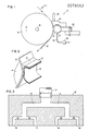
- the manifold 35 contains a conduit system, such as illustrated in Fig.3.
- the input conduit 34 branches into two identical conduits 40 and 41.
- Each of these two conduits branches into two identical conduits 42, 43 and 44, 45 leading to outlet ports 46, 47, 48 and 49 equally spaced down the length of pool 37.
- the conduits 40 and 41 are mirror images of each other, as are the conduits 42 and 43, and 44 and 45 and as is the whole conduit system.
- Fig.3 is a two-dimensional view of these conduits, and for simplicity all conduits are of equal depth dimension, i.e. the direction into the figure.
- the width of conduits 40 and 41 are equal to each other, and the sum of these widths equals the width of conduit 34.
- the width of conduits 42, 43, 44 and 45 are equal to each other, the sum of any two of these widths equals the width of conduit 40 (or 41), and the sum of all four of these widths equals the width of conduit 34.
- conduits 4G and 41 are equal to each other, and the length of conduits 42, 43, 44 and 45 are also equal to each other.
- conduit system of Fig.3 is exemplary of the present invention, and may be varied.
- the essence of this conduit system is that the branching conduits, whatever their number and whatever their geometric shape, be of substantially equal length, and subject their liquid flow to substantially equal fluid shear between inlet port 34 and pool 37. Stated in another way, all fluid should experience the same velocity of travel, the same mass flow rate, and the same shear rate, while travelling for the same time through the same distance. This uniform rheology ensures uniform viscosity and uniform flow at the coating nip.
- conduits of progressively increasing width and of progressively decreasing depth are used.
- the total conduit cross-sectional area at any plane of the conduit manifold normal to fluid flow remains constant, as the individual conduits thereof branch from one inlet conduit to the many outlet conduits.
- the length of the pool which is spanned by the sum of the outlet port widths may approach the length of the pool itself.
- the depths of conduits 42, 43, 44 and 45 are decreased at like amount for each conduit towards the ports 46, 47, 48 and 49, respectively.
- the widths of the conduit are correspondingly increased to maintain the cross-sectional areas. This - increase in width increases the length of the pool spanned by the sum of the widths of outlet ports 46, 47, 48 and 49.
Abstract
A wide travelling web is coated on one side thereof by passing the web through an elongated web coating nip in contact with an elongated pool of non-Newtonian coating liquid. The pool is repienished by a conduit manifold having one inlet conduit (34) and four outlet ports (46, 47, 48, 49). The outlet ports communicate directly with the pool. The inlet conduit divides into two branch conduits (40,41) of equal, uniform cross section, one-half that of the inlet conduit, and of equal length. Each branch conduit divides into two branch conduits, each leading to an outlet port. The four branch conduits (42, 43, 44, 45) are of equal, uniform cross section, one half that of each of the two branch conduits, and of equal length. Each of four liquid flow paths through the branch conduits subjects the coating liquid to substantially identical flow rheology because the paths are of substantially equal length and substantially equal fluid shear characteristic.
Description
- This invention relates to web coating apparatus and methods.
- The invention has particular application to coating a moving web with a non-Newtonian coating liquid by passing the web into contact with a pool of such liquid, such that a portion of the pool is carried away as a thin coating on at least one side of the web.
- Such coating has particular utility in the manufacture of flexible magnetic recording tape. In such a manufacturing process, the substrate may comprise a wide web of biaxially oriented polyethylene terephthalate, acetates, polyolefins, or other conventional polymeric films which are approximately 0.0381mm (0.0015 inch) thick, and are from 304.8mm (12 inches) to 1219.2mm (48 inches) in width. The "magnetic ink" to be coated onto at least one side of such a substrate web may vary widely in formulation. However, in all known instances, this ink is a non-Newtonian liquid whose viscosity changes with shear rate. Such liquids have also been described as thixotropic and pseudoplastic fluids.
- It is known that the thickness at which such liquids are coated onto such a web is dependent upon the viscosity of the liquid.
- A great number of means and apparatus exist which operate to coat such liquids onto a moving web. For example, an excess amount of liquid may be applied, with excess liquid thereafter being removed by operation of a doctor knife. Also, a roller may be used to conduct liquid from a pool to the passing substrate, or the liquid may be extruded in a thin layer directly onto the passing web. The substrate may be routed into a reservoir of coating liquid, either as a free-running web, or while being guided by a backup roller, and air brushes or resilient wipers can be used thereafter to remove excess coating liquid from the substrate.
- In all cases, the coating liquid is a consumable and must be replenished to the pool which is immediately at the substrate coating nip or interface.
- The present invention seeks to provide a replenishment means whose construction and arrangement ensures that the pool is of homogenous viscosity by ensuring that all liquid entering the pool experiences identical flow history or rheology.
- According to the invention, web coating apparatus including apparatus for feeding a non-Newtonian coating liquid from a liquid source through a conduit system to an elongated pool associated with an elongated web coating nip, and in which a travelling web passes through the nip in contact with the elongated pool and.emerges from the nip with a thin coating of liquid on one side thereof, is characterised in that the conduit system comprises an inlet conduit from the source and branch conduits to outlet ports spaced along the pool, the branch conduits being of smaller cross-sectional area than the conduit from which they branch, corresponding branch conduits being of substantially equal length and fluid shear characteristic, whereby each path from the inlet conduit to an individual port is of substantially equal length and fluid shear characteristic.
- Thus, in use, all liquid reaching the pool has passed through substantially identical length flow paths of substantially identical shear characteristic.
- In one embodiment of the invention, a magnetic ink coating apparatus includes a 609.6mm (two-foot) long pool supplied from four equally spaced and equal size outlet ports, which receive their individual ink supplies from a single inlet port. From the inlet port a first conduit of uniform cross section extends towards the four outlet ports. This first conduit divides into two branch conduits of equal, uniform cross section, the cross section being one-half that of the first conduit. These two branch conduits extend equal distances before each divides into two branch conduits, for a total of four branch conduits which connect to the four outlet ports. In order to give equal flow rheology to all four liquid streams, these four branch conduits are of equal, uniform cross section (one-half that of the individual branch conduit) and are of equal length.
- US-A-4,038,442 deals with the coating of thixotropic liquids and shows the failure of the prior art to solve the problem of coating with different viscosity due to different flow history.
- The scope of the invention is defined by the appended claims; and how it can be carried into effect is hereinafter particularly described with reference to'the accompanying drawings, in which :-
- FIGURE 1 is a simplified side view of a web coating apparatus according to the invention, incorporating non-Newtonian liquid feeding apparatus;
- FIGURE 2 shows the coating nip and location of the pool of coating liquid within the apparatus of Fig.l; and
- FIGURE 3 is a schematic sectional view of the conduit system which replenishes the pool of Fig.2 with coating liquid.
- The present invention will be described in a preferred application in web coating apparatus (Fig.1) such as-is described in EP-0003790, from which further details may be obtained.
- In the
coating apparatus 10, atravelling web 12 is engaged around abackup roller 14, which is mounted for rotation about anaxis 15, and is driven at a circumferential speed equal to the linear speed at which theweb 12 is moving. Theroller 14, for example, a circular cylinder, 152.4mm (6 inches) in diameter, and 349.25mm (13.75 inches) in axial length, and is made of highly polished metal. Guide rollers (not shown) direct theweb 12 into contact with at least a substantial portion of the periphery of thebackup roller 14. - A
stationary smoothing film 20 is positioned adjacent theweb 12 around the periphery of thebackup roller 14. Thefilm 20 extends over a substantial portion of theweb 12 which is in contact with thebackup roller 14, and extends beyond such contact. Pressure generating means in the form of apliable membrane 22 carried on ametal mandrel 23 and secured to asupport 24, urges thefilm 20 into contact with theweb 12 with a predetermined static force which is a function of the internal pressure within themembrane 22. Themembrane 22 is tubular in shape, approximately 38.1mm (1.5 inches) in diameter, somewhat longer than thefilm 20 is wide. The tubular axis of themembrane 22 extends parallel to the axis of theroller 14 for _all positions of the membrane.Support 24 preferably allows for movement towards and away frombackup roller 14 to vary the circumferential conformance length ofmembrane 22 toroller 14. For a fixed linear web speed, the greater the length of membrane conformance, the longer will be the coating zone, as measured in the direction of web travel, and the longer will be the residence time of the web in the coating zone. - A
conduit 26 communicates with the interior ofmembrane 22 and also with pressure regulating means 28 to supply a fluid, preferably air, to the interior ofmembrane 22. Thus, by regulating the internal pressure ofmembrane 22, the pressure generating means urges smoothingfilm 20 into contact withweb 12 at a desired static force which may be readily regulated by pressure regulating means 28. - A metering pump (not shown) provides coating liquid through an
input conduit 34 to amanifold 35 feeding a reservoir or pool 37 (Fig.2) of coating liquid at the confluence ofweb 12 andsmoothing film 20. Preferably, the metering pump is driven by a belt which is connected toroller 14. Thus, the desired amount of coating liquid is provided as a function of the speed of web movement. However, under steady state operating conditions, a constant rate of replenishment, from a fluid source, is workable. - The pool or
reservoir 37 of coating liquid at the confluence of smoothingfilm 20 andweb 12 provides a readily controllable coating onweb 12 with, in essence, force generated bymembrane 22 controlling the thickness of the coating, and the rate of resupply of the coating liquid controlling the width of the coating. The primary function ofstationary smoothing film 20 is to provide an area of high shear force to the coating liquid. This in turn generates high hydrodynamic pressure, thus to spread and smooth the liquid coating material to a uniform thickness along the length of the web. Asweb 12 emerges from smoothingfilm 20, a coated substrate is provided with liquid coating material evenly dispersed across the face ofweb 12 in a smooth and reproducible manner, and without a flow of surplus coating liquid at the trailing end ofsmoothing film 20. - Uniform coating down the length of pool 37 (i.e. parallel to the axis of the
roller 14 and across the length of the web 12), is dependent upon uniform viscosity down the length of the pool. - In order to achieve this uniform viscosity, the
manifold 35 contains a conduit system, such as illustrated in Fig.3. Theinput conduit 34 branches into twoidentical conduits identical conduits outlet ports pool 37. Theconduits conduits - Fig.3 is a two-dimensional view of these conduits, and for simplicity all conduits are of equal depth dimension, i.e. the direction into the figure. The width of
conduits conduit 34. In turn, the width ofconduits conduit 34. - In addition, the length of
conduits 4G and 41 are equal to each other, and the length ofconduits - In this manner, all coating
liquid entering pool 37 does so after having experienced similar flow history. - As will be appreciated, the conduit system of Fig.3 is exemplary of the present invention, and may be varied. The essence of this conduit system is that the branching conduits, whatever their number and whatever their geometric shape, be of substantially equal length, and subject their liquid flow to substantially equal fluid shear between
inlet port 34 andpool 37. Stated in another way, all fluid should experience the same velocity of travel, the same mass flow rate, and the same shear rate, while travelling for the same time through the same distance. This uniform rheology ensures uniform viscosity and uniform flow at the coating nip. - In another embodiment of the present invention, conduits of progressively increasing width and of progressively decreasing depth are used. In this embodiment, as in the previously described embodiment, the total conduit cross-sectional area at any plane of the conduit manifold normal to fluid flow remains constant, as the individual conduits thereof branch from one inlet conduit to the many outlet conduits. With this arrangement, the length of the pool which is spanned by the sum of the outlet port widths may approach the length of the pool itself. For example, in an arrangement similar to that of Fig.3, the depths of
conduits ports outlet ports - Whilst the invention has a particular and preferred application to the form of web coating apparatus, described in EP-0003790 referred to above, it is also applicable to other forms, such as described in US-A-3081191, US-A-3192895, US-A-4142010, DE-A-2756133, FR-A-2377235, GB-A-1540985, US-A-4143190 and US-A-4250211.
- While the invention has been particularly shown and described with reference to preferred embodiments thereof, it will be understood by those skilled in the art that various changes in form and details may be made therein without departing from the scope of the invention.
Claims (5)
1 Web coating apparatus including apparatus for feeding a non-Newtonian coating liquid from a liquid source through a conduit system to an elongated pool (37) associated with an elongated web coating nip, and in which a travelling web (12) passes through the nip in contact with the elongated pool (37) and emerges from the nip with a thin coating of the liquid on one side thereof, characterised in that the conduit system comprises an inlet conduit (34) from the source and branch conduits (40,41,42,43,44,45) to outlet ports (46,47,48,49) spaced along the pool, the branch conduits being of smaller cross-sectional area than the conduit from which they branch, corresponding branch conduits (40,41;42,43,44,45) being of substantially equally length and fluid shear characteristic, whereby each path from the inlet conduit to an individual port is of substantially equal length and fluid shear characteristic.
2 Apparatus according to claim 1, in which the inlet conduit (34) divides into a plurality of symmetrically disposed branch conduits (40,41), each of which divides into a plurality of symmetrically disposed branch conduits (42,43,44,45).
3 Apparatus according to claim 1 or 2, in which the utilization pool is elongated, the number of outlet ports is 2 N where N is an integer, and each division is into two branch conduits (40,41;42,43;44,45).
4 Apparatus according to claim 1, 2 or 3, in which each branch conduit is of uniform cross-section.
5 A method of coating a travelling web passing through an elongated pool (37) of non-Newtonian coating liquid, characterised by the use of apparatus according to claim 1, 2, 3 or 4, to feed liquid to the spaced outlet ports (46,47,48,49) communicating directly with the pool (37).
Applications Claiming Priority (2)
| Application Number | Priority Date | Filing Date | Title |
|---|---|---|---|
| US316367 | 1981-10-29 | ||
| US06/316,367 US4387124A (en) | 1981-10-29 | 1981-10-29 | Coating apparatus and method |
Related Parent Applications (2)
| Application Number | Title | Priority Date | Filing Date |
|---|---|---|---|
| EP82105014 Division | 1982-06-08 | ||
| EP82105014.3 Division | 1982-06-08 |
Publications (2)
| Publication Number | Publication Date |
|---|---|
| EP0078552A2 true EP0078552A2 (en) | 1983-05-11 |
| EP0078552A3 EP0078552A3 (en) | 1984-09-05 |
Family
ID=23228762
Family Applications (1)
| Application Number | Title | Priority Date | Filing Date |
|---|---|---|---|
| EP82110349A Withdrawn EP0078552A3 (en) | 1981-10-29 | 1982-06-08 | Web coating apparatus and method |
Country Status (3)
| Country | Link |
|---|---|
| US (1) | US4387124A (en) |
| EP (1) | EP0078552A3 (en) |
| JP (1) | JPS6057911B2 (en) |
Cited By (1)
| Publication number | Priority date | Publication date | Assignee | Title |
|---|---|---|---|---|
| AU581206B2 (en) * | 1984-02-17 | 1989-02-16 | Hoechst Aktiengesellschaft | The use of cephem compounds as immunomodulators |
Families Citing this family (18)
| Publication number | Priority date | Publication date | Assignee | Title |
|---|---|---|---|---|
| US4550681A (en) * | 1982-10-07 | 1985-11-05 | Johannes Zimmer | Applicator for uniformly distributing a flowable material over a receiving surface |
| US5037284A (en) * | 1986-12-17 | 1991-08-06 | Amoco Corporation | Hot-melt prepreg tow apparatus |
| EP0542635B1 (en) * | 1991-10-15 | 1999-06-09 | Eastman Kodak Company | Magnetic dispersion coating method and apparatus having high shear regions |
| US5632814A (en) * | 1992-02-27 | 1997-05-27 | Jagenberg Aktiengesellschaft | Device for applying a coating material to a running web |
| BR9406660A (en) * | 1993-05-27 | 1996-01-30 | Alcan Int Ltd | Apparatus and processes for coating on both sides of elongated strip articles |
| US5824157A (en) * | 1995-09-06 | 1998-10-20 | International Business Machines Corporation | Fluid jet impregnation |
| US5725668A (en) * | 1995-09-06 | 1998-03-10 | International Business Machines Corporation | Expandable fluid treatment device for tublar surface treatments |
| JPH09103732A (en) * | 1995-09-06 | 1997-04-22 | Internatl Business Mach Corp <Ibm> | Fluid feeder |
| US5754338A (en) * | 1996-04-01 | 1998-05-19 | Minnesota Mining And Manufacturing Company | Structured retroreflective sheeting having a rivet-like connection |
| US5882796A (en) * | 1996-04-01 | 1999-03-16 | Minnesota Mining And Manufacturing Company | Bonded structured retroreflective sheeting |
| US5910858A (en) * | 1996-04-01 | 1999-06-08 | Minnesota Mining And Manufacturing Company | Retroreflective sheeting with coated back surface |
| US5784197A (en) * | 1996-04-01 | 1998-07-21 | Minnesota Mining And Manufacturing Company | Ultra-flexible retroreflective sheeting with coated back surface |
| US6190454B1 (en) | 1997-06-19 | 2001-02-20 | Dean Robert Gary Anderson | Printer cartridge |
| US6786971B2 (en) | 1997-06-19 | 2004-09-07 | Dean Robert Gary Anderson | Method and apparatus for digital printing |
| US5972111A (en) * | 1997-06-19 | 1999-10-26 | Anderson; Dean Robert Gary | Metering device for paint for digital printing |
| US5944893A (en) * | 1997-06-19 | 1999-08-31 | Anderson; Dean Robert Gary | Metering device for paint for digital printing |
| WO1999000196A1 (en) | 1997-06-27 | 1999-01-07 | Alcan International Limited | Apparatus and method for coating sheet or strip articles |
| IT1319599B1 (en) * | 2000-12-20 | 2003-10-20 | Rosaldo Fare | MELT-BLOWN HEAD AND CONTROLLED FEEDING PROCEDURE FOR THE PRODUCTION OF POLYMERIC MATERIAL FIBRILLES |
Citations (6)
| Publication number | Priority date | Publication date | Assignee | Title |
|---|---|---|---|---|
| US3081191A (en) * | 1959-02-18 | 1963-03-12 | Mead Corp | Doctor blade |
| US3381336A (en) * | 1966-06-20 | 1968-05-07 | Stanley C. Wells | Melt spinning extrusion head system |
| FR2026848A1 (en) * | 1968-12-23 | 1970-09-25 | Ibm | |
| US4038442A (en) * | 1975-09-16 | 1977-07-26 | Fuji Photo Film Co., Ltd. | Method for coating |
| FR2377235A1 (en) * | 1977-01-17 | 1978-08-11 | Ibm | DEVICE FOR APPLYING A VISCOUS FLUID TO A SUBSTRATE |
| EP0003790A1 (en) * | 1978-02-23 | 1979-09-05 | International Business Machines Corporation | Device for coating a moving web |
Family Cites Families (4)
| Publication number | Priority date | Publication date | Assignee | Title |
|---|---|---|---|---|
| US3192895A (en) * | 1962-04-18 | 1965-07-06 | Time Inc | Web coating apparatus |
| US4324816A (en) * | 1975-05-22 | 1982-04-13 | Eastman Kodak Company | Method for forming a stripe by extrusion coating |
| US4143190A (en) * | 1977-01-27 | 1979-03-06 | Polaroid Corporation | Method and apparatus for coating webs |
| US4250211A (en) * | 1978-05-31 | 1981-02-10 | Consolidated Papers, Inc. | Paper coating method and apparatus |
-
1981
- 1981-10-29 US US06/316,367 patent/US4387124A/en not_active Expired - Fee Related
-
1982
- 1982-06-08 EP EP82110349A patent/EP0078552A3/en not_active Withdrawn
- 1982-07-16 JP JP57123088A patent/JPS6057911B2/en not_active Expired
Patent Citations (6)
| Publication number | Priority date | Publication date | Assignee | Title |
|---|---|---|---|---|
| US3081191A (en) * | 1959-02-18 | 1963-03-12 | Mead Corp | Doctor blade |
| US3381336A (en) * | 1966-06-20 | 1968-05-07 | Stanley C. Wells | Melt spinning extrusion head system |
| FR2026848A1 (en) * | 1968-12-23 | 1970-09-25 | Ibm | |
| US4038442A (en) * | 1975-09-16 | 1977-07-26 | Fuji Photo Film Co., Ltd. | Method for coating |
| FR2377235A1 (en) * | 1977-01-17 | 1978-08-11 | Ibm | DEVICE FOR APPLYING A VISCOUS FLUID TO A SUBSTRATE |
| EP0003790A1 (en) * | 1978-02-23 | 1979-09-05 | International Business Machines Corporation | Device for coating a moving web |
Cited By (1)
| Publication number | Priority date | Publication date | Assignee | Title |
|---|---|---|---|---|
| AU581206B2 (en) * | 1984-02-17 | 1989-02-16 | Hoechst Aktiengesellschaft | The use of cephem compounds as immunomodulators |
Also Published As
| Publication number | Publication date |
|---|---|
| EP0078552A3 (en) | 1984-09-05 |
| JPS5874421A (en) | 1983-05-04 |
| JPS6057911B2 (en) | 1985-12-17 |
| US4387124A (en) | 1983-06-07 |
Similar Documents
| Publication | Publication Date | Title |
|---|---|---|
| EP0078552A2 (en) | Web coating apparatus and method | |
| US4327130A (en) | Method and apparatus for forming a coating on both sides of a substrate | |
| US4442144A (en) | Method for forming a coating on a substrate | |
| US4871593A (en) | Method of streakless application of thin controlled fluid coatings and slot nozzle - roller coater applicator apparatus therefor | |
| US4299186A (en) | Method and apparatus for applying a viscous fluid to a substrate | |
| US4142010A (en) | Method for applying a viscous fluid to a substrate | |
| US4681062A (en) | Coating apparatus | |
| US2761417A (en) | Multiple coating apparatus | |
| US2901770A (en) | Extrusion apparatus and processes of extruding | |
| US4521457A (en) | Simultaneous formation and deposition of multiple ribbon-like streams | |
| JP2581975B2 (en) | Coating device | |
| US3627564A (en) | Method for coating a continuous web | |
| JPH0677711B2 (en) | Coating device | |
| JPS58104666A (en) | Coating apparatus | |
| US5348768A (en) | Method of applying a liquid coating to a flexible web | |
| US5028450A (en) | Method and apparatus for coating a thin film web by use of a plurality of pads facing an orifice | |
| US3573965A (en) | Multilayer coating method | |
| EP0534869A1 (en) | Liquid distribution system for photographic coating device | |
| US4345543A (en) | Apparatus for forming a coating on a substrate | |
| US5614260A (en) | Extrusion system with slide dies | |
| US4154879A (en) | Method and apparatus for coating webs with a plurality of liquid layers | |
| JP2934186B2 (en) | Application method | |
| US5376178A (en) | Coating apparatus | |
| US3302239A (en) | Die | |
| US5626671A (en) | Cross flow knife coater for applying a coating to a web |
Legal Events
| Date | Code | Title | Description |
|---|---|---|---|
| PUAI | Public reference made under article 153(3) epc to a published international application that has entered the european phase |
Free format text: ORIGINAL CODE: 0009012 |
|
| AK | Designated contracting states |
Designated state(s): DE FR GB |
|
| 17P | Request for examination filed |
Effective date: 19830408 |
|
| PUAL | Search report despatched |
Free format text: ORIGINAL CODE: 0009013 |
|
| RHK1 | Main classification (correction) |
Ipc: B05C 3/18 |
|
| AK | Designated contracting states |
Designated state(s): DE FR GB |
|
| STAA | Information on the status of an ep patent application or granted ep patent |
Free format text: STATUS: THE APPLICATION HAS BEEN WITHDRAWN |
|
| 18W | Application withdrawn |
Withdrawal date: 19850802 |
|
| RIN1 | Information on inventor provided before grant (corrected) |
Inventor name: PIPKIN, DAVID JOHN |