EP0077765A1 - Pneumatic controller - Google Patents
Pneumatic controller Download PDFInfo
- Publication number
- EP0077765A1 EP0077765A1 EP82870054A EP82870054A EP0077765A1 EP 0077765 A1 EP0077765 A1 EP 0077765A1 EP 82870054 A EP82870054 A EP 82870054A EP 82870054 A EP82870054 A EP 82870054A EP 0077765 A1 EP0077765 A1 EP 0077765A1
- Authority
- EP
- European Patent Office
- Prior art keywords
- flapper
- set point
- nozzle
- lever
- controller
- Prior art date
- Legal status (The legal status is an assumption and is not a legal conclusion. Google has not performed a legal analysis and makes no representation as to the accuracy of the status listed.)
- Granted
Links
Images


Classifications
-
- G—PHYSICS
- G05—CONTROLLING; REGULATING
- G05B—CONTROL OR REGULATING SYSTEMS IN GENERAL; FUNCTIONAL ELEMENTS OF SUCH SYSTEMS; MONITORING OR TESTING ARRANGEMENTS FOR SUCH SYSTEMS OR ELEMENTS
- G05B11/00—Automatic controllers
- G05B11/44—Automatic controllers pneumatic only
- G05B11/48—Automatic controllers pneumatic only with auxiliary power
- G05B11/50—Automatic controllers pneumatic only with auxiliary power in which the output signal represents a continuous function of the deviation from the desired value, i.e. continuous controllers
-
- Y—GENERAL TAGGING OF NEW TECHNOLOGICAL DEVELOPMENTS; GENERAL TAGGING OF CROSS-SECTIONAL TECHNOLOGIES SPANNING OVER SEVERAL SECTIONS OF THE IPC; TECHNICAL SUBJECTS COVERED BY FORMER USPC CROSS-REFERENCE ART COLLECTIONS [XRACs] AND DIGESTS
- Y10—TECHNICAL SUBJECTS COVERED BY FORMER USPC
- Y10T—TECHNICAL SUBJECTS COVERED BY FORMER US CLASSIFICATION
- Y10T137/00—Fluid handling
- Y10T137/2278—Pressure modulating relays or followers
- Y10T137/2409—With counter-balancing pressure feedback to the modulating device
- Y10T137/2452—With counter-counter balancing pressure feedback
Definitions
- This invention relates to process control apparatus, and more particularly, to an automatic, pneumatic controller of a process variable such as process pressure.
- a primary object of this invention is to provide an automatic, pneumatic controller of a process variable such as pressure which is improved over prior art controllers.
- objects of the invention are to provide a controller which is suitably rugged for field installation without signal conditioning accessories, facile of maintenance, and highly accurate.
- Another object of the invention is a controller in which set point adjustment, input and gain are structurally separated to eliminate artificial effect upon input and gain from set point adjustment.
- the invention is a controller of a process variable comprising a base, a nozzle, a set point lever, a flapper and a process lever.
- the nozzle is mounted on the set point lever, which is pivotably mounted on the base.
- the set point lever is for pivoting the nozzle about a set point and input axis in response to a set point adjustment.
- the flapper cooperates with the nozzle.
- the flapper is pivotably mounted on the base for pivotal movement about the set point and input axis.
- the process lever is connected to the flapper. It pivots the flapper about the set point and input axis in response to the process variable.
- the controller may or may not have feedback or gain mechanisms.
- the controller has the structure of the first aspect, and the flapper is pivotably mounted on the base for pivotal movement about a feedback axis, as well as the set point and input axis.
- the controller further comprises a feedback lever which is connected to the flapper. The feedback lever pivots the flapper about the feedback axis in response to feedback.
- the feedback axis is perpendicular to the input and set point axis and preferably passes through a common point.
- the nozzle is pivotably mounted on the set point lever and pivotable about a gain axis in response to a gain adjustment.
- the gain axis is generally mutually perpendicular with the feedback axis and the input and set point axis, and preferably all axes intersect at a common point.
- the nozzle and set point lever are structurally separated from the flapper, process lever and feedback lever, i.e., no mechanical linkage exists between the structure of the nozzle and set point lever, and the separate structure of the flapper, process lever and feedback lever.
- no artificial effect upon the process variable (input) or gain is caused by set point adjustment.
- the controller is ingeniously uncomplicated, readily suitable for field installation and accurate in use.
- the preferred embodiment of the present invention is a controller 10.
- the controller 10 is shown to be yoke-mounted on the actuator of a control valve 12.
- the vibration resistant design of the controller 10 makes it especially suitable for such mounting.
- the controller may also be mounted on a pipestand, on a wall or in a panel.
- the controller 10 controls process pressure in the pipeline (not shown) into which the valve 12 is positioned.
- a gauge 14 reports the pressure of a supply line 108 ( Figure 2) to the controller 10, and gauge 18 reports the pressure of a controller output conduit or line 20 ( Figure 2).
- a process pressure and set point display 22 reports the operator - adjusted set point and the process pressure.
- the gauges 14, 18 and display 22, along with all other components of the controller 10, are contained within a housing 24.
- the housing 24 is a plastic suitable to withstand corrosive environments, as found in chemical plants and on offshore oil platforms.
- the controller 10 finds use in applications throughout the power, chemical, oil and gas industries, wherever accurate process monitoring and control are required.
- the controller 10 operates by comparing the process pressure with the operator-adjusted set point, to deliver a pneumatic signal to a control element. This is accomplished so that process pressure changes toward the set point.
- the controller 10 may be modified for proportional-only control, proportional-plus-reset control, proportional-plus-reset-plus-rate control and differential gap control.
- the controller 10 includes an input element 26 such as a Bourdon tube ( Figure 4) connected by an input-element connecting link 28 to a process indicator such as pointer 30.
- the pointer 30 is mounted upon a dead shaft 32 secured to a base such as the housing 24. This mounting provides for pivoting movement of the pointer 30 about the shaft 32, in response to the driving action of the link 28.
- the pointer 30 cooperates with a scale 34 to report process pressure. Also cooperating with the scale 34 is a set point indicator and actuator such as pointer 36.
- the pointer 36 is, like the pointer 30, mounted on the dead shaft. Manual adjustment determines the location of the pointer 36. The manual adjustment determines the set point, i.e., the desired pressure of the process under control.
- the pointer 36 is linked to a nozzle 38 by a set point linkage 40. (The nozzle is hidden from view in Figure 4 by a cover 42.)
- a set point link 44 is connected to the pointer 36 and to a set point lever 46.
- the lever 46 includes a yoke 47 pivotably mounted at two spaced pivot points 49, 51 to the housing 24, for pivoting about a set point and input axis 48. Manual adjustment of the set point pointer 36 pivots the nozzle 38 through the action of the linkage 40.
- the pointer 30 and input connecting link 28 are linked to a flapper 50 by a process linkage 52.
- the linkage 52 is also hidden in Figure 4.
- a process beam 54 is connected to the pointer 30 and link 28, and to a first arm or process lever 56 of the flapper 50.
- the flapper 50 is mounted to the housing 24 for pivotal movement about the set point and input axis 48, and more specifically, a pivot point 58 ( Figure 3) along the axis 48.
- the pointer 30 and the flapper 50 are driven by the input element 26 through the connecting link 28 and through the linkage 52.
- the nozzle 38 and flapper 50 cooperate pneumatically in the usual fashion.
- the nozzle 38 has a flapper-cooperative opening 53 which is the outlet of a pneumatic line 60 connected by a relay 62 to the output line 20.
- Proximity of the nozzle 38 to the flapper 50 restricts flow through the nozzle 38 and establishes a pressure in the line 60 increased over that of the nozzle 38 without the flapper 50.
- Variation of the proximity of the nozzle 38 and flapper 50 causes a variation of the back pressure or nozzle pressure in the line 60. Movement of the nozzle 38 toward the flapper 50, and movement of the flapper 50 toward the nozzle 38, increase pressure in the line 60. Movement of the nozzle 38 and flapper 50 away from each other causes a pressure decrease. This pressure variation is the basis of the process control.
- the nozzle 38 is pivotably mounted on the set point lever 46, and a gain indicator and actuator such as a proportional band adjustment 64 is provided. Rotation of the adjustment 64 about a gain axis 66 causes pivoting of the nozzle 38 about the axis 66.
- the gain axis 66 is perpendicular to the set point and input axis 48.
- the flapper 50 is semicircular, and includes a planar nozzle cooperative surface 69 including two quadrants 68, 70.
- the flapper 50 is pivotable through positions in which the surface 69 parallels and intersects the axis 48.
- the quadrant 68 is a reverse action quadrant
- the quadrant 70 is a direct action quadrant.
- Gain is determined by the degree of movement of the nozzle 38 from a position of the nozzle 38 parallel to the axis 48 into either quadrant 68, 70.
- positioning of the nozzle 38 in the direct action quadrant 70 results in an increase in process pressure causing an increase in controller output pressure.
- Positioning in the reverse action quadrant 68 results in an increase in process pressure causing a decrease in controller output pressure.
- the flapper 50 has a second arm or feedback lever 72.
- the arm 72 extends from the quadrants 68, 70 to a feedback mechanism 74. Feedback from the controller output is applied to the arm 72 by the mechanism 74, and thereby the flapper 50.
- the feedback causes pivotal movement of the flapper 50 through a feedback axis 76, which intersects the pivot point 58 and is perpendicular to the set point and input axis 48.
- the feedback mechanism 74 includes a proportional bellows 78 and a reset bellows 80. Again, as shown, the controller 10 is modified for proportional-plus-reset control.
- the bellows 78, 80 are respectively connected to the relay 62 through a reset valve 82 by feedback lines 86, 84.
- the reset bellows 80 is also connected to the reset valve 82 through a relief valve 88 by a relief line 90.
- the lines 84, 86 and valves 82, 88 may be eliminated, and the reset bellows 80 vented. Similar changes may be made for the other types of control.
- Pivotal movement of the flapper 50 about the pivot point 58 is provided by a flexure pivot assembly 92, as shown in Figures 6, 7 and 8.
- the assembly 92 includes a retainer 94 mounted to the housing 24.
- a ball bearing 96 is centrally mounted between the retainer 94 and a flexure subassembly 98, at the pivot point 58.
- a trifurcated flexure member 100 of the subassembly 98 includes an annular arrangement of circumferentially extending and radially interconnected byzantine flexure elements 102.
- the elements 102 join an outer rim 104 of the member 100 to a flapper support 106.
- the rim 104 is joined to the retainer 94, and the flapper support 106 is mounted against the ball bearing 96. Freedom of movement of the flapper 50 about the point 58, with support and retention, are provided by the elements 102 and the bearing 96.
- the controller operates as follows. Manual selection of set point and gain are made by adjustment of the set point pointer 36 and the proportional band adjustment 64. Input from the process is supplied to the controller 10 by the input element 26, and supply pressure is provided to the controller 10 through a supply line 110 into the relay 62. The manual adjustment of the set point lever 36 and the adjustment 64 determine an initial location of the nozzle 38. With the nozzle located in the quadrant 70, the controller 10 is a direct-acting controller. Thus, as the process pressure increases, the link 28, pointer 30, linkage 52 and flapper 50 are moved, to the right as seen in Figure 2. The flapper 50 moves toward the nozzle 38, restricting flow through the nozzle 38 and increasing pressure in the line 60. The output pressure of the controller 10 at line 20 is increased.
- the controller 10 is a reverse-acting controller. An increase in process pressure causes a decrease in output pressure, with the components of the controller 10 responding accordingly.
Abstract
Description
- This invention relates to process control apparatus, and more particularly, to an automatic, pneumatic controller of a process variable such as process pressure.
- Prior to this invention, several automatic, pneumatic controllers have been disclosed and commercially used. U.S. Patent 3,572,360 issued March 23, 1971 to S. G. Lloyd et al
- discloses a prior pneumatic controller of Fisher Controls Co., Inc., while the following patents disclose controllers of others: U.S. Patent 3,515,162 issued June 2, 1970 to H. L. Bowditch et al; and U.S. Patent 3,047,002 issued July 31, 1962 to H. R. Jaquith. While each of these controllers has proven desirable in its time, significant problems have been common to the art. A major source of complication in the design of process controllers has been the provision of set point and gain adjustment by mechanisms which do not interact with each other and thereby produce artificial disturbances to the process. The provision of indicators of the set point and process variable, which must operate in the process environment, has put additional burdens on controller design. In the past, two known methods have been employed to reduce or remove the interactions that can exist between the input or process variable adjustment mechanism, the gain or proportional band adjustment mechanism, the set point adjustment mechanism, the set point indicator mechanism and the input indicator mechanism. First, interaction has often been minimized by the application of levers, spring rates, and
- friction points where motions or forces have been summed. This method has often required intricate adjustment and maintenance procedures and has been adversely susceptible to external vibrations. The second method has been the use of pneumatic amplifier systems, which have operated mechanical elements while producing no perceptible load or interactions to their input elements. This style of construction has been commonly used in controllers in control room environments, often referred to as receiver controllers. This method of "pneumatic coupling" has often required extensive development to assure that static and dynamic characteristics could be maintained for all control contingencies. Additional consumption of supply air has also been a negative aspect of this method. The design complexity and maintenance difficulty of either method has resulted in a high purchase price of controllers, and maintenance difficulty.
- A primary object of this invention is to provide an automatic, pneumatic controller of a process variable such as pressure which is improved over prior art controllers.
- In particular, objects of the invention are to provide a controller which is suitably rugged for field installation without signal conditioning accessories, facile of maintenance, and highly accurate.
- Another object of the invention is a controller in which set point adjustment, input and gain are structurally separated to eliminate artificial effect upon input and gain from set point adjustment.
- These and other objects and advantages are achieved by the pneumatic controller of this invention. In principal aspect, the invention is a controller of a process variable comprising a base, a nozzle, a set point lever, a flapper and a process lever. The nozzle is mounted on the set point lever, which is pivotably mounted on the base. The set point lever is for pivoting the nozzle about a set point and input axis in response to a set point adjustment.
- The flapper cooperates with the nozzle. The flapper is pivotably mounted on the base for pivotal movement about the set point and input axis. The process lever is connected to the flapper. It pivots the flapper about the set point and input axis in response to the process variable.
- In the foregoing aspect, the controller may or may not have feedback or gain mechanisms. In a second principal aspect, the controller has the structure of the first aspect, and the flapper is pivotably mounted on the base for pivotal movement about a feedback axis, as well as the set point and input axis. The controller further comprises a feedback lever which is connected to the flapper. The feedback lever pivots the flapper about the feedback axis in response to feedback. The feedback axis is perpendicular to the input and set point axis and preferably passes through a common point.
- In a third principal aspect including the structure of the first aspect, the nozzle is pivotably mounted on the set point lever and pivotable about a gain axis in response to a gain adjustment. The gain axis is generally mutually perpendicular with the feedback axis and the input and set point axis, and preferably all axes intersect at a common point.
- In all aspects of the invention, the nozzle and set point lever are structurally separated from the flapper, process lever and feedback lever, i.e., no mechanical linkage exists between the structure of the nozzle and set point lever, and the separate structure of the flapper, process lever and feedback lever. As a result, no artificial effect upon the process variable (input) or gain is caused by set point adjustment. The controller is ingeniously uncomplicated, readily suitable for field installation and accurate in use.
- The preferred embodiment is described in relation to the accompanying drawing, in which:
- FIGURE 1 is a view of the preferred embodiment of the invention as mounted on the actuator of a control valve;
- FIGURE 2 is a schematic view of the preferred embodiment of the present invention;
- FIGURE 3 is a detail of the schematic view of Figure 2;
- FIGURE 4 is an elevation view of the preferred embodiment with its open cover broken away;
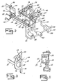
- FIGURE 5 is a cross-section view taken along line 5-5 of Figure 4;
- FIGURE 6 is a cross-section view taken along line 6-6 of Figure 4;
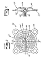
- FIGURE 7 is plan view of a flexure pivot assembly of the preferred embodiment; and
- FIGURE 8 is a cross-section view of the flexure pivot assembly, taken along line 8-8 of Figure 7.
- Referring to Figure 1, the preferred embodiment of the present invention is a
controller 10. For illustration of one possible adaption, thecontroller 10 is shown to be yoke-mounted on the actuator of acontrol valve 12. The vibration resistant design of thecontroller 10 makes it especially suitable for such mounting. The controller may also be mounted on a pipestand, on a wall or in a panel. - As adapted as shown, the
controller 10 controls process pressure in the pipeline (not shown) into which thevalve 12 is positioned. Agauge 14 reports the pressure of a supply line 108 (Figure 2) to thecontroller 10, andgauge 18 reports the pressure of a controller output conduit or line 20 (Figure 2). A process pressure andset point display 22 reports the operator - adjusted set point and the process pressure. Thegauges controller 10, are contained within ahousing 24. As most preferred, thehousing 24 is a plastic suitable to withstand corrosive environments, as found in chemical plants and on offshore oil platforms. Thecontroller 10 finds use in applications throughout the power, chemical, oil and gas industries, wherever accurate process monitoring and control are required. - As will be described in detail, the
controller 10 operates by comparing the process pressure with the operator-adjusted set point, to deliver a pneumatic signal to a control element. This is accomplished so that process pressure changes toward the set point. Thecontroller 10 may be modified for proportional-only control, proportional-plus-reset control, proportional-plus-reset-plus-rate control and differential gap control. - The proportional-plus-reset control modification is shown in Figure 2, with anti-reset windup. Referring to Figures 2 and 4-6, the
controller 10 includes aninput element 26 such as a Bourdon tube (Figure 4) connected by an input-element connecting link 28 to a process indicator such aspointer 30. Thepointer 30 is mounted upon adead shaft 32 secured to a base such as thehousing 24. This mounting provides for pivoting movement of thepointer 30 about theshaft 32, in response to the driving action of thelink 28. - The
pointer 30 cooperates with ascale 34 to report process pressure. Also cooperating with thescale 34 is a set point indicator and actuator such aspointer 36. Thepointer 36 is, like thepointer 30, mounted on the dead shaft. Manual adjustment determines the location of thepointer 36. The manual adjustment determines the set point, i.e., the desired pressure of the process under control. - The
pointer 36 is linked to anozzle 38 by aset point linkage 40. (The nozzle is hidden from view in Figure 4 by acover 42.) Aset point link 44 is connected to thepointer 36 and to aset point lever 46. Thelever 46 includes ayoke 47 pivotably mounted at two spaced pivot points 49, 51 to thehousing 24, for pivoting about a set point and input axis 48. Manual adjustment of theset point pointer 36 pivots thenozzle 38 through the action of thelinkage 40. - The
pointer 30 andinput connecting link 28 are linked to aflapper 50 by aprocess linkage 52. (Thelinkage 52 is also hidden in Figure 4.) Aprocess beam 54 is connected to thepointer 30 andlink 28, and to a first arm orprocess lever 56 of theflapper 50. Theflapper 50 is mounted to thehousing 24 for pivotal movement about the set point and input axis 48, and more specifically, a pivot point 58 (Figure 3) along the axis 48. As will be described, thepointer 30 and theflapper 50 are driven by theinput element 26 through the connectinglink 28 and through thelinkage 52. - The
nozzle 38 andflapper 50 cooperate pneumatically in the usual fashion. Thenozzle 38 has a flapper-cooperative opening 53 which is the outlet of apneumatic line 60 connected by arelay 62 to theoutput line 20. Proximity of thenozzle 38 to theflapper 50 restricts flow through thenozzle 38 and establishes a pressure in theline 60 increased over that of thenozzle 38 without theflapper 50. Variation of the proximity of thenozzle 38 andflapper 50 causes a variation of the back pressure or nozzle pressure in theline 60. Movement of thenozzle 38 toward theflapper 50, and movement of theflapper 50 toward thenozzle 38, increase pressure in theline 60. Movement of thenozzle 38 andflapper 50 away from each other causes a pressure decrease. This pressure variation is the basis of the process control. - For adjustment of the sensitivity or gain or proportional band of the
controller 10, thenozzle 38 is pivotably mounted on theset point lever 46, and a gain indicator and actuator such as aproportional band adjustment 64 is provided. Rotation of theadjustment 64 about again axis 66 causes pivoting of thenozzle 38 about theaxis 66. Thegain axis 66 is perpendicular to the set point and input axis 48. - As best shown in Figure 3, the
flapper 50 is semicircular, and includes a planar nozzlecooperative surface 69 including twoquadrants flapper 50 is pivotable through positions in which thesurface 69 parallels and intersects the axis 48. Thequadrant 68 is a reverse action quadrant, and thequadrant 70 is a direct action quadrant. Gain is determined by the degree of movement of thenozzle 38 from a position of thenozzle 38 parallel to the axis 48 into eitherquadrant nozzle 38 in thedirect action quadrant 70 results in an increase in process pressure causing an increase in controller output pressure. Positioning in thereverse action quadrant 68 results in an increase in process pressure causing a decrease in controller output pressure. - In addition to the
first arm 56, theflapper 50 has a second arm orfeedback lever 72. Thearm 72 extends from thequadrants feedback mechanism 74. Feedback from the controller output is applied to thearm 72 by themechanism 74, and thereby theflapper 50. The feedback causes pivotal movement of theflapper 50 through afeedback axis 76, which intersects thepivot point 58 and is perpendicular to the set point and input axis 48. - The
feedback mechanism 74 includes a proportional bellows 78 and a reset bellows 80. Again, as shown, thecontroller 10 is modified for proportional-plus-reset control. The bellows 78, 80 are respectively connected to therelay 62 through areset valve 82 byfeedback lines reset valve 82 through arelief valve 88 by a relief line 90. For proportional only control, thelines valves - Pivotal movement of the
flapper 50 about thepivot point 58 is provided by aflexure pivot assembly 92, as shown in Figures 6, 7 and 8. Theassembly 92 includes aretainer 94 mounted to thehousing 24. Aball bearing 96 is centrally mounted between theretainer 94 and aflexure subassembly 98, at thepivot point 58. A trifurcatedflexure member 100 of thesubassembly 98 includes an annular arrangement of circumferentially extending and radially interconnectedbyzantine flexure elements 102. Theelements 102 join anouter rim 104 of themember 100 to aflapper support 106. Therim 104 is joined to theretainer 94, and theflapper support 106 is mounted against theball bearing 96. Freedom of movement of theflapper 50 about thepoint 58, with support and retention, are provided by theelements 102 and thebearing 96. - As so constructed, the controller operates as follows. Manual selection of set point and gain are made by adjustment of the
set point pointer 36 and theproportional band adjustment 64. Input from the process is supplied to thecontroller 10 by theinput element 26, and supply pressure is provided to thecontroller 10 through a supply line 110 into therelay 62. The manual adjustment of theset point lever 36 and theadjustment 64 determine an initial location of thenozzle 38. With the nozzle located in thequadrant 70, thecontroller 10 is a direct-acting controller. Thus, as the process pressure increases, thelink 28,pointer 30,linkage 52 andflapper 50 are moved, to the right as seen in Figure 2. Theflapper 50 moves toward thenozzle 38, restricting flow through thenozzle 38 and increasing pressure in theline 60. The output pressure of thecontroller 10 atline 20 is increased. This increase is fed to thebellows lines flapper 50 away from thenozzle 38. The reset bellows 80 responds by expanding and moving theflapper 50 toward thenozzle 38. These actions counter the flapper movement that resulted from the process pressure change. Together, the actions result in a variation of the output pressure. Absent further independent process pressure fluctuations, process pressure will become substantually equal to the set point pressure. - With the
nozzle 38 located in thequadrant 68, thecontroller 10 is a reverse-acting controller. An increase in process pressure causes a decrease in output pressure, with the components of thecontroller 10 responding accordingly. - The preferred embodiment of the invention has now been described in detail. As should be understood, a variety of changes may be made to the preferred embodiment without departing from the subject matter regarding as invention. Therefore, the following claims are appended to particularly point out and distinctly claim the subject matter regarding as invention.
Claims (15)
Applications Claiming Priority (2)
| Application Number | Priority Date | Filing Date | Title |
|---|---|---|---|
| US312930 | 1981-10-19 | ||
| US06/312,930 US4453559A (en) | 1981-10-19 | 1981-10-19 | Pneumatic controller |
Publications (2)
| Publication Number | Publication Date |
|---|---|
| EP0077765A1 true EP0077765A1 (en) | 1983-04-27 |
| EP0077765B1 EP0077765B1 (en) | 1987-09-16 |
Family
ID=23213638
Family Applications (1)
| Application Number | Title | Priority Date | Filing Date |
|---|---|---|---|
| EP82870054A Expired EP0077765B1 (en) | 1981-10-19 | 1982-10-15 | Pneumatic controller |
Country Status (12)
| Country | Link |
|---|---|
| US (1) | US4453559A (en) |
| EP (1) | EP0077765B1 (en) |
| JP (1) | JPS5877901A (en) |
| AU (1) | AU552133B2 (en) |
| CA (1) | CA1190103A (en) |
| DE (1) | DE3277333D1 (en) |
| ES (1) | ES8308100A1 (en) |
| FI (1) | FI73530C (en) |
| IL (1) | IL67015A0 (en) |
| IN (1) | IN156250B (en) |
| MX (1) | MX155821A (en) |
| ZA (1) | ZA827615B (en) |
Families Citing this family (1)
| Publication number | Priority date | Publication date | Assignee | Title |
|---|---|---|---|---|
| US5439021A (en) * | 1992-09-09 | 1995-08-08 | Fisher Controls International, Inc. | Electro-pneumatic converter |
Citations (4)
| Publication number | Priority date | Publication date | Assignee | Title |
|---|---|---|---|---|
| FR834663A (en) * | 1937-08-06 | 1938-11-29 | Method and apparatus for regulating temperature as a function of time or of a predetermined variation curve | |
| FR1071770A (en) * | 1951-09-29 | 1954-09-06 | Fisher Governor Co Ltd | Balanced fluid pressure regulator |
| US3095003A (en) * | 1960-07-15 | 1963-06-25 | Bristol Company | Measuring and control apparatus |
| US3572360A (en) * | 1969-07-25 | 1971-03-23 | Fisher Governor Co | Pneumatic controller |
Family Cites Families (5)
| Publication number | Priority date | Publication date | Assignee | Title |
|---|---|---|---|---|
| US2776670A (en) * | 1951-09-29 | 1957-01-08 | Fisher Governor Co | Pressure fluid operated balanced control system |
| US3047002A (en) * | 1956-12-05 | 1962-07-31 | Taylor Instrument Co | Controller |
| US3354895A (en) * | 1965-12-14 | 1967-11-28 | Fischer & Porter Co | Pneumatic controller |
| US3515162A (en) * | 1968-11-01 | 1970-06-02 | Foxboro Co | Tilt-ring pneumatic control device |
| JPS5210987A (en) * | 1975-07-16 | 1977-01-27 | Fuji Die Kk | Electrodeposition chain saw |
-
1981
- 1981-10-19 US US06/312,930 patent/US4453559A/en not_active Expired - Lifetime
-
1982
- 1982-10-15 DE DE8282870054T patent/DE3277333D1/en not_active Expired
- 1982-10-15 ES ES516530A patent/ES8308100A1/en not_active Expired
- 1982-10-15 EP EP82870054A patent/EP0077765B1/en not_active Expired
- 1982-10-18 ZA ZA827615A patent/ZA827615B/en unknown
- 1982-10-18 FI FI823557A patent/FI73530C/en not_active IP Right Cessation
- 1982-10-18 IN IN1220/CAL/82A patent/IN156250B/en unknown
- 1982-10-18 JP JP57182693A patent/JPS5877901A/en active Granted
- 1982-10-18 AU AU89451/82A patent/AU552133B2/en not_active Ceased
- 1982-10-18 MX MX194815A patent/MX155821A/en unknown
- 1982-10-18 CA CA000413599A patent/CA1190103A/en not_active Expired
- 1982-10-19 IL IL67015A patent/IL67015A0/en unknown
Patent Citations (4)
| Publication number | Priority date | Publication date | Assignee | Title |
|---|---|---|---|---|
| FR834663A (en) * | 1937-08-06 | 1938-11-29 | Method and apparatus for regulating temperature as a function of time or of a predetermined variation curve | |
| FR1071770A (en) * | 1951-09-29 | 1954-09-06 | Fisher Governor Co Ltd | Balanced fluid pressure regulator |
| US3095003A (en) * | 1960-07-15 | 1963-06-25 | Bristol Company | Measuring and control apparatus |
| US3572360A (en) * | 1969-07-25 | 1971-03-23 | Fisher Governor Co | Pneumatic controller |
Also Published As
| Publication number | Publication date |
|---|---|
| DE3277333D1 (en) | 1987-10-22 |
| JPH0351922B2 (en) | 1991-08-08 |
| ZA827615B (en) | 1984-03-28 |
| FI823557L (en) | 1983-04-20 |
| MX155821A (en) | 1988-05-09 |
| AU8945182A (en) | 1983-04-28 |
| IL67015A0 (en) | 1983-02-23 |
| ES516530A0 (en) | 1983-08-01 |
| ES8308100A1 (en) | 1983-08-01 |
| FI73530B (en) | 1987-06-30 |
| AU552133B2 (en) | 1986-05-22 |
| CA1190103A (en) | 1985-07-09 |
| IN156250B (en) | 1985-06-08 |
| FI823557A0 (en) | 1982-10-18 |
| EP0077765B1 (en) | 1987-09-16 |
| FI73530C (en) | 1987-10-09 |
| US4453559A (en) | 1984-06-12 |
| JPS5877901A (en) | 1983-05-11 |
Similar Documents
| Publication | Publication Date | Title |
|---|---|---|
| US6035878A (en) | Diagnostic device and method for pressure regulator | |
| JP3595554B2 (en) | Valve position controller with pressure feedback, dynamic compensation, and diagnostics | |
| CA2668315C (en) | Intelligent pressure regulator | |
| US6827100B1 (en) | Pressure independent control valve | |
| US5518446A (en) | Fume hood exhaust terminal | |
| EP1269280B1 (en) | Pressure independent control valve | |
| US6217506B1 (en) | Method of controlling a fluid | |
| CA1157928A (en) | Current to pressure converter apparatus | |
| US20050039797A1 (en) | Pressure independent control valve | |
| US4453559A (en) | Pneumatic controller | |
| CA1161523A (en) | Air conditioning control system with master and tracking controllers | |
| EP0192335B1 (en) | Air conditioning control system with enhanced operating range | |
| US2805678A (en) | Pneumatic relays | |
| US2543120A (en) | Stabilizer for pneumatic controls | |
| US3411529A (en) | Fluid regulating apparatus | |
| US3572360A (en) | Pneumatic controller | |
| US3208465A (en) | Process controller | |
| US3749109A (en) | Self-contained relay module unit and system utilizing the same | |
| US2324579A (en) | Automatic control apparatus | |
| JPH04220533A (en) | Sensor system | |
| US2880742A (en) | Fluid pressure ratio controller and control system | |
| JP2587392Y2 (en) | Pneumatic instrument | |
| Higham et al. | Pneumatic instrumentation | |
| US4273149A (en) | Blind pressure pilot | |
| RU2193131C1 (en) | Remote control controller |
Legal Events
| Date | Code | Title | Description |
|---|---|---|---|
| PUAI | Public reference made under article 153(3) epc to a published international application that has entered the european phase |
Free format text: ORIGINAL CODE: 0009012 |
|
| AK | Designated contracting states |
Designated state(s): CH DE FR GB IT LI NL SE |
|
| 17P | Request for examination filed |
Effective date: 19830818 |
|
| GRAA | (expected) grant |
Free format text: ORIGINAL CODE: 0009210 |
|
| AK | Designated contracting states |
Kind code of ref document: B1 Designated state(s): CH DE FR GB IT LI NL SE |
|
| ET | Fr: translation filed | ||
| REF | Corresponds to: |
Ref document number: 3277333 Country of ref document: DE Date of ref document: 19871022 |
|
| ITF | It: translation for a ep patent filed |
Owner name: MODIANO & ASSOCIATI S.R.L. |
|
| PLBE | No opposition filed within time limit |
Free format text: ORIGINAL CODE: 0009261 |
|
| STAA | Information on the status of an ep patent application or granted ep patent |
Free format text: STATUS: NO OPPOSITION FILED WITHIN TIME LIMIT |
|
| 26N | No opposition filed | ||
| ITTA | It: last paid annual fee | ||
| EAL | Se: european patent in force in sweden |
Ref document number: 82870054.2 |
|
| PGFP | Annual fee paid to national office [announced via postgrant information from national office to epo] |
Ref country code: SE Payment date: 19961016 Year of fee payment: 15 |
|
| PGFP | Annual fee paid to national office [announced via postgrant information from national office to epo] |
Ref country code: CH Payment date: 19961023 Year of fee payment: 15 |
|
| PGFP | Annual fee paid to national office [announced via postgrant information from national office to epo] |
Ref country code: NL Payment date: 19961029 Year of fee payment: 15 |
|
| PG25 | Lapsed in a contracting state [announced via postgrant information from national office to epo] |
Ref country code: SE Free format text: LAPSE BECAUSE OF NON-PAYMENT OF DUE FEES Effective date: 19971016 |
|
| PG25 | Lapsed in a contracting state [announced via postgrant information from national office to epo] |
Ref country code: LI Free format text: LAPSE BECAUSE OF NON-PAYMENT OF DUE FEES Effective date: 19971031 Ref country code: CH Free format text: LAPSE BECAUSE OF NON-PAYMENT OF DUE FEES Effective date: 19971031 |
|
| PG25 | Lapsed in a contracting state [announced via postgrant information from national office to epo] |
Ref country code: NL Free format text: LAPSE BECAUSE OF NON-PAYMENT OF DUE FEES Effective date: 19980501 |
|
| REG | Reference to a national code |
Ref country code: CH Ref legal event code: PL |
|
| NLV4 | Nl: lapsed or anulled due to non-payment of the annual fee |
Effective date: 19980501 |
|
| EUG | Se: european patent has lapsed |
Ref document number: 82870054.2 |
|
| PGFP | Annual fee paid to national office [announced via postgrant information from national office to epo] |
Ref country code: FR Payment date: 19991011 Year of fee payment: 18 |
|
| PGFP | Annual fee paid to national office [announced via postgrant information from national office to epo] |
Ref country code: GB Payment date: 19991013 Year of fee payment: 18 |
|
| PGFP | Annual fee paid to national office [announced via postgrant information from national office to epo] |
Ref country code: DE Payment date: 19991018 Year of fee payment: 18 |
|
| PG25 | Lapsed in a contracting state [announced via postgrant information from national office to epo] |
Ref country code: GB Free format text: LAPSE BECAUSE OF NON-PAYMENT OF DUE FEES Effective date: 20001015 |
|
| GBPC | Gb: european patent ceased through non-payment of renewal fee |
Effective date: 20001015 |
|
| PG25 | Lapsed in a contracting state [announced via postgrant information from national office to epo] |
Ref country code: FR Free format text: LAPSE BECAUSE OF NON-PAYMENT OF DUE FEES Effective date: 20010629 |
|
| PG25 | Lapsed in a contracting state [announced via postgrant information from national office to epo] |
Ref country code: DE Free format text: LAPSE BECAUSE OF NON-PAYMENT OF DUE FEES Effective date: 20010703 |
|
| REG | Reference to a national code |
Ref country code: FR Ref legal event code: ST |