EP0077764A1 - Capteur de pression à effet piézoélectrique - Google Patents
Capteur de pression à effet piézoélectrique Download PDFInfo
- Publication number
- EP0077764A1 EP0077764A1 EP82870052A EP82870052A EP0077764A1 EP 0077764 A1 EP0077764 A1 EP 0077764A1 EP 82870052 A EP82870052 A EP 82870052A EP 82870052 A EP82870052 A EP 82870052A EP 0077764 A1 EP0077764 A1 EP 0077764A1
- Authority
- EP
- European Patent Office
- Prior art keywords
- chamber
- transducer
- diaphragm
- sensor
- fluctuations
- Prior art date
- Legal status (The legal status is an assumption and is not a legal conclusion. Google has not performed a legal analysis and makes no representation as to the accuracy of the status listed.)
- Withdrawn
Links
Images

Classifications
-
- G—PHYSICS
- G01—MEASURING; TESTING
- G01L—MEASURING FORCE, STRESS, TORQUE, WORK, MECHANICAL POWER, MECHANICAL EFFICIENCY, OR FLUID PRESSURE
- G01L9/00—Measuring steady of quasi-steady pressure of fluid or fluent solid material by electric or magnetic pressure-sensitive elements; Transmitting or indicating the displacement of mechanical pressure-sensitive elements, used to measure the steady or quasi-steady pressure of a fluid or fluent solid material, by electric or magnetic means
- G01L9/0001—Transmitting or indicating the displacement of elastically deformable gauges by electric, electro-mechanical, magnetic or electro-magnetic means
- G01L9/0008—Transmitting or indicating the displacement of elastically deformable gauges by electric, electro-mechanical, magnetic or electro-magnetic means using vibrations
- G01L9/0022—Transmitting or indicating the displacement of elastically deformable gauges by electric, electro-mechanical, magnetic or electro-magnetic means using vibrations of a piezoelectric element
-
- G—PHYSICS
- G01—MEASURING; TESTING
- G01F—MEASURING VOLUME, VOLUME FLOW, MASS FLOW OR LIQUID LEVEL; METERING BY VOLUME
- G01F1/00—Measuring the volume flow or mass flow of fluid or fluent solid material wherein the fluid passes through a meter in a continuous flow
- G01F1/05—Measuring the volume flow or mass flow of fluid or fluent solid material wherein the fluid passes through a meter in a continuous flow by using mechanical effects
- G01F1/20—Measuring the volume flow or mass flow of fluid or fluent solid material wherein the fluid passes through a meter in a continuous flow by using mechanical effects by detection of dynamic effects of the flow
- G01F1/32—Measuring the volume flow or mass flow of fluid or fluent solid material wherein the fluid passes through a meter in a continuous flow by using mechanical effects by detection of dynamic effects of the flow using swirl flowmeters
- G01F1/325—Means for detecting quantities used as proxy variables for swirl
- G01F1/3259—Means for detecting quantities used as proxy variables for swirl for detecting fluid pressure oscillations
Definitions
- This invention relates to a fluid pressure sensor, and more particularly, to a piezoelectric, vortex-shedding flowmeter pressure sensor.
- Vortex frequency can be measured by sensing the frequency of fluid pressure fluctuation at a fixed point in the street, since the pressure at the fixed point fluctuates between a first pressure, when a vortex is present at the point, and a second pressure, when a vortex is absent.
- Piezoelectric material is a desirable material as a pressure sensor.
- the material operates without external power supply, and responds well to applied pressure fluctuation, with an electrical signal which can be amplified for electronic processing.
- piezoelectric material would seem an obvious choice for the sensing of fluid pressure in a von Karman vortex street. Recognition of this desirability was evidenced long ago in U.S. Patents 2,809,520; 3,116,639 and 3,218,852.
- the identified sensor of Curran et al may be advantageous, it involves many parts and the filling of a chamber with oil. (See Figure 7 of Curran et al.) As a result, assembly may be complex. Moreover, the piezoelectric disc employed in the sensor operates in a flexure mode. (Curran et al, column 7, lines 31-35.) I.e., the center of the disc moves laterally relative to the disc edges such that the disc is flexed into varying degrees of curvature. This mode of operation requires relatively wide deflection of the piezoelectric disc for signal generation.
- piezoelectric materials have been long known to be desirable for vortex-shedding flow meter pressure sensors, but the art to date has failed to discover a simplified, rugged piezoelectric sensor suitable for commercial offering. As a result, most commercial offerings of sensors continue to be of the hot wire and other non-piezoelectric types.
- An object of this invention is to provide a piezoelectric pressure sensor which is suitable for sensing dynamic fluid pressure.
- Another object of this invention is to provide a piezoelectric pressure sensor which is suitable for a vortex-shedding flowmeter.
- Another object of the invention is to provide a piezoelectric pressure sensor suitable for a vortex-shedding flowmeter which is also ingeniously simple.
- a fourth object of the invention is to provide an ingeniously simple piezoelectric sensor for a vortex-shedding flowmeter, which is rugged enough to withstand the high frequency vibrations of a von Karman vortex street (e.g., 10-120 Hz for liquid, 100-1200 Hz for gas in a 50mm conduit), without damage from fatigue or rupture, throughout an extended useful life.
- a von Karman vortex street e.g., 10-120 Hz for liquid, 100-1200 Hz for gas in a 50mm conduit
- a fluid pressure sensor comprising a sensor body, a piezoelectric transducer and a vibratory diaphragm.
- the sensor body defines a sensor chamber with a chamber opening and a chamber surface opposite the opening.
- the diaphragm is mounted on the body and seals the opening.
- the transducer is located in the sensor chamber between the diaphragm and the chamber surface.
- the transducer is in contact with the diaphragm and chamber surface.
- the relative rigidities of the chamber surface, diaphragm and transducer are such that pressure fluctuations outside the chamber against the diaphragm cause compression fluctuations in the transducer.
- the transducer responsively generates an electrical signal related to the compression fluctuations, and the pressure fluctuations.
- the invention is a pressure sensor operating in a compression mode, as opposed to a flexure mode.
- the compression mode involves relatively no deflection, as compared to a flexure mode.
- the invention is a sensor in which the diaphragm is in physical contact with the transducer, and the transducer is in physical contact with the chamber surface. The diaphragm is physically supported by the transducer and chamber surface. Pressure on the diaphragm is directly transmitted to the transducer.
- relatively no stress, fatigue and rupture of the diaphragm occurs, as compared with the sensor of Curran et al.
- the direct physical contact of the diaphragm and transducer involves a simplicity which is ingenious, especially as compared to the commercially-offered sensor of Curran et al.
- Components such as the oil fill, oil ports, spacer rings and clamp rings are absent from the inventive sensor, resulting in ease of manufacture and economy.
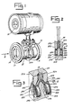
- the first preferred embodiment of the invention is a fluid pressure sensor generally designated 10.
- the sensor 10 is located within and as part of a vortex-shedding flowmeter generally designated 12.
- the purpose of the meter 12 is to measure the velocity of a fluid flowing within a pipe (not shown).
- the meter 12 includes pipe sections 16 and 17 to be fitted to the pipe, and velocity reporting or recording instruments such as electronic signal conditioning and enhancing circuitry associated with a gauge 18.
- the meter 12 operates by creating a von Karman vortex street in the pipe section 16, and measuring the frequency of fluid pressure fluctuations at a fixed point in the street.
- a bluff body 14 is adapted to cause the street within the pipe section 16. Fluid flows past the body 14 in the direction of the arrow 8.
- a sensor-carrying body 20 (also a bluff body) is located downstream of the separation point of the bluff body 14, within the wake thereof, with two (one is shown in Figure I) side surfaces 22a, 22b parallel to and directly inside the rows of the street.
- the vortices of one row pass directly beside one side surface 22a; the vortices of the other row pass directly beside the other side surface 22b.
- the frequency of pressure fluctuations in the street can be measured at the side surfaces 22a, 22b.
- the frequency is measured by the sensor 10, which is located on and within the body 20.
- the sensor includes the portion 24 of the body 20 adjacent the vortex rows, and two vibratory diaphragms 26a, 26b.
- One diaphragm 26a is located on the one side surface 22a, and the other diaphragm 26b is located on the other side surface 22b.
- the sensor further includes two sensor chambers 28a, 28b; two piezoelectric discs 30a, 30b; two pairs 32a, 34a and 32b, 34b of electrical leads; and two electrical insulators 35a, 35b.
- the sensor chambers 28a, 28b extend generally perpendicular to the body side surfaces 22a, 22b.
- the piezoelectric discs 30a, 30b are located within the chambers 28a, 28b and the leads 32a, 32b, 34a, 34b extend from within the chambers through a passage 36 in the body 20 toward the gauge 18.
- the leads are electrically connected to the signal conditioning and enhancing circuitry.
- the pairs of sensor chambers 28a, 28b; discs 30a, 30b; leads 32a, 34a, 32b, 34b; and insulators 35a, 35b are substantially identical to each other.
- the chamber 28a, disc 30a, and leads 32a, 34a are mirror images of the chamber 28b, disc 30b, and leads 32b, 34b, respectively.
- only chamber 28a, disc 30a, leads 32a, 34a and insulator 35a are now described.
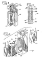
- Chamber 28a is a substantially cylindrical boring, with a counterbore.
- a sidewall 38a of the chamber 28a extends from a substantially circular chamber opening in the body side surface 22a, inward of the body portion 24.
- the sidewall 38a has a substantially uniform diameter, from a ledge 42a adjacent the body side surface 22a to a substantially circular, inner chamber surface 44a.
- the surface 44a meets the sidewall 38a to form the "bottom" of the chamber 28a.
- the surface 44a is substantially planar, substantially circular, and parallels the side surface 22a and ledge 42a.
- the ledge 42a supports the periphery of the diaphragm 26a, which is a thin, circular member.
- the diameters of the sidewall portion 40a and diaphragm 26a are sized to provide a snug fit between the diaphragm 26a and sidewall portion 40a.
- the width of the sidewall portion 40a is sized to provide for support of the diaphragm 26a by the ledge 42a, with the outer surface of the diaphragm 26a being substantially coplanar with the body side surface 22a.
- the diaphragm 26a is secured to the ledge 42a.
- a laser weld may, for example, seal the diaphragm 26a about its periphery to the ledge.
- the seal isolates the interior of the chamber 28a from the fluid in the flowmeter 12, to provide a benign environment for the disc 30a, leads 32a, 34a and insulator 35a.
- the laser weld is especially desirable for the seal, to eliminate disc damage from overheating.
- the disc 30a is fitted within the chamber 28a between the two leads 32a, 34a, and the insulator 35a.
- the disc 30a is in direct physical contact with the leads and insulator, and thereby in indirect physical contact with the diaphragm 26a, the inner chamber surface 44a and the sidewall 38a. More specifically, the disc 30a is sandwiched between a thin, planar and circular portion 46a of the lead 32a and a substantially identical portion 48a of the lead 34a.
- the lead portion 46a is parallel to, and abuts, the diaphragm 26a over its whole surface, while the lead portion 48a is parallel to, and abuts, the chamber inner surface 44a over its whole surface.
- the insulator 35a extends around the edge of the disc 30a along the chamber sidewall 38a, from one side of the narrow strip 50a to the other side thereof.
- the disc 30a, leads 32a, 34a, and insulator -35a are snugly dry- mounted in the chamber 28a, with allowance for disc dimensional changes on the order of several microinches. They are not attached to each other in the chamber 28a, or to the diaphragm 26a or body 20. No fluid is present in the chamber 28a.
- the disc 30a is a piezoelectric transducer, and more specifically, a cylindrical disc of ceramic or crystalline material having piezoelectric properties.
- a cylindrical disc of ceramic or crystalline material having piezoelectric properties is made by the Vernitron Corporation of Bedford, Ohio. Compression across the opposite, planar surfaces of the disc causes the disc to generate positive and negative charges at the opposite surfaces. These charges are related to the amount of compression across the disc.
- the generated charges are carried by the leads 32a, 34a to the gauge 18. Electrical contact with the charged surfaces of the disc 30a is provided by the circular portions 46a, 48a of the leads.
- the leads are formed by copper deposit on a polyimide film, etching to remove undesired deposit, application of a second film, and stamping to separate completed leads.
- the insulator 35a is also formed of an insulation (e.g., polyimide) coated copper or other stiff and springy material.
- the polyimide film completely envelopes the copper.
- the insulator is initially formed as a flat strip, with the copper providing the support and flexibility required for shaping of the insulator 35a.
- the disc 30a is thus held within the chamber 28a, between the diaphragm 26a and chamber surface 44a.
- the rigidities of the chamber surface 44a, disc 30a and diaphragm 26a are related such that pressure fluctuations applied against the diaphragm 26a cause compression fluctuations in the disc 30a. Since the disc 30a responds to compression fluctuations with an electrical signal related to the compression fluctuations, and since the compression fluctuations are related to the pressure fluctuations, the signal of the disc 30a is related to the pressure fluctuations.
- the frequency of pressure fluctuations adjacent the one body side surface 22a can be determined from the frequency of the signal of the disc 30a.
- each disc 30a, 30b generates an electrical signal.
- the signals have the same frequency, since the vortex rows have the same frequency.
- the signals may be electronically processed together or separately, as desired, to record or report the frequency of fluid pressure fluctuations in the street, and thereby the velocity of the fluid.
- One desired processing alternative is the subtraction of signals from the sensor pair to achieve a high signal to noise ratio.
- the second preferred embodiment is a fluid pressure sensor generally designated 60.
- the sensor 60 includes a portion 64 of a body 62, and two vibratory diaphragms 66a, 66b (not shown in Figures 4 and 6, for clarity).
- One diaphragm 66a is located on one side surface 68a of the body 64
- the other diaphragm 66b is located on the opposite side surface 68b of the body 64.
- the sensor 60 further includes a sensor chamber 70; two piezoelectric plates 72a, 72b; two pairs 74a, 76a and 74b, 76b of electrical leads; and an electrical insulator body 78.
- the sensor chamber 70 extends generally perpendicular to the body side surfaces 68a, 68b through the body portion 64. In planes parallel to the body side surfaces 68a, 68b, the sensor chamber 70 is oblate in shape, as are the diaphragms 66a, 66b.
- the insulator 78 occupies the chamber 70.
- the insulator 78 is externally shaped to match the chamber 70.
- a passage 80 in the insulator 78 is aligned with a passage 82 in the body portion 64, and opens into two plate chambers 84a, 84b in the insulator 78.
- the piezoelectric plates 72a, .72b and the leads 74a, 76a, 74b, 76b are located within the chambers 84a; 84b, respectively.
- the leads extend from within the chambers 84a, 84b through the passages 80, 82.
- the senor 60 is similar to the sensor 10.
- the plates 72a, 72b are sandwiched between their respective leads 74a, 76a, 74b, 76b in indirect physical contact with the respective diaphragms 66a, 66b and inner chamber surfaces 86a, 86b.
- the third preferred embodiment is a sensor 100.
- the sensor 100 is substantially identical to the sensor 10. The exception is that the piezoelectric elements 102a, 102b are oblate and the sensor chambers, leads and diaphragms are shaped to match. Physical interrelationships are retained, and function is enhanced, as with sensor 60, by the increased dimension of the piezoelectric elements in a direction transverse to the street.
- the fourth preferred embodiment is a sensor 110 having the enhanced function of the sensors 60, 100 achieved by pairing piezoelectric discs 30a, 30b and the associated structure of the sensor 10 with two further, spaced discs 30a, 30b and structure (30b discs not shown), for a total of four discs.
- the sensor 10 is equivalent to two sensors 10, with the leads of the 30a discs connected and the leads of the 30b discs connected.
- Vortex-shedding flowmeters of various types may include the invention, as may non-vortex-shedding flowmeters.
- a vortex-shedding flowmeter with a single bluff body may include the invention.
- a vortex-shedding flowmeter may include the invention positioned on a wall of the meter.
- the invention may be applied to diverse flow measurement apparatus, such as may be used in ducts, open channels and wherever the sensing of dynamic fluid pressure is desired.
Applications Claiming Priority (2)
| Application Number | Priority Date | Filing Date | Title |
|---|---|---|---|
| US31154281A | 1981-10-15 | 1981-10-15 | |
| US311542 | 1981-10-15 |
Publications (1)
| Publication Number | Publication Date |
|---|---|
| EP0077764A1 true EP0077764A1 (fr) | 1983-04-27 |
Family
ID=23207374
Family Applications (1)
| Application Number | Title | Priority Date | Filing Date |
|---|---|---|---|
| EP82870052A Withdrawn EP0077764A1 (fr) | 1981-10-15 | 1982-10-13 | Capteur de pression à effet piézoélectrique |
Country Status (9)
| Country | Link |
|---|---|
| EP (1) | EP0077764A1 (fr) |
| JP (1) | JPS5876719A (fr) |
| AU (1) | AU553031B2 (fr) |
| CA (1) | CA1183011A (fr) |
| FI (1) | FI823509L (fr) |
| IL (1) | IL66993A (fr) |
| IN (1) | IN157430B (fr) |
| MX (1) | MX152338A (fr) |
| ZA (1) | ZA827526B (fr) |
Cited By (3)
| Publication number | Priority date | Publication date | Assignee | Title |
|---|---|---|---|---|
| WO1995007014A1 (fr) * | 1993-09-01 | 1995-03-09 | Knowles Electronics, Inc. | Recepteur pour un appareil de correction auditive |
| CN100472184C (zh) * | 2002-05-31 | 2009-03-25 | 萨塞克斯大学知识产权有限公司 | 使用一个涡流流速计监视两相流体流 |
| US9341505B2 (en) | 2014-05-09 | 2016-05-17 | Rosemount Inc. | Anomaly fluid detection |
Citations (2)
| Publication number | Priority date | Publication date | Assignee | Title |
|---|---|---|---|---|
| JPS53149360A (en) * | 1977-06-01 | 1978-12-26 | Yokogawa Hokushin Electric Corp | Flow velocity and flow rate measuring apparatus |
| US4165654A (en) * | 1978-04-14 | 1979-08-28 | Hammitt Frederick G | High response rate pressure pulse sensing probe with wide temperature range applicability |
Family Cites Families (2)
| Publication number | Priority date | Publication date | Assignee | Title |
|---|---|---|---|---|
| DE2832142C2 (de) * | 1978-07-21 | 1983-02-10 | Siemens AG, 1000 Berlin und 8000 München | Strömungsmeßeinrichtung nach dem Prinzip der Kármán'schen Wirbelstraße |
| JPS55152422A (en) * | 1979-05-18 | 1980-11-27 | Tokico Ltd | Detector for velocity of flow and flow rate |
-
1982
- 1982-10-13 EP EP82870052A patent/EP0077764A1/fr not_active Withdrawn
- 1982-10-14 AU AU89353/82A patent/AU553031B2/en not_active Ceased
- 1982-10-14 ZA ZA827526A patent/ZA827526B/xx unknown
- 1982-10-14 FI FI823509A patent/FI823509L/fi not_active Application Discontinuation
- 1982-10-14 JP JP57179162A patent/JPS5876719A/ja active Pending
- 1982-10-14 IN IN1199/CAL/82A patent/IN157430B/en unknown
- 1982-10-14 CA CA000413463A patent/CA1183011A/fr not_active Expired
- 1982-10-14 MX MX194787A patent/MX152338A/es unknown
- 1982-10-15 IL IL66993A patent/IL66993A/xx unknown
Patent Citations (2)
| Publication number | Priority date | Publication date | Assignee | Title |
|---|---|---|---|---|
| JPS53149360A (en) * | 1977-06-01 | 1978-12-26 | Yokogawa Hokushin Electric Corp | Flow velocity and flow rate measuring apparatus |
| US4165654A (en) * | 1978-04-14 | 1979-08-28 | Hammitt Frederick G | High response rate pressure pulse sensing probe with wide temperature range applicability |
Non-Patent Citations (3)
| Title |
|---|
| (R.E.GARFORD AND G.J.THOMBLIN) * |
| (S.T.MARKS) * |
| PATENTS ABSTRACTS OF JAPAN, vol. 3, no. 21(E-92), 21st February 1979, page 129E92; & JP - A - 53 149 360 (YOKOGAWA DENKI SEISAKUSHO K.K.) (26-12-1978) * |
Cited By (4)
| Publication number | Priority date | Publication date | Assignee | Title |
|---|---|---|---|---|
| WO1995007014A1 (fr) * | 1993-09-01 | 1995-03-09 | Knowles Electronics, Inc. | Recepteur pour un appareil de correction auditive |
| CN100472184C (zh) * | 2002-05-31 | 2009-03-25 | 萨塞克斯大学知识产权有限公司 | 使用一个涡流流速计监视两相流体流 |
| US7580801B2 (en) | 2002-05-31 | 2009-08-25 | University Of Sussex Intellectual Property Limited | Monitoring of two-phased fluid flow |
| US9341505B2 (en) | 2014-05-09 | 2016-05-17 | Rosemount Inc. | Anomaly fluid detection |
Also Published As
| Publication number | Publication date |
|---|---|
| IL66993A (en) | 1986-08-31 |
| FI823509A0 (fi) | 1982-10-14 |
| AU553031B2 (en) | 1986-07-03 |
| JPS5876719A (ja) | 1983-05-09 |
| ZA827526B (en) | 1983-11-30 |
| CA1183011A (fr) | 1985-02-26 |
| AU8935382A (en) | 1984-04-19 |
| IL66993A0 (en) | 1983-02-23 |
| IN157430B (fr) | 1986-03-29 |
| FI823509L (fi) | 1983-04-16 |
| MX152338A (es) | 1985-06-28 |
Similar Documents
| Publication | Publication Date | Title |
|---|---|---|
| US4559832A (en) | Piezoelectric pressure frequency sensor | |
| US5447073A (en) | Multimeasurement replaceable vortex sensor | |
| US5463904A (en) | Multimeasurement vortex sensor for a vortex-generating plate | |
| US4735098A (en) | Dual diaphragm differential pressure transducer | |
| US4085614A (en) | Vortex flow meter transducer | |
| US4670733A (en) | Differential pressure transducer | |
| JP3133759B2 (ja) | 応力遮断用凹部付き圧力トランスミッタ | |
| US3972232A (en) | Vortex flow meter apparatus | |
| CA1076832A (fr) | Transmetteur de pression differentielle, avec dispositif de protection du capteur | |
| US6352000B1 (en) | Vortex flow sensor | |
| EP0934511B1 (fr) | Unite de mesure de la pression d'un fluide comportant un reseau de mesure a deflexion de diaphragme | |
| GB1577915A (en) | Differential pressure sensor capsule with low acceleration sensitivity | |
| US3479879A (en) | Manometer | |
| US4680971A (en) | Dual diaphragm differential pressure transducer | |
| US4073191A (en) | Differential pressure transducer | |
| US6041659A (en) | Methods and apparatus for sensing differential and gauge static pressure in a fluid flow line | |
| RU2691285C1 (ru) | Преобразователь вихрей вихревого расходомера | |
| US4241325A (en) | Displacement sensing transducer | |
| EP0144937B1 (fr) | Débitmètre à tourbillons | |
| EP0077764A1 (fr) | Capteur de pression à effet piézoélectrique | |
| GB2084324A (en) | Vortex Shedding Fluid Flowmeter | |
| US3235826A (en) | Pressure transducer | |
| US3530719A (en) | Pressure transducers | |
| CA1223452A (fr) | Capteur piezoelectrique de frequence de fluctuation de pression | |
| US5109703A (en) | Vortex flow meter |
Legal Events
| Date | Code | Title | Description |
|---|---|---|---|
| PUAI | Public reference made under article 153(3) epc to a published international application that has entered the european phase |
Free format text: ORIGINAL CODE: 0009012 |
|
| AK | Designated contracting states |
Designated state(s): CH DE FR GB IT LI NL SE |
|
| STAA | Information on the status of an ep patent application or granted ep patent |
Free format text: STATUS: THE APPLICATION IS DEEMED TO BE WITHDRAWN |
|
| 18D | Application deemed to be withdrawn |
Effective date: 19831228 |
|
| RIN1 | Information on inventor provided before grant (corrected) |
Inventor name: LENZ, GARY ALAN Inventor name: WIKLUND, DAVID EUGENE Inventor name: BURLAGE, BRIAN JOSEPH |