EP0077516A1 - Insulators - Google Patents
Insulators Download PDFInfo
- Publication number
- EP0077516A1 EP0077516A1 EP82109397A EP82109397A EP0077516A1 EP 0077516 A1 EP0077516 A1 EP 0077516A1 EP 82109397 A EP82109397 A EP 82109397A EP 82109397 A EP82109397 A EP 82109397A EP 0077516 A1 EP0077516 A1 EP 0077516A1
- Authority
- EP
- European Patent Office
- Prior art keywords
- insulator
- insulation
- rubber
- bands
- belt
- Prior art date
- Legal status (The legal status is an assumption and is not a legal conclusion. Google has not performed a legal analysis and makes no representation as to the accuracy of the status listed.)
- Granted
Links
Images


Classifications
-
- H—ELECTRICITY
- H01—ELECTRIC ELEMENTS
- H01B—CABLES; CONDUCTORS; INSULATORS; SELECTION OF MATERIALS FOR THEIR CONDUCTIVE, INSULATING OR DIELECTRIC PROPERTIES
- H01B17/00—Insulators or insulating bodies characterised by their form
- H01B17/56—Insulating bodies
-
- H—ELECTRICITY
- H01—ELECTRIC ELEMENTS
- H01H—ELECTRIC SWITCHES; RELAYS; SELECTORS; EMERGENCY PROTECTIVE DEVICES
- H01H33/00—High-tension or heavy-current switches with arc-extinguishing or arc-preventing means
- H01H33/60—Switches wherein the means for extinguishing or preventing the arc do not include separate means for obtaining or increasing flow of arc-extinguishing fluid
- H01H33/66—Vacuum switches
- H01H33/662—Housings or protective screens
- H01H33/66207—Specific housing details, e.g. sealing, soldering or brazing
-
- H—ELECTRICITY
- H01—ELECTRIC ELEMENTS
- H01B—CABLES; CONDUCTORS; INSULATORS; SELECTION OF MATERIALS FOR THEIR CONDUCTIVE, INSULATING OR DIELECTRIC PROPERTIES
- H01B17/00—Insulators or insulating bodies characterised by their form
- H01B17/50—Insulators or insulating bodies characterised by their form with surfaces specially treated for preserving insulating properties, e.g. for protection against moisture, dirt, or the like
-
- H—ELECTRICITY
- H01—ELECTRIC ELEMENTS
- H01H—ELECTRIC SWITCHES; RELAYS; SELECTORS; EMERGENCY PROTECTIVE DEVICES
- H01H33/00—High-tension or heavy-current switches with arc-extinguishing or arc-preventing means
- H01H33/60—Switches wherein the means for extinguishing or preventing the arc do not include separate means for obtaining or increasing flow of arc-extinguishing fluid
- H01H33/66—Vacuum switches
- H01H33/662—Housings or protective screens
- H01H33/66207—Specific housing details, e.g. sealing, soldering or brazing
- H01H2033/6623—Details relating to the encasing or the outside layers of the vacuum switch housings
Landscapes
- High-Tension Arc-Extinguishing Switches Without Spraying Means (AREA)
- Insulating Bodies (AREA)
- Insulators (AREA)
- Check Valves (AREA)
Abstract
Description
- This invention relates to insulators, and more particularly, cylindrical insulators, such as insulating members of vacuum circuit-breakers, insulation operating rods, or the like which are disposed in dirty or wet circumstances, each insulator comprising insulation belts or bands to increase insulation ability and creeping distance.
- Recently, it has been required for electric installation to make compact from the viewpoint of installation space and for electric apparatus to design them within design limit of insulation technique. Vacuum circuit-breakers are typical examples for this tendency and have been largely reduced in their shapes and they have been widely used by piling them in multi-stages in a switchboard. Thus, many cases have occurred for using them in adverse circumstances under dirty or wet condition.
- Generally, an insulating vessel of a vacuum circuit-breaker, i.e., a vacuum switch is required to possess high insulation ability and high gas-tight characteristic as well as its compactness. For these requirements, the vacuum switch is generally made of glass or ceramics and has a cylindrical configuration. However, since the insulating vessel of such vacuum switch has an insulation distance of creeping surface less than that of a conventional corrugated insulator, voltage stress on the creeping surface will become high and the insulation characteristics will be degraded in a case where the vacuum switch is disposed in a contaminated or wet condition. Particularly, in a breaking time of a capacitor circuit, an interelectrode voltage is duplicated, so that a flash- over phenomenon may easily occur on the surface of the insulating vessel of the vacuum circuit-breaker to thereby fail in the circuit-breaking.
- At a time of inspection or maintenance of a vacuum switch which is contained in a casing such as that disposed on a pole, voltage at the outside of the casing is inspect- ed by a voltage detector to confirm the condition of contact opening of the switch, and in this case, when insulation condition on the outer surface of the insulating vessel is degraded by dirt, dust, or moisture, the detector may erroneously detect the voltage even if the contact'of the switch is normally opened. In addition, with insulators made of organic materials such as insulation operating rods of switching mechanisms, tracking phenomenon, which finally results in insulation breakdown in an adverse case, may be developed by creeping discharge when the outer surfaces of the insulators of these types are under dirty or wet condition.
- From further point of view, recently there has been provided a vacuum switch the outer surface of which is coated with such insulating film as a resin film,- the thus coated resin may easily be dried and water repellent characteristic of the resin will be degraded as time elapses because of adhered dust or the like.
- It is an object of this invention to provide improved insulators capable of obviating defects encountered in the prior art and attaining high insulation ability even if they are disposed in dirty or wet circumstances.
- Another object of this invention is to provide an improved insulator provided with an insulation band for increasing insulation ability and creeping distance on the outer surface of the insulator.
- According to this invention, there is provided insulators having a cylindrical configuration, each comprising a plurality of insulation bands each provided with water repellent oil-bleed characteristic and disposed on the outer surface of the cylindrical insulator.
- In the accompanying drawings:
- FIG. 1 shows an elevational section of a conventional vacuum switch;
- FIG. 2 shows an elevational section of a vacuum switch to which insulation bands are applied according to this invention;
- FIG. 3 shows a partial sectional view of one modification of the embodiment shown in FIG. 2;
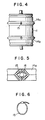
- FIG. 4 shows a schematic view of a vacuum switch provided with modified insulation bands;
- FIG. 5 shows an enlarged view of a portion of the insulation rubber belt shown in FIG. 4;
- FIG. 6 shows a clamp band for clamping the belt shown in FIG. 4; and
- FIGS. 7 and.8 show the other embodiments according to this invention corresponding to those shown in FIGS. 2 and 4, respectively.
- For better understanding of the present invention, a prior art vacuum switch shown in FIG. 1 will first be described, which comprises an outer cylindrical insulating vessel 1, a pair of
separable contacts metal flanges 5 sealing the vessel 1. The construction of the vacuum switch of this type becomes recently compact, and accordingly the outer creeping surface of the insulating vessel 1 has decreased. For this reason, it has been required for the vacuum vessel to have high insulation ability and gas-tight characteristic to prevent lowering of the insulation strength of the outer surface of the vacuum vessel 1. - FIG. 2 shows one embodiment of this invention applied to a conventional vacuum switch shown in FIG. 1 for obviating defects encountered in the prior type device. According to this invention, a plurality of expandable insulation rubber bands (two, in this embodiment) 4a and 4b are secured onto the outer peripheral surface of the insulating vessel l. The insulation rubber band according to this invention is different from a usual rubber and uses a porous rubber, preferably, a silicone rubber in which silicone oil is impregnated between molecules of the silicone rubber layer to thereby impart water repellent and oil-bleeding characteristic to the silicone rubber. To this end the surface of the silicone rubber layer is coated with a thin layer of the silicone oil to cause it to impregnate the silicone rubber layer which is then subjected to heat valcanization. Since the silicone rubber and the silicone oil do not directly react, a matrix other than silicone may be used. The viscosity of the silicone oil affects the matrix used and the spreading speed thereof on the surface of an insulator such as vacuum switch vessel. The silicone oil having a relatively small viscosity can easily be impregnated into the matrix and promptly spreads on the surface of the insulator, but has a relatively short effective life and substantially reverse effects are obtained where a silicone oil having a relatively higher viscosity is used. In our experiments, it was found that the silicone oil having a viscosity of about several thousands to several tens of thousands cst (cm. stokes) is adequate for the present invention.
- One or more insulation rubber bands thus prepared can be fitted around the outer peripheral surface of the vacuum vessel in a direction substantially normal to the axial direction thereof.
- According to the insulation, in the rubber bands applied to the vacuum switch, the silicone oil having strong water repellent characteristic is stored in the silicone rubber bands so that the silicone oil constantly bleeds onto the outer surfaces of the
insulation rubber bands - Glass or ceramic is generally used for a material of the insulating vessel 1 and when these materials are contaminated or wetted, an electroconductive thin film of dirt or wet material readily spreads over the glass or ceramic surface of the vacuum vessel, which results in the lowering of the insulation strength. Since the
insulation rubber bands - FIG. 3 shows one modification of the present invention applied to a vacuum switch, in which the
insulation rubber bands metal flanges 5 sealing the vessel 1 of the vacuum switch, whereby portions of the creeping surfaces of theflanges 5 are effectively utilized as insulating creeping distance. - FIGS. 4 through 6 show another embodiment of this invention, in which
hollow rubber belts clamp bands 15. Thehollow rubber belts 14a and 15b are also made of silicone rubber to which water repellent oil-bleeding characteristic is imparted by the method described above, and one or more belts can be fitted around the outer peripheral surface of the insulating vessel 1 of the vacuum switch to extend in a direction substantially normal to the axial direction thereof. With this embodiment, therubber belts 14a and i 14b are fitted by the steps of cutting the hollow rubber belt so as to have a length slightly longer than the peripheral length of the insulating vessel 1 on which the belt is wound, obliquely cutting both ends of the cut belt, connecting the ends to form a central hole as shown in FIG. 5 which is an enlarged view, and clamping the belt by theclamp band 15 made of, for example, plastic. According to this construction, the silicone oil having a strong water repellent characteristic is stored in the hollow rubber belts and the oil always bleeds out onto the surfaces of the belts and the surface of the insulating vessel near the belts, so that the contact surface of the belt to the insulating vessel is always maintained at a high resistance. - The hollow insulating rubber belt according to this invention can be applied to cylindrical insulators having various shapes or sizes. When fitting the belts, since the belts are fitted by winding them around the insulator without disassembling members connected to the insulator, the belts can readily be fitted at the working field. In addition, the hollow insulation rubber belts are mechanically clamped on the insulating vessel by the clamp band shown in FIG.6, so that the belts can be applied to insulators of circuit-breakers, for example, to which considerably strong striking force is applied.
- In the foregoings, although a hollow rubber belt having triangular cross-section is used for increasing contacting area and creeping distance, the present invention is not limited thereto and a plate-like belt can be used in place of the hollow belt, in which case the plate belt is clamped by a clamp band thereon.
- FIGS. 7a and 7b and FIGS. 8a and 8b schematically show further modifications according to this invention. In FIGS. 7a and 7b, respective
insulation rubber bands insulation rubber belts - It should be noted that the present invention is not limited to the embodiments or modifications described hereinabove such as shapes thereof and can also be applied to any cylindrical organic insulator to prevent the tracking caused by creeping discharge. In addition, regarding an element or device, for example, an arrester, in which inner elements, such as gap elements, a nonlinear resistor, or the like, are contained in an insulating vessel, although discharge characteristics is often remarkably lowered by the disturbance of an electric field stress on the outer surface due to the dirty or wet condition, the electric field can be uniformly stabilized to thereby prevent the lowering of the discharge characteristics by applying a plurality of the insulation rubber bands according to this invention to extend in a direction substantially normal to the axial direction of the arrester.
- According to this invention, as described hereinabove, it is not necessary to manufacture or use insulators having complicated shapes such as corrugated insulators to increase the creeping distance, and insulators having straight outer shapes can easily be manufactured without lowering insulation ability. In addition, the creeping distance and the insulation ability can be easily increased by properly using a plurality of the insulation rubber bands according to the dirty or wet condition in which the insulators are installed. Moreover, problems of tracking, etc., inherent to an insulator made of an organic insulating,material:can be solved.
Claims (7)
Applications Claiming Priority (2)
| Application Number | Priority Date | Filing Date | Title |
|---|---|---|---|
| JP163430/81 | 1981-10-15 | ||
| JP56163430A JPS5866213A (en) | 1981-10-15 | 1981-10-15 | Insulator |
Publications (2)
| Publication Number | Publication Date |
|---|---|
| EP0077516A1 true EP0077516A1 (en) | 1983-04-27 |
| EP0077516B1 EP0077516B1 (en) | 1985-04-10 |
Family
ID=15773742
Family Applications (1)
| Application Number | Title | Priority Date | Filing Date |
|---|---|---|---|
| EP82109397A Expired EP0077516B1 (en) | 1981-10-15 | 1982-10-11 | Insulators |
Country Status (7)
| Country | Link |
|---|---|
| US (1) | US4433203A (en) |
| EP (1) | EP0077516B1 (en) |
| JP (1) | JPS5866213A (en) |
| KR (1) | KR870000349B1 (en) |
| AU (1) | AU534103B2 (en) |
| DE (1) | DE3263015D1 (en) |
| MX (1) | MX151934A (en) |
Cited By (3)
| Publication number | Priority date | Publication date | Assignee | Title |
|---|---|---|---|---|
| EP0187950A1 (en) * | 1984-12-14 | 1986-07-23 | Siemens Aktiengesellschaft | Vacuum switch |
| EP2085980A1 (en) * | 2008-02-04 | 2009-08-05 | Abb Research Ltd. | An electric insulator surface protection element, and an electric insulator provided therewith |
| EP2159811A1 (en) * | 2008-09-01 | 2010-03-03 | ABB Technology AG | High voltage circuit breaker |
Families Citing this family (8)
| Publication number | Priority date | Publication date | Assignee | Title |
|---|---|---|---|---|
| JPS62184728A (en) * | 1986-02-08 | 1987-08-13 | 神鋼電機株式会社 | Vacuum switch |
| JPH0364817A (en) * | 1989-08-01 | 1991-03-20 | Mitsubishi Electric Corp | High voltage vacuum insulation vessel |
| DE4030806A1 (en) * | 1990-09-28 | 1992-04-02 | Siemens Ag | METHOD FOR INCREASING THE VOLTAGE RESISTANCE AND IMPROVING THE CROSS-CURRENT BEHAVIOR OF INSULATION CIRCUITS AND APPLICATION OF THIS METHOD TO VACUUM SWITCHES |
| DE9314617U1 (en) * | 1993-09-23 | 1993-11-11 | Siemens Ag | Vacuum interrupter with improved external dielectric strength |
| JP3386715B2 (en) * | 1997-06-23 | 2003-03-17 | 日本碍子株式会社 | Polymer insulator |
| EP2099038A1 (en) * | 2008-03-04 | 2009-09-09 | ABB Research Ltd | An electric insulator and a method of producing such an electric insulator |
| DE102013202177A1 (en) * | 2013-02-11 | 2014-08-14 | Siemens Aktiengesellschaft | Electrical component |
| JP6161354B2 (en) * | 2013-03-25 | 2017-07-12 | 三菱電機株式会社 | Vacuum valve |
Citations (5)
| Publication number | Priority date | Publication date | Assignee | Title |
|---|---|---|---|---|
| GB1191664A (en) * | 1966-06-07 | 1970-05-13 | Reyrolle & Company Ltd | Improvements relating to Vacuum Switches |
| DE1814498A1 (en) * | 1968-12-13 | 1970-06-25 | Ruhrtal Elek Zitaetsgesellscha | Surface treated insulators |
| US3795646A (en) * | 1970-01-05 | 1974-03-05 | Gen Electric | Cross-linking polyethylene compositions with silicone additive |
| DD119493A1 (en) * | 1975-02-12 | 1976-04-20 | Manfred Jurke | Method and device for improving the insulation of electrical insulators |
| GB2209643A (en) * | 1987-09-04 | 1989-05-17 | Marconi Gec Ltd | Pulse compression radar |
Family Cites Families (7)
| Publication number | Priority date | Publication date | Assignee | Title |
|---|---|---|---|---|
| DE119493C (en) * | ||||
| GB740938A (en) * | 1953-09-09 | 1955-11-23 | Steatite & Porcelain Prod Ltd | Improvements in or relating to high voltage insulators |
| DE1928006B2 (en) * | 1969-06-02 | 1971-05-13 | Baur, Heinz, 3414 Hardegsen | Absorbent plastics |
| JPS5225323B2 (en) * | 1973-05-21 | 1977-07-07 | ||
| JPS5530924Y2 (en) * | 1976-10-08 | 1980-07-23 | ||
| US4393286A (en) * | 1978-08-24 | 1983-07-12 | Tokyo Shibaura Denki Kabushiki Kaisha | Vacuum circuit breakers |
| EP0057098B1 (en) * | 1981-01-26 | 1985-09-04 | Blasius Industries, Inc. | High-voltage insulated connector |
-
1981
- 1981-10-15 JP JP56163430A patent/JPS5866213A/en active Pending
-
1982
- 1982-09-24 US US06/423,292 patent/US4433203A/en not_active Expired - Fee Related
- 1982-09-30 AU AU88893/82A patent/AU534103B2/en not_active Ceased
- 1982-10-07 MX MX194693A patent/MX151934A/en unknown
- 1982-10-11 EP EP82109397A patent/EP0077516B1/en not_active Expired
- 1982-10-11 DE DE8282109397T patent/DE3263015D1/en not_active Expired
- 1982-10-12 KR KR8204579A patent/KR870000349B1/en active
Patent Citations (5)
| Publication number | Priority date | Publication date | Assignee | Title |
|---|---|---|---|---|
| GB1191664A (en) * | 1966-06-07 | 1970-05-13 | Reyrolle & Company Ltd | Improvements relating to Vacuum Switches |
| DE1814498A1 (en) * | 1968-12-13 | 1970-06-25 | Ruhrtal Elek Zitaetsgesellscha | Surface treated insulators |
| US3795646A (en) * | 1970-01-05 | 1974-03-05 | Gen Electric | Cross-linking polyethylene compositions with silicone additive |
| DD119493A1 (en) * | 1975-02-12 | 1976-04-20 | Manfred Jurke | Method and device for improving the insulation of electrical insulators |
| GB2209643A (en) * | 1987-09-04 | 1989-05-17 | Marconi Gec Ltd | Pulse compression radar |
Cited By (4)
| Publication number | Priority date | Publication date | Assignee | Title |
|---|---|---|---|---|
| EP0187950A1 (en) * | 1984-12-14 | 1986-07-23 | Siemens Aktiengesellschaft | Vacuum switch |
| EP2085980A1 (en) * | 2008-02-04 | 2009-08-05 | Abb Research Ltd. | An electric insulator surface protection element, and an electric insulator provided therewith |
| EP2159811A1 (en) * | 2008-09-01 | 2010-03-03 | ABB Technology AG | High voltage circuit breaker |
| CN101667504A (en) * | 2008-09-01 | 2010-03-10 | Abb技术有限公司 | High voltage circuit breaker |
Also Published As
| Publication number | Publication date |
|---|---|
| US4433203A (en) | 1984-02-21 |
| AU534103B2 (en) | 1984-01-05 |
| MX151934A (en) | 1985-05-03 |
| AU8889382A (en) | 1983-05-19 |
| KR870000349B1 (en) | 1987-03-04 |
| DE3263015D1 (en) | 1985-05-15 |
| JPS5866213A (en) | 1983-04-20 |
| EP0077516B1 (en) | 1985-04-10 |
| KR840002150A (en) | 1984-06-11 |
Similar Documents
| Publication | Publication Date | Title |
|---|---|---|
| EP0077516B1 (en) | Insulators | |
| US5291366A (en) | Surge voltage arrester | |
| US4584429A (en) | Electrical assembly including a metal enclosure and a high voltage bushing | |
| CA2612653C (en) | Electric bushing and a method of manufacturing an electric bushing | |
| US4847450A (en) | Stress graded electrical bushing and method of making same | |
| EP2634786A1 (en) | Removable shed sleeve for switch | |
| KR20060048160A (en) | Gas insulated surge arrester | |
| CA1198489A (en) | High voltage resistor for open air insulating arrangements | |
| US4387266A (en) | Foil-insulated high voltage bushing with embossed potential control inserts | |
| US3604830A (en) | Space and temperature accommodating self-cleaning weather casing and high voltage insulating structure employing the same | |
| US5898561A (en) | Capacitor arrangement and method of stabilizing same | |
| EP0911933B1 (en) | Limiting electrical degradation of all-dielectric self supporting cables | |
| US5570264A (en) | Surge arrester | |
| EP1801824A1 (en) | A film, an electrode configuration, a bushing and a method of using an electrode configuration or a bushing | |
| US3812284A (en) | Electrical insulator having additional protective insulating portion | |
| DE19912214A1 (en) | High voltage ceramic capacitor housing | |
| EP1103988A2 (en) | SEmi-capacitance graded bushing insulator of the type with insulating gas filling, such as SF6 | |
| EP0606409B1 (en) | Surge arrester | |
| US5684665A (en) | Modular electrical assembly with conductive strips | |
| CH616265A5 (en) | Compressed-gas-insulated high-voltage bushing | |
| CA1171476A (en) | Adhesive coated electrical apparatus having sublimable protective covering and an assembly method | |
| US4228478A (en) | Overvoltage arrester | |
| US5792996A (en) | Aging resistant, high voltage non-ceramic insulation | |
| CN114175201B (en) | Interrupt unit with vacuum tube and insulating housing | |
| SE9001641D0 (en) | surge |
Legal Events
| Date | Code | Title | Description |
|---|---|---|---|
| PUAI | Public reference made under article 153(3) epc to a published international application that has entered the european phase |
Free format text: ORIGINAL CODE: 0009012 |
|
| AK | Designated contracting states |
Designated state(s): BE DE GB |
|
| 17P | Request for examination filed |
Effective date: 19830310 |
|
| RAP1 | Party data changed (applicant data changed or rights of an application transferred) |
Owner name: KABUSHIKI KAISHA TOSHIBA |
|
| GRAA | (expected) grant |
Free format text: ORIGINAL CODE: 0009210 |
|
| AK | Designated contracting states |
Designated state(s): BE DE GB |
|
| REF | Corresponds to: |
Ref document number: 3263015 Country of ref document: DE Date of ref document: 19850515 |
|
| PLBE | No opposition filed within time limit |
Free format text: ORIGINAL CODE: 0009261 |
|
| STAA | Information on the status of an ep patent application or granted ep patent |
Free format text: STATUS: NO OPPOSITION FILED WITHIN TIME LIMIT |
|
| 26N | No opposition filed | ||
| REG | Reference to a national code |
Ref country code: GB Ref legal event code: 746 |
|
| PGFP | Annual fee paid to national office [announced via postgrant information from national office to epo] |
Ref country code: GB Payment date: 19890930 Year of fee payment: 8 |
|
| PGFP | Annual fee paid to national office [announced via postgrant information from national office to epo] |
Ref country code: BE Payment date: 19891020 Year of fee payment: 8 |
|
| PGFP | Annual fee paid to national office [announced via postgrant information from national office to epo] |
Ref country code: DE Payment date: 19891130 Year of fee payment: 8 |
|
| PG25 | Lapsed in a contracting state [announced via postgrant information from national office to epo] |
Ref country code: GB Effective date: 19901011 |
|
| PG25 | Lapsed in a contracting state [announced via postgrant information from national office to epo] |
Ref country code: BE Effective date: 19901031 |
|
| BERE | Be: lapsed |
Owner name: K.K. TOSHIBA Effective date: 19901031 |
|
| GBPC | Gb: european patent ceased through non-payment of renewal fee | ||
| PG25 | Lapsed in a contracting state [announced via postgrant information from national office to epo] |
Ref country code: DE Effective date: 19910702 |