EP0077080A2 - Method of operating power plants - Google Patents
Method of operating power plants Download PDFInfo
- Publication number
- EP0077080A2 EP0077080A2 EP82109518A EP82109518A EP0077080A2 EP 0077080 A2 EP0077080 A2 EP 0077080A2 EP 82109518 A EP82109518 A EP 82109518A EP 82109518 A EP82109518 A EP 82109518A EP 0077080 A2 EP0077080 A2 EP 0077080A2
- Authority
- EP
- European Patent Office
- Prior art keywords
- plant
- division
- plant state
- cause
- members
- Prior art date
- Legal status (The legal status is an assumption and is not a legal conclusion. Google has not performed a legal analysis and makes no representation as to the accuracy of the status listed.)
- Granted
Links
Images


Classifications
-
- G—PHYSICS
- G21—NUCLEAR PHYSICS; NUCLEAR ENGINEERING
- G21D—NUCLEAR POWER PLANT
- G21D3/00—Control of nuclear power plant
-
- G—PHYSICS
- G05—CONTROLLING; REGULATING
- G05B—CONTROL OR REGULATING SYSTEMS IN GENERAL; FUNCTIONAL ELEMENTS OF SUCH SYSTEMS; MONITORING OR TESTING ARRANGEMENTS FOR SUCH SYSTEMS OR ELEMENTS
- G05B9/00—Safety arrangements
- G05B9/02—Safety arrangements electric
-
- Y—GENERAL TAGGING OF NEW TECHNOLOGICAL DEVELOPMENTS; GENERAL TAGGING OF CROSS-SECTIONAL TECHNOLOGIES SPANNING OVER SEVERAL SECTIONS OF THE IPC; TECHNICAL SUBJECTS COVERED BY FORMER USPC CROSS-REFERENCE ART COLLECTIONS [XRACs] AND DIGESTS
- Y02—TECHNOLOGIES OR APPLICATIONS FOR MITIGATION OR ADAPTATION AGAINST CLIMATE CHANGE
- Y02E—REDUCTION OF GREENHOUSE GAS [GHG] EMISSIONS, RELATED TO ENERGY GENERATION, TRANSMISSION OR DISTRIBUTION
- Y02E30/00—Energy generation of nuclear origin
- Y02E30/30—Nuclear fission reactors
-
- Y—GENERAL TAGGING OF NEW TECHNOLOGICAL DEVELOPMENTS; GENERAL TAGGING OF CROSS-SECTIONAL TECHNOLOGIES SPANNING OVER SEVERAL SECTIONS OF THE IPC; TECHNICAL SUBJECTS COVERED BY FORMER USPC CROSS-REFERENCE ART COLLECTIONS [XRACs] AND DIGESTS
- Y10—TECHNICAL SUBJECTS COVERED BY FORMER USPC
- Y10S—TECHNICAL SUBJECTS COVERED BY FORMER USPC CROSS-REFERENCE ART COLLECTIONS [XRACs] AND DIGESTS
- Y10S706/00—Data processing: artificial intelligence
- Y10S706/902—Application using ai with detail of the ai system
- Y10S706/903—Control
- Y10S706/906—Process plant
- Y10S706/907—Power plant
-
- Y—GENERAL TAGGING OF NEW TECHNOLOGICAL DEVELOPMENTS; GENERAL TAGGING OF CROSS-SECTIONAL TECHNOLOGIES SPANNING OVER SEVERAL SECTIONS OF THE IPC; TECHNICAL SUBJECTS COVERED BY FORMER USPC CROSS-REFERENCE ART COLLECTIONS [XRACs] AND DIGESTS
- Y10—TECHNICAL SUBJECTS COVERED BY FORMER USPC
- Y10S—TECHNICAL SUBJECTS COVERED BY FORMER USPC CROSS-REFERENCE ART COLLECTIONS [XRACs] AND DIGESTS
- Y10S706/00—Data processing: artificial intelligence
- Y10S706/902—Application using ai with detail of the ai system
- Y10S706/911—Nonmedical diagnostics
- Y10S706/914—Process plant
- Y10S706/915—Power plant
Definitions
- This invention relates to a method of operating power plants, and particularly to that by which a pertinent guide for operation can be provided to cope with an abnormity arising on plants.
- CCT Cause-Consequence Tree
- CCT is that of putting the relation of cause and effect of a phenomenon taking place at a plant on the tree and is powerful to function when utilized for a guidance implementation of operation at the time of plant in abnormity.
- a huge quantity of CCT will have to be prepared to multiply the phenomenon with which the operation guide apparatus for a plant utilizing CCT is capable of coping, thus involving a difficulty for implementation and maintenance.
- An object of this invention is to obtain a cause of abnormity arising at a plant with precision.
- Another object of this invention is to obtain an optimal and secure operation necessary to cope with an abnormity arising at a plant.
- Further object of this invention is to minimize capacity of a data base.
- a feature of this invention is to repeat a processing comprising a step to decide an existence of an actual plant state member in a forecasted plant state member and also to estimate a cause of bringing about the state member, when the latter member is not present in the former member, by inputting the forecasted plant state member until all the actual plant state members come to exist in the forecasted plant state member, and a step to forecast all the plant state members to arise after passing a given period of time according to the cause so estimated.
- Fig. 1 is a system diagram of an apparatus for putting a plant operating method into practice which is given in one preferred embodiment of this invention to apply on a boilding water reactor plant;
- Fig. 2 is an explanatory drawing representing an example of the contents of a cause-consequence data base shown in Fig. 1;
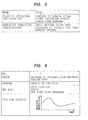
- Fig. 3 is an explanatory drawing representing an example of the contents of a transition forecast data base shown in Fig. 1;
- Fig. 4 is an explanatory drawing representing an example of the contents of an operation data base shown in Fig. 1;
- Fig. 5 is an explanatory drawing representing an example of the contents of a particularization data base shown in Fig. 1;
- Fig. 1 is a system diagram of an apparatus for putting a plant operating method into practice which is given in one preferred embodiment of this invention to apply on a boilding water reactor plant;
- Fig. 2 is an explanatory drawing representing an example of the contents of a cause-consequence data base shown in Fig.
- FIG. 6 is an explanatory drawing representing an example of the contents of a case data base shown in Fig. 1;
- Fig. 7 and Fig. 8 are flowcharts of a processing program shown in Fig. 1;
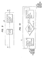
- Fig. 9 is a block diagram of a data conversion division shown in Fig. 7;
- Fig. 10 is a block diagram of a state grasp division shown in Fig. 7;
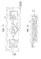
- Fig. 11 is a block diagram of a cause enumeration division shown in Fig. 7;
- Fig. 12 is a block diagram of a forecast division shown in Fig. 7;
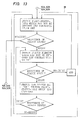
- Fig. 13 is a block diagram of a non-contradiction confirmation division shown in Fig. 7;
- Fig. 14 is a block diagram of a decision division shown in Fig.
- Fig. 15 is a block diagram of an operation enumeration division shown in Fig. 8;
- Fig. 16 is a block diagram of a determination division shown in Fig. 8;
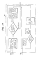
- Fig. 17 is a block diagram of a particularization division shown in Fig. 8;
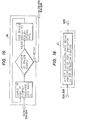
- Fig. 18 is a block diagram of an analogous case retrieval division shown in Fig. 8;
- Fig. 19 is a block diagram of a guidance implementation division shown in Fig. 8;
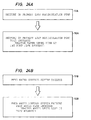
- Fig. 20 is an explanatory drawing of a plant state signal outputted from the data conversion division;
- Fig. 21 is an explanatory drawing of a plant state signal outputted from the state grasp division;
- FIG. 22B are explanatory drawings of a plant state signal outputted from the state grasp division in the cause decision division;
- Fig. 23A and Fig. 23B are explanatory drawings of a plant state signal outputted from the forecast division in the cause decision division;
- Fig. 24A and Fig. 24B are explanatory drawings of a plant state signal outputted from the cause enumeration division and the state grasp division of the cause decision division called recursively;
- Fig. 25 is an explanatory drawing of a plant state signal outputted from the state grasp division of the optimal operation determination division;
- Fig. 27A and Fig. 27B are explanatory drawings of a plant state signal outputted from the forecast division and the state grasp division of the optimal operation determination division called recursively.
- a steam generated at a core 2 in a reactor pressure vessel 1 is sent to a turbine 6 by way of a main steam pipe and then condensed on a.condenser 7 to water.
- the water is supplied into the reactor pressure vessel 1 as.a cooling water by way of a feed-water piping 14.
- the feed-water piping 14 connects a condensate pump 8, a desalter 9, feed-water pumps 10A, lOB, 11A and 11B and a feed-water heater 12 from the upstream side in that order.
- the feed-water pumps 10A, lOB, 11A and 11B are of motor-driven type.
- the feed-water pumps 11A and 11B are driven temporally for start-up and shutdown of a reactor but left standby for backup of the feed-water pumps 10A and 10B during a normal operation of the reactor.
- the feed-water pumps 10A and 10B are driven all the time during operation of the reactor.
- the cooling water coming into the reactor pressure vessel 1 is sent to the core 2 by way of a jet pump 3 by a recirculating pump 4 which is provided on a recirculating system piping 5.
- a water gauge 15 detects a water level (reactor level) 17 in the reactor pressure vessel 1.
- a flow meter 16 detects a discharge flowing in the jet pump 3. The sum of all discharges flowing in the jet pump 3 will indicate a quantity of the cooling water flowing in the core 2.
- the process amount including the reactor level 17 and the jet pump discharge which are measured on various detectors is inputted to a central processor 18B of an electronic computer 18 by way of a process input/output unit 18A of the electronic computer 18.
- the electronic computer 18 has a memory (internal memory and external memory) 18C, besides.
- a consequence processed on the central processor 18B is displayed on a Braun tube (or CRT) 21 provided on a control panel 20.
- the present embodiment comprises obtaining an operation guide for the above reactor plant in abnormity through utilizing a technique of knowledge engineering, carrying out operation at the time of abnormity according to the guidance, thereby coping with an abnormal state of the reactor plant.
- Such operating method will be described as follows.
- the memory 18C of the electronic computer 18 stores a cause-consequence data base 22, a transition forecast data base 23, an operation data base 24, a detail data base 25, a case data base 26 and a processing program 27.
- the cause-consequence data base 22 is that in which the relation of cause and effect is recorded which comprises combining a cause and a consequence to be decided directly from the cause. This is a data storing area which corresponds to that of being called "rule" generally by.people who research knowledge engineering.
- An example of the cause-consequence data base 22 in a boiling water reactor plant is shown in Fig. 2.
- the transition forecast data base 23 is that of storing information to build up a data of the cause-consequence data base 22 as keeping the lapse of time correctly. Stored herein are information on the operating state of each equipment of the plant and the state of each process amount and a technique to obtain, for the process amount for which a value representing the state has been obtained, a time to change the value and a value after a certain time passes.
- An example of the transition forecast data base 23 in a boiling water reactor plant is shown in Fig. 3.
- Fig. 4 represents an example of the operation data base 24 in a boiling water reactor plant.
- the operation data base 24 is that for adding a combination of a condition division and an operation plan with a combination of the state of each process amount and the operating state of each equipment of the plant as the condition division and an operation then conceivable as the operation plan.
- the detail data base 25 is that for recording a detail operating method and operating limit of each equipment of the plant.
- the case data base 26 is that of enclosing a consequence of prior analysis and a record at the time of past operation.
- the detail data base 25 and the case data base 26 in a boiling water reactor plant are shown in Fig. 5 and Fig. 6, respectively.
- the processing program 27 consists of an abnormity decision division 28, a data conversion division 30, a state grasp division 31, a cause decision division 32, an optimal operation determination division 38, a particularization division 42, an analogous case detection division 43 and a guidance implementation division 44.
- the cause decision division 32 has a cause enumeration division 33, a state grasp division 31, a forecast division 34, a non-contradiction confirmation division 35, a recursive call division 36 and a decision division 37 of the cause decision division 32.
- the optimal operation determination division 38 has an operation enumeration division 39, a forecast division 34, a state grasp division 31, a recursive call division 40 and a determination division 41 of the optimal operation determination division 38.
- the data conversion division 30 inputs a plant data which comes in a measured process amount, unifies values of each plant data through a logical decision like majority decision, obtains a member state (an item to indicate one state of the plant) through combining an identifier for the plant data and a consequence transformed into a special value in an apparatus to obtain a guidance for plant operation which indicates a value of the plant data in the processing given below (hereinafter referred to as "operation guide apparatus"), and then outputs these member states in a plant state signal.
- operation guide apparatus A flowchart of the data conversion division 30 is shown in Fig. 9.
- the state grasp division 31 compares each "cause” enclosed in the cause-consequence data base 22 with the inputted plant state signal and selects a "consequence" to come out according to the "cause” corresponding to the plant state signal. Then, the selected consequence is added to the inputted plant state signal as a new member state.
- An epitome of the state grasp division 31 is shown in Fig. 10.
- the cause enumeration division 33 obtains a member state capable of causing each member state of the inputted plant state signal or a combination thereof. through retrieving the "consequence" enclosed in the cause-consequence data base 22, thus outputting a retrieved "consequence”.
- the flowchart is shown in Fig. 11.
- the forecast division 34 inputs the plant state signal and obtains the time until values of each member state of the inputted plant state signal change to those of the next level through executing a calculating technique (program) stored in the transition forecast data base 23. Next, it selects the shortest time of those obtained as above and obtains the value of each member state after passing the shortest time also through executing the calculating technique stored in the transition forecast data base 23. Each member state is then unified and outputted as a plant state signal for the next step.
- An epitome of the forecast division 34 is shown in Fig. 12.
- the non-contradiction confirmation division 35 inputs a reference plant state signal and a single or plural plant state signal for which non-contradiction is confirmed and outputs a plant state signal not included in the original plant state signal and not including a member state taken in by the data conversion division 30.
- Fig. 13 shows a flowchart of the non-contradiction confirmation division 35.
- the decision division 37 inputs a plurality of plant state signals and outputs a plant state signal including each member state most approximate to each member state constituting the plant state signal inputted to the cause decision division 32.
- Fig. 14 shows the contents.
- the operation enumeration division 39 inputs a plant state signal and lists to output operation plans then conceivable by retrieving the condition division of the operation data base 24.
- a flowchart of the operation enumeration division 39 is shown in Fig. 15.
- the determination division 41 inputs a plurality of plant state signals, as shown in Fig. 16, and outputs the plant state signal most approximate to the operation object then prevailing.
- the cause decision division 32 inputs a plant state signal at the time of plant abnormity, actuates the cause enumeration division 33, the state grasp division 31, the forecast division 34, the non-contradiction confirmation division 35, the recursive call division 36 and the decision division 37 to decide a cause of the plant abnormity, and then outputs the plant state signal to which the cause is added.
- the optimal operation determination division 38 inputs the prant state signal outputted from the cause decision division 32, actuates the operation enumeration division 39, the forecast division 34, the state grasp division 31, the recursive call division 40 and the determination division 41 to determine an optimal operating method, and outputs the plant state signal to which a consequence obtained through executing the operation is added.
- the particularization division 42 inputs the plant state signal outputted from the optimal operation determination division 38 and retrieves what signifies an operation of the equipment of the plant according to each member state of the plant state signal. And after ensuring that the retrieved operation satisfies an operation limit of the detail data base 25, it adds a detail operation procedure to the plant state signal. Where the retrieved operation offends against the operation limit of the detail data base 25, it reruns the optimal operation determination division 38.
- a flowchart of the particularization division 42 is shown in Fig. 17.
- the analogous case retrieval division 43 inputs the plant state signal outputted from the particularization division 42, retrieves a cause and a keyword of the case data base 26 and adds that in which the cause coincides or the keyword coincides with a member state of the plant state signal at a constant rate or over to the plant state signal as an analogous case.
- the guidance implementation division 44 inputs the. plant state signal outputted from the analogous case retrieval division 43 and changes the format to output it to CRT 21.
- a plant data representing a process amount of the reactor level 17 and the jet pump discharge is inputted to the central processor 18B by way of the input/output unit 18A.
- the inputted plant data is then subjected to an analog-digital conversion so as to serve well for a processing in the central processor 18B.
- the central processor 18B calls the processing program 27 (Fig. 7 and Fig. 8) which is an operation guide apparatus in the memory 18C and performs a given processing according to the processing program 27.
- the abnormity decision division 28 decides a plant data indicating an abnormal value of those which are inputted.
- a command 29 is outputted and contents of the abnormity are displayed on the control panel 20.
- the processing after the data conversion division 30 of the processing program 27 is executed.
- One or plural plant data 45 measured at the boiling water reactor plant is inputted to the data.conversion division (Fig. 9) 30. Such data as will not satisfy a set point (exceeding or coming lower) are all selected from the plant data 45 and then converted into a plant state signal 46. The data conversion division 30 outputs the plant state signal 46 shown in Fig. 20.
- a plural detector is provided to an important process amount like reactor level. Therefore, it must be ensured that the measured results are coincident with each other. If not, then an erroneous value measured on the detector which is so given through a majority decision is prevented from being inputted to the operation guide apparatus.
- the plant state signal 46 which is an output of the data conversion division 30 is inputted to the state grasp division (Fig. 10) 31.
- the state grasp division 31 supplements information, if any, which is missing with the plant state signal 46 shown in Fig. 20. Namely, the cause division of the cause-consequence data base 22 shown in Fig. 2 is retrieved according to each member state of the inputted plant state signal 46. Next, a decision is made on the retrieved result, and if "YES", the retrieved result is added to the plant state signal 46.
- the cause division of the cause-consequence data base 22 is again retrieved.
- a decision is made on the retrieved result, and if "NO", then a plant state signal 47 to which the above-mentioned retrieved result is added is outputted.
- the plant state signal 47 similar to that of Fig. 20 which is shown in Fig. 21 is outputted.
- input and output of the state grasp division 31 are identical.
- a processing of the cause decision division 32 is executed by inputting the plant state signal 47.
- the consequence division of the cause-consequence data base 22 is again retrieved. However, nothing will be retrieved.
- a decision is made on the retrieved consequence. Since nothing can be retrieved in this case, the cause enumeration division 33 outputs plant state signals 48A and 48B to which "void increasing" and “feed water flow increasing" are added as shown in Fig. 22A and Fig. 22B.
- the state grasp division 31 retrieves items of "void increasing” and “feed water flow increasing” from the cause division of the cause-consequence data base 22 by inputting the plant state signals 48A and 48B and obtains "reactor level ascending" which is an item of the consequence division corresponding thereto. Then, plant state signals 49A and 49B with the above added thereto are outputted.
- the plant state signals 49A and 49B are inputted to the forecast division 34 (Fig. 12).
- a transition of the plant state when the void increases and the feed water flow increases from a combination of "cause” and "consequence" enclosed in the cause-consequence data base 22 can be forecasted by using the forecast division 34.
- the forecast division 34 retrieves a member state in the plant state signals 49A and 49B for which a change time is not calculated and calculates the time in which each retrieved member state changes until there is no member state to be retrieved.
- the time in which the retrieved member state changes refers to a time required for the member state to change from the current level to the next level (the next level being L7 to the current level L6 in the reactor level). Next, whether or not the change time thus obtained is minimum will be decided.
- a change time for "reactor level ascending" to each of "void increasing” and “feed water flow increasing” of the plant state signals 49A and 49B is obtained according to the calculating method (time calculating method) shown in the transition forecast data base 23 of Fig. 3. Then, each member state after the minimum change time thus obtained passes is calculated according to a technique (state calculating method) of the transition forecast data base 23.
- the forecast division 34 outputs plant state signals 50A, 50B with a new plant state signal added which is shown in Fig. 23A and Fig. 23B.
- a change of the phenomenon arising according to "cause” specified by the cause enumeration division 33 (or “consequence” retrieved by the state grasp division 31 of the cause decision division 32), which will be brought as time passes can be obtained by the forecast division 34.
- a decision on whether or not the "cause” estimated by the cause enumeration division 33 is a true cause will thus be facilitated, even if an abnormity occurs with a dynamic process amount of the boiling water reactor plant. In other words, the true cause which brings a plant data indicating the abnormity measured actually at the boiling water reactor can be obtained easily thereby.
- the non-contradiction confirmation division 35 shown in Fig. 13 which has inputted the plant state signals 50A and 50B ensures that the plant state signal produced in consequence does not include a member state which is not present in the plant state actually produced and for which the cause is not estimated by the cause enumeration division 33 itself.
- the confirmed plant state signal is outputted as it is, however, that of having produced a member state which is not present in the actual plant state but taken in by the data conversion division 30 as a consequence is regarded improper as a cause and hence is not outputted.
- the state signals 50A and 50B of Fig. 23A and Fig. 23B are not contradictory and outputted as they are from the non-contradiction confirmation division 35.
- the plant state signals 50A, 50B outputted from the non-contradiction confirmation division 35 are inputted to the recursive call division 36.
- the recursive call division 36 compares the plant state signals 50A and 50B which are outputs of the non-contradiction confirmation division 35 with the plant state signal 47 outputted to the cause decision division 32. Where either one member state of the plant state signals 50A and 50B coincides with the plant state signal 47, the recursive call division 36 will not function. In this case, the plant state signals 50A and 50B are transferred to the decision division 37.
- a member state "jet pump discharge decreasing" is included in the plant state signal 47 but not included in both the plant state signals 50A and 50B.
- the recursive call division 36 therefore calls recursively the cause decision division 32 for which the plant state signals 50A and 50B work as inputs. Namely, the processing from the cause enumeration division 33 to the non-contradiction confirmation division 35 is rerun.
- the plant state signals 50A and 50B are inputted to the cause enumeration division 33.
- the cause enumeration division 33 retrieves the-consequence division of the cause-consequence data base 22 with the member states "void increasing" and “feed water flow increasing" of the plant state signals 50A and 50B as “consequence", thereby obtaining "cause” corresponding thereto.
- Each plant state signal 52A and 52B (Fig. 24A and Fig. 24B) to which these member states are added are outputted from the state grasp division 31 and inputted to the forecast division 34. No change will be brought on the plant state signal from forecasting the transition of the plant state signals 52A and 52B as mentioned by the forecast division 34, and hence they are inputted straight to the non-contradiction confirmation division 35. They are also decided as not contradictory here and outputted straight accordingly.
- the plant state signals 52A and 52B outputted from the non-contradiction confirmation division 35 are inputted to the recursive call division 36.
- the recursive call division 36 compares the plant state signal 47 with the plant state signals 52A and 52B.
- the two member states “reactor level L7" and “jet pump discharge decreasing" of the plant state signal 47 are also present in the plant state signal 52A.
- the recursive call division 36 therefore does not carry out a recursive call of the cause decision division 32 and outputs the plant state signals 52A and 52B to the decision division 37.
- the decision division 37 compares the plant state signals 52A and 52B shown in Fig. 24A and Fig. 24B respectively with the plant state signal 47 of Fig. 21 which indicates an actual plant state of the boiling water reactor plant.
- a feature to decide whether or not a recursive call will have to be carried out through comparing a member state of the first plant state signal inputted to the cause decision division 32 with a member state of the second plant state signal outputted from the non-contradiction confirmation division 35 can be placed on the front stage of the recursive call division 36 separately from the recursive call division 36.
- the member state of the second plant state signal coincides with a part of the member state of the first plant state signal and a new cause is not retrieved at the cause enumeration division 33 after recursive call, it is taken that an abnormal phenomenon due to a different cause has occurred in two or more (multiple phenomenon).
- a cause to produce the member state of the first plant state signal after the member state of the second plant state signal is eliminated from that of the first plant state signal is obtained at the cause decision division 32 similarly as mentioned hereinabove.
- the plant state signal 53 (the plant state signal 52A essentially this time) which is an output of the decision division 37 of the cause decision division 32 is inputted to the operation enumeration division 39 of the optimal operation determination division 38.
- the operation enumeration division 39 retrieves the condition division of the operation data base 24 for each member state of the plant state signal 52A and obtains an operation plan corresponding to the item of the condition division. In this embodiment, the corresponding item is not present in the condition division of_the operation data base 24, as "reactor level L7". Therefore, there is no concrete operation plan in this case, and a plant state signal 54 with the operation. plan "nothing operated" added to the plant state signal 53 is outputted from the operation enumeration division 39.
- the forecast division 34 will function from inputting the plant state signal 54.
- the forecast division 34 outputs a plant state signal 55 to which the change time of each member state of the plant state signal 54 and each member state after the minimum change time passes are added.
- a state changing at the minimum change time is the reactor level
- a member state after passing the minimum time is the "reactor level ascending, L8".
- the plant state signal 55 to which the member state is added is outputted from the forecast division 34.
- the plant state signal 55 is inputted to the state grasp division 31.
- the state grasp division 31 retrieves a consequence “turbine trip” to the member state “reactor level ascending, L8" which is added newly according to the cause-consequence data base 22.
- the state grasp division 31 further retrieves consequences “scram: bus changeover” and “reactor pressure rise” to the cause of retrieved mem- ber state "turbine tip”.
- a plant state signal 56 (Fig. 25) to which these new member states are added is the cut- put of the state grasp division 31.
- the plant state signal 56 is inputted to the recursive call division 40.
- the recursive call divisen 40 has a means to compare the plant state signal inputted to the operation- enumeration division 54 with the plant state signal outputted from the operation enumeration division 54, thereby deciding whether or not a new operation plan is added to the latter signal.
- the recursive call division 40 calls the optimal operation determination division 38 recursively, however, if the decision comes contrary thereto, then the recursive call will not be carried out.
- the operation plan "no operation carried out" is given in this embodiment, therefore a recursive call is made to the optimal operation determination division 38, and a processing is again effected on the operation enumeration division 54, the forecast division 34 and the state grasp division 31, each.
- the plant state signal 56 which is an output of the state grasp division 31 is inputted to the operation enumeration division 39.
- the operation enumeration division 39 inputs the plant state signal 56 and retrieves an operation plan to cope with the member state of this signal.from the operation data base 24.
- an operation "motor driven feed water pump trip" corresponding to "reactor level ascending, L8" is retrieved, and further "no operation carried out” is enumerated as an operation plan..
- Plant state signals to which these operation plans are added i.e. plant state signals 57A and 57B shown in Fig. 26A and Fig. 26B respectively are inputted to the forecast division 34. A transition of the plant state when each operation is carried out is forecasted by the forecast division 34 as mentioned above.
- the state grasp division 31 retrieves a "consequence" corresponding to each member state from the cause-consequence data base 22. Namely, for the plant state signal 58A having an operation plan "motor driven feed water pump trip", a consequence “by-pass valve open” to the cause “reactor pressure high”, a consequence “reactor level drop” to the cause “motor driven feed water pump trip”, a consequence “void descending” to the cause “scram (after a given time passes)” (since the minimum change time passed two times after scram), and a consequence "reactor level descending” to the cause “void decreasing” are retrieved.
- a plant state signal 59A of Fig. 26A to which these retrieved consequences are added is obtained through processing of the state grasp division 31.
- a plant state signal 59B of Fig. 26B to which these retrieved consequences are added is obtained through processing of the state grasp division 31.
- the plant state signals 59A and 59B are inputted t 9 the recursive call division 40.
- the recursive call division 40 determines whether or not the optimal operation determination division 38 will have to be called recursively again according to whether or not the above-mentioned new operation plan has been added in the processing of the operation enumeration division 39 after recursive call. Since "motor driven feed water pump trip" is added as a new operation plan this time, a recursive call of the optimal operation determination division 38 is rerun.
- the plant state signals 59A and 59B are inputted to the operation enumeration division 39. However, the operation enumeration division 39 does not add an operation plan newly to those of plant state signals 59A and 59B.
- the forecast division 34 inputs the plant state signals 59A and 59B outputted from the operation enumeration division 39 to forecast a state of each member state of the plant state signals after the minimum change time passes. Namely, for the plant state signal 59A having an operation plan "motor driven feed water pump trip”, the reactor level is changed to "L2" and the reactor pressure is changed to "descending”. Then, for the plant state signal 59B having an operation plan "no operation carried out”, the reactor level is changed to "L4" and the reactor pressure is changed to "descending”.
- the forecast division 34 outputs plant state signals 60A and 60B shown in Fig. 27A and Fig. 27B for each operation plan.
- the plant state signals 60A and 60B are inputted to the recursive call division 40. Since nothing is added newly at the operation enumeration division 39, a recursive call is not carried out this time. Therefore, the plant state signals 60A and 60B are inputted to the determination division 41.
- the determination division 41 selects either one of the plant state signals 60A and 60B as an optimal operation. Namely, "reactor level L2" will result from carrying out "motor driven feed water pump trip" of the plant state signal 60A, and “reactor level L4" will result from carrying out “no operation carried out”. "No operation carried out” will be most pertinent to "recirculating pump shaft adherent" this time, thereby complying with the operation condition of the boiling water reactor plant, "not to drop reactor level”. Therefore, the plant state signal 60B of Fig. 27B is outputted from the optimal operation determination division.
- the forecast division 34 is provided at the optimal operation determination division 38 in this embodiment, therefore when an operation (retrieved by the operation enumeration division 39) to dissolve the true cause of an abnormal state obtained at the cause decision division 32 is carried out, the future plant state which will be so obtained through carrying out the operation can be forecasted. In other words, the value of a dynamic process amount in the future can be forecasted.
- the recursive call division 40 is also provided at the optimal operation determination division 38, therefore an optimal operation can easily be determined in consideration of the future plant state obtained at the forecast division 34. According to this embodiment, an abnormal state occurring currently at the boiling water reactor plant can be dissolved easily, and an optimal operation high in safety can be selected, too.
- the plant state signal 60B outputted from the determination division 41 of the optimal operation determination division 38 is inputted to the particularization division 42.
- the optimal operation being "no operation carried out"
- the particularization division 42 does not function.
- the particularization division 42 outputs the plant state signal 60B as an output (a plant state signal 61) of the particularization division 42.
- a plant state signal 61 For example, in case "motor driven feed water pump trip" of the plant state signal 60A is carried out and thus a high pressure injection system is operated by "reactor level L2" of the plant state signal 60A, a detail operating method (Fig. 5) of the high pressure injection system is picked out of the detail data base 25, and a plant state signal to which the above is added is outputted from the particularization division 42.
- the analogous case retrieval division 43 shown in Fig. 18 is actuated from inputting the plant state signal 61.
- the analogous case retrieval division 43 retrieves a case analogous to the plant state signal 61 from the case data base 26 which encloses practical cases as shown in Fig. 6.
- Case 1 representing "recirculating pump shaft adherent" shown in Fig. 6 is retrieved, and the contents are added to the plant state signal 61 to develop to a plant state signal 62, which is outputted from the analogous case retrieval division 43.
- the plant state signal 62 is inputted to the guidance implementation division 44 shown in Fig. 19.
- the guidance implementation division 44 outputs the plant state signal 60B shown in Fig. 27B through converting it into a CRT display output (into a character code for CRT, for example). In this case, the detail operating method and the contents of the analogous case are converted likewise.
- the guidance implementation division 44 outputs that for CRT display which indicates the member state representing a cause and also the member state representing contents of the operation to cope therewith. For example, words (cause) and (operation contents) are added after the corresponding member states as: "recirculating pump shaft adherent (cause)" and "no operation carried out (operation contents)".
- An output (plant state signal 60B) of the guidance implementation division 44 is transferred to CRT 21 to display thereon. Observing the operation contents displayed on CRT 21, an operator of the boiling water reactor plant will operate an object equipment of the boiling water reactor plant on a control panel accordingly.
- the operation contents of this embodiment being "no operation carried out", a concrete operation will not be made for the boiling water reactor plant.
- an operation "no operation carried out” is performed for the boiling water reactor plant. From carrying out such operation, a void decreases, the reactor level 17 descends to the level L4, the by-pass valve opens automatically, and thus the reactor pressure drops to a safe state in the boiling water reactor plant.
- contents of the plant state signal 60A are determined to be an optimal operation at the determination division 41, the operator will operate the control panel 20 so as to trip a motor driven feed water pump according to the operation contents displayed on CRT 21..
- the command is given to feed water pumps 10A and 10B in operation from the control panel 20.
- the feed water pumps 10A and 10B come to shutdown.
- phenomena arising on the plant are all displayed on CRT when an actual operation is carried out based on the displayed operation contents, therefore a progress of the operation can be supervised by confirming the change of an actual state of the plant.
- a use of the forecast division 34 may ensure a safe operation of the boiling water reactor plant (safety being ensured even from the motor driven feed water pump in trip) against an abnormal phenomenon which is not conceivable actually like "recirculating pump shaft adherent", thus obtaining an optimal operation high in safety.
- operators are kept from troubles to improve the guidance operation, carry out such erroneous operation as will reduce an effect of the guidance operation, or take much time to cope with a load fluctuation when the plant is activated.
- a guidance coping at all times with a renewed situation can be provided to operators by rerunning the above processing through a generation of a new alarm, another request by the operator, or an interruption of . an internal clock of the operation guide apparatus.
- the plant data can be inputted at every member states at the point in time when the state grasp division 31 is actuated, and the cause division of the cause-consequence data base 22 and the plant state signal are compared with each other.
- causes which are not contradictory each other will be outputted as a plural cause instead of concluding the cause to one only, and the ensuing processing can be done for each of them.
- the operation will not be determined to one only, those which meet the object of operation will be outputted accordingly, and the operator may have an option to select suitably from among them. Then, the processing can be cut to outputting at the point in time when those of meeting the object of operation are found more than the number set initially instead of obtaining an optimal operation.
- the same one as the cause-consequence data base 22 will be used for the operation data base 24, which can be identified by marking up properly for the contents.
- the particularization division 42 and the analogous case retrieval division 43 may be actuated upon indication of the operator. Then, a retrieval of analogous cases may be processed antecedently, or both may be processed concurrently, or either one only may be processed.
- the forecast division 34 can interpret an expression on the transition forecast data base 23 directly to execution, or it can operate for calculation by calling a subroutine for which information is stored on the transition forecast data base 23. Then, a table search can be done directly by the forecast feature or by a private subroutine with a similar technique.
- a similar processing can be implemented on a software by means of a stack instead of using a recursive call feature, or a function to realize the cause decision division 32 and the optimal operation determination division 38 is built on a hardware, which will be connected in series therefor by the number taken enough.
- a large-scale data base is not required., which may facilitate implementation and maintenance. Then, since contents of the data base are independent at every units of configuration as shown in Fig. 2 to Fig. 6, in an extreme case, if any, where a phenomenon which is not included in the data base is produced, a trained operator will cope with such phenomenon by inputting the feature only to the data base, and thus a function of the operation guide apparatus can be amplified.
- This invention can be applied to a pressurized water reactor plant, a fast breeder reactor plant and a thermal power plant, too.
- a true cause of an abnormal state of the plant can be grasped easily.
Abstract
Description
- This invention relates to a method of operating power plants, and particularly to that by which a pertinent guide for operation can be provided to cope with an abnormity arising on plants.
- A method to utilize Cause-Consequence Tree (hereinafter referred to as "CCT") has been proposed hitherto for providing a guide for operation at the time of plant in abnormity.
- CCT is that of putting the relation of cause and effect of a phenomenon taking place at a plant on the tree and is powerful to function when utilized for a guidance implementation of operation at the time of plant in abnormity. However, a huge quantity of CCT will have to be prepared to multiply the phenomenon with which the operation guide apparatus for a plant utilizing CCT is capable of coping, thus involving a difficulty for implementation and maintenance.
- Then, a technique on knowledge engineering which is utilized for medical consultation system will be taken up as the technique for implementation of a guidance system utilizing a small-scale data base effectively.
- An object of this invention is to obtain a cause of abnormity arising at a plant with precision.
- Another object of this invention is to obtain an optimal and secure operation necessary to cope with an abnormity arising at a plant.
- Further object of this invention is to minimize capacity of a data base.
- A feature of this invention is to repeat a processing comprising a step to decide an existence of an actual plant state member in a forecasted plant state member and also to estimate a cause of bringing about the state member, when the latter member is not present in the former member, by inputting the forecasted plant state member until all the actual plant state members come to exist in the forecasted plant state member, and a step to forecast all the plant state members to arise after passing a given period of time according to the cause so estimated.
- Fig. 1 is a system diagram of an apparatus for putting a plant operating method into practice which is given in one preferred embodiment of this invention to apply on a boilding water reactor plant; Fig. 2 is an explanatory drawing representing an example of the contents of a cause-consequence data base shown in Fig. 1; Fig. 3 is an explanatory drawing representing an example of the contents of a transition forecast data base shown in Fig. 1; Fig. 4 is an explanatory drawing representing an example of the contents of an operation data base shown in Fig. 1; Fig. 5 is an explanatory drawing representing an example of the contents of a particularization data base shown in Fig. 1; Fig. 6 is an explanatory drawing representing an example of the contents of a case data base shown in Fig. 1; Fig. 7 and Fig. 8 are flowcharts of a processing program shown in Fig. 1; Fig. 9 is a block diagram of a data conversion division shown in Fig. 7; Fig. 10 is a block diagram of a state grasp division shown in Fig. 7; Fig. 11 is a block diagram of a cause enumeration division shown in Fig. 7; Fig. 12 is a block diagram of a forecast division shown in Fig. 7; Fig. 13 is a block diagram of a non-contradiction confirmation division shown in Fig. 7; Fig. 14 is a block diagram of a decision division shown in Fig. 7; Fig. 15 is a block diagram of an operation enumeration division shown in Fig. 8; Fig. 16 is a block diagram of a determination division shown in Fig. 8; Fig. 17 is a block diagram of a particularization division shown in Fig. 8; Fig. 18 is a block diagram of an analogous case retrieval division shown in Fig. 8; Fig. 19 is a block diagram of a guidance implementation division shown in Fig. 8; Fig. 20 is an explanatory drawing of a plant state signal outputted from the data conversion division; Fig. 21 is an explanatory drawing of a plant state signal outputted from the state grasp division; Fig. 22A and Fig. 22B are explanatory drawings of a plant state signal outputted from the state grasp division in the cause decision division; Fig. 23A and Fig. 23B are explanatory drawings of a plant state signal outputted from the forecast division in the cause decision division; Fig. 24A and Fig. 24B are explanatory drawings of a plant state signal outputted from the cause enumeration division and the state grasp division of the cause decision division called recursively; Fig. 25 is an explanatory drawing of a plant state signal outputted from the state grasp division of the optimal operation determination division; Fig. 26A and Fig. 26B, Fig. 27A and Fig. 27B are explanatory drawings of a plant state signal outputted from the forecast division and the state grasp division of the optimal operation determination division called recursively.
- A plant operating method which is given in one preferred embodiment of this invention to apply on a boiling water reactor plant will now be described with reference to Fig. 1.
- A steam generated at a
core 2 in areactor pressure vessel 1 is sent to aturbine 6 by way of a main steam pipe and then condensed on a.condenser 7 to water. The water is supplied into thereactor pressure vessel 1 as.a cooling water by way of a feed-water piping 14. The feed-water piping 14 connects a condensate pump 8, a desalter 9, feed-water pumps 10A, lOB, 11A and 11B and a feed-water heater 12 from the upstream side in that order. The feed-water pumps 10A, lOB, 11A and 11B are of motor-driven type. The feed-water pumps water pumps water pumps reactor pressure vessel 1 is sent to thecore 2 by way of ajet pump 3 by a recirculating pump 4 which is provided on a recirculatingsystem piping 5. - A
water gauge 15 detects a water level (reactor level) 17 in thereactor pressure vessel 1. Aflow meter 16 detects a discharge flowing in thejet pump 3. The sum of all discharges flowing in thejet pump 3 will indicate a quantity of the cooling water flowing in thecore 2. The process amount including thereactor level 17 and the jet pump discharge which are measured on various detectors is inputted to acentral processor 18B of anelectronic computer 18 by way of a process input/output unit 18A of theelectronic computer 18. Theelectronic computer 18 has a memory (internal memory and external memory) 18C, besides. A consequence processed on thecentral processor 18B is displayed on a Braun tube (or CRT) 21 provided on acontrol panel 20. - The present embodiment comprises obtaining an operation guide for the above reactor plant in abnormity through utilizing a technique of knowledge engineering, carrying out operation at the time of abnormity according to the guidance, thereby coping with an abnormal state of the reactor plant. Such operating method will be described as follows. The
memory 18C of theelectronic computer 18 stores a cause-consequence data base 22, a transitionforecast data base 23, anoperation data base 24, adetail data base 25, acase data base 26 and aprocessing program 27. - The cause-
consequence data base 22 is that in which the relation of cause and effect is recorded which comprises combining a cause and a consequence to be decided directly from the cause. This is a data storing area which corresponds to that of being called "rule" generally by.people who research knowledge engineering. An example of the cause-consequence data base 22 in a boiling water reactor plant is shown in Fig. 2. - The transition
forecast data base 23 is that of storing information to build up a data of the cause-consequence data base 22 as keeping the lapse of time correctly. Stored herein are information on the operating state of each equipment of the plant and the state of each process amount and a technique to obtain, for the process amount for which a value representing the state has been obtained, a time to change the value and a value after a certain time passes. An example of the transitionforecast data base 23 in a boiling water reactor plant is shown in Fig. 3. - Fig. 4 represents an example of the
operation data base 24 in a boiling water reactor plant. Theoperation data base 24 is that for adding a combination of a condition division and an operation plan with a combination of the state of each process amount and the operating state of each equipment of the plant as the condition division and an operation then conceivable as the operation plan. - The
detail data base 25 is that for recording a detail operating method and operating limit of each equipment of the plant. - The
case data base 26 is that of enclosing a consequence of prior analysis and a record at the time of past operation. - The
detail data base 25 and thecase data base 26 in a boiling water reactor plant are shown in Fig. 5 and Fig. 6, respectively. - An epitome of the
processing program 27 will be described with reference to Fig. 7 and Fig. 8. Theprocessing program 27 consists of anabnormity decision division 28, adata conversion division 30, astate grasp division 31, acause decision division 32, an optimaloperation determination division 38, aparticularization division 42, an analogouscase detection division 43 and aguidance implementation division 44. Thecause decision division 32 has acause enumeration division 33, astate grasp division 31, a forecastdivision 34, anon-contradiction confirmation division 35, arecursive call division 36 and adecision division 37 of thecause decision division 32. Further, the optimaloperation determination division 38 has anoperation enumeration division 39, aforecast division 34, astate grasp division 31, arecursive call division 40 and adetermination division 41 of the optimaloperation determination division 38. - The
data conversion division 30 inputs a plant data which comes in a measured process amount, unifies values of each plant data through a logical decision like majority decision, obtains a member state (an item to indicate one state of the plant) through combining an identifier for the plant data and a consequence transformed into a special value in an apparatus to obtain a guidance for plant operation which indicates a value of the plant data in the processing given below (hereinafter referred to as "operation guide apparatus"), and then outputs these member states in a plant state signal. A flowchart of thedata conversion division 30 is shown in Fig. 9. - The
state grasp division 31 compares each "cause" enclosed in the cause-consequence data base 22 with the inputted plant state signal and selects a "consequence" to come out according to the "cause" corresponding to the plant state signal. Then, the selected consequence is added to the inputted plant state signal as a new member state. An epitome of thestate grasp division 31 is shown in Fig. 10. - The
cause enumeration division 33 obtains a member state capable of causing each member state of the inputted plant state signal or a combination thereof. through retrieving the "consequence" enclosed in the cause-consequence data base 22, thus outputting a retrieved "consequence". The flowchart is shown in Fig. 11. - The
forecast division 34 inputs the plant state signal and obtains the time until values of each member state of the inputted plant state signal change to those of the next level through executing a calculating technique (program) stored in the transitionforecast data base 23. Next, it selects the shortest time of those obtained as above and obtains the value of each member state after passing the shortest time also through executing the calculating technique stored in the transitionforecast data base 23. Each member state is then unified and outputted as a plant state signal for the next step. An epitome of theforecast division 34 is shown in Fig. 12. - The
non-contradiction confirmation division 35 inputs a reference plant state signal and a single or plural plant state signal for which non-contradiction is confirmed and outputs a plant state signal not included in the original plant state signal and not including a member state taken in by thedata conversion division 30. Fig. 13 shows a flowchart of thenon-contradiction confirmation division 35. - The
decision division 37 inputs a plurality of plant state signals and outputs a plant state signal including each member state most approximate to each member state constituting the plant state signal inputted to thecause decision division 32. Fig. 14 shows the contents. - The
operation enumeration division 39 inputs a plant state signal and lists to output operation plans then conceivable by retrieving the condition division of theoperation data base 24. A flowchart of theoperation enumeration division 39 is shown in Fig. 15. - The
determination division 41 inputs a plurality of plant state signals, as shown in Fig. 16, and outputs the plant state signal most approximate to the operation object then prevailing. - The
cause decision division 32 inputs a plant state signal at the time of plant abnormity, actuates thecause enumeration division 33, thestate grasp division 31, theforecast division 34, thenon-contradiction confirmation division 35, therecursive call division 36 and thedecision division 37 to decide a cause of the plant abnormity, and then outputs the plant state signal to which the cause is added. - The optimal
operation determination division 38 inputs the prant state signal outputted from thecause decision division 32, actuates theoperation enumeration division 39, theforecast division 34, thestate grasp division 31, therecursive call division 40 and thedetermination division 41 to determine an optimal operating method, and outputs the plant state signal to which a consequence obtained through executing the operation is added. - The
particularization division 42 inputs the plant state signal outputted from the optimaloperation determination division 38 and retrieves what signifies an operation of the equipment of the plant according to each member state of the plant state signal. And after ensuring that the retrieved operation satisfies an operation limit of thedetail data base 25, it adds a detail operation procedure to the plant state signal. Where the retrieved operation offends against the operation limit of thedetail data base 25, it reruns the optimaloperation determination division 38. A flowchart of theparticularization division 42 is shown in Fig. 17. - The analogous
case retrieval division 43 inputs the plant state signal outputted from theparticularization division 42, retrieves a cause and a keyword of thecase data base 26 and adds that in which the cause coincides or the keyword coincides with a member state of the plant state signal at a constant rate or over to the plant state signal as an analogous case. - The
guidance implementation division 44 inputs the. plant state signal outputted from the analogouscase retrieval division 43 and changes the format to output it to CRT 21. - An operating method of a boiling water reactor plant on an apparatus having the above-mentioned features will be described as follows.
- While such a phenomenon will not be conceivable actually, the phenomenon wherein a shaft of the recirculating pump 4 to feed a cooling water to the
core 2 happens to adhere during operation of the boiling water reactor plant is premised for description. When the shaft is adherent as mentioned, the quantity of a cooling water flowing in thecore 2 decreases and a void in thecore 2 increases. The increase in void may lead to an ascent of thereactor level 17. Actually, a phenomenon of the shaft adherence and the void increase is not apparent but a process amount of the measured reactor level and the jet pump discharge is only known. Thereactor level 17 normally comes at a level L4. When thereactor level 17 reaches a level L8, the reactor is shut down urgently (scram). When thereactor level 17 reaches a level L7 immediately before the sram, an indication is given to that effect on thecontrol panel 20. An operator is thus acquainted with an ascent of the reactor level. A plant data representing a process amount of thereactor level 17 and the jet pump discharge is inputted to thecentral processor 18B by way of the input/output unit 18A. The inputted plant data is then subjected to an analog-digital conversion so as to serve well for a processing in thecentral processor 18B. Upon inputting the plant data, thecentral processor 18B calls the processing program 27 (Fig. 7 and Fig. 8) which is an operation guide apparatus in thememory 18C and performs a given processing according to theprocessing program 27. Theabnormity decision division 28 decides a plant data indicating an abnormal value of those which are inputted. When the plant data indicating an abnormal value (thereactor level 17 reaching L7 level in the case of this embodiment) is present, acommand 29 is outputted and contents of the abnormity are displayed on thecontrol panel 20. When there is present further such plant data indicating an abnormal value, the processing after thedata conversion division 30 of theprocessing program 27 is executed. - One or
plural plant data 45 measured at the boiling water reactor plant is inputted to the data.conversion division (Fig. 9) 30. Such data as will not satisfy a set point (exceeding or coming lower) are all selected from theplant data 45 and then converted into aplant state signal 46. Thedata conversion division 30 outputs theplant state signal 46 shown in Fig. 20. - In the boiling water reactor plant, a plural detector is provided to an important process amount like reactor level. Therefore, it must be ensured that the measured results are coincident with each other. If not, then an erroneous value measured on the detector which is so given through a majority decision is prevented from being inputted to the operation guide apparatus.
- In Fig. 21, contents are given in ordinary characters, however, EBCDIC character code or integral number can be used practically.
- The
plant state signal 46 which is an output of thedata conversion division 30 is inputted to the state grasp division (Fig. 10) 31. Thestate grasp division 31 supplements information, if any, which is missing with theplant state signal 46 shown in Fig. 20. Namely, the cause division of the cause-consequence data base 22 shown in Fig. 2 is retrieved according to each member state of the inputtedplant state signal 46. Next, a decision is made on the retrieved result, and if "YES", the retrieved result is added to theplant state signal 46. After that, the cause division of the cause-consequence data base 22 is again retrieved..A decision is made on the retrieved result, and if "NO", then aplant state signal 47 to which the above-mentioned retrieved result is added is outputted. There is nothing to add in this embodiment, and theplant state signal 47 similar to that of Fig. 20 which is shown in Fig. 21 is outputted. In the embodiment, input and output of thestate grasp division 31 are identical. - Since the time of abnormity is premised for operation of the embodiment, a processing of the
cause decision division 32 is executed by inputting theplant state signal 47. - The
plant state signal 47 is inputted first to thecause enumeration division 33 in thecause decision division 32. With each member state of theplant state signal 47 as a "consequence", thecause enumeration division 33 retrieves the member state of theplant state signal 47 from a consequence division of the cause-consequence data base 22 (Fig. 2) and adds an item of the cause division coping with the member state to theplant state signal 47. Namely, the member state of theplant state signal 47 indicates "reactor level = L7" and "jet pump discharge decreasing". Where the member state is present in two or more, the member state higher in importance is subjected to retrieval. An importance of the member state is specified beforehand. In this embodiment, "reactor level = L7" is more important and hence is subjected to retrieval. "Reactor level = L7" is so given as a consequence of the reactor level having ascended, therefore "reactor level ascending" is retrieved from the consequence division of the cause-consequence data base 22, and "void increasing" and "feed water flow increasing" which are items of the cause division corresponding thereto are added to theplant state signal 47. The consequence division of the cause-consequence data base 22 is again retrieved. However, nothing will be retrieved. Next, a decision is made on the retrieved consequence. Since nothing can be retrieved in this case, thecause enumeration division 33 outputs plant state signals 48A and 48B to which "void increasing" and "feed water flow increasing" are added as shown in Fig. 22A and Fig. 22B. - The
state grasp division 31 retrieves items of "void increasing" and "feed water flow increasing" from the cause division of the cause-consequence data base 22 by inputting the plant state signals 48A and 48B and obtains "reactor level ascending" which is an item of the consequence division corresponding thereto. Then, plant state signals 49A and 49B with the above added thereto are outputted. - The plant state signals 49A and 49B are inputted to the forecast division 34 (Fig. 12).
- A transition of the plant state when the void increases and the feed water flow increases from a combination of "cause" and "consequence" enclosed in the cause-
consequence data base 22 can be forecasted by using theforecast division 34. Theforecast division 34 retrieves a member state in the plant state signals 49A and 49B for which a change time is not calculated and calculates the time in which each retrieved member state changes until there is no member state to be retrieved. The time in which the retrieved member state changes refers to a time required for the member state to change from the current level to the next level (the next level being L7 to the current level L6 in the reactor level). Next, whether or not the change time thus obtained is minimum will be decided. A change time for "reactor level ascending" to each of "void increasing" and "feed water flow increasing" of the plant state signals 49A and 49B is obtained according to the calculating method (time calculating method) shown in the transitionforecast data base 23 of Fig. 3. Then, each member state after the minimum change time thus obtained passes is calculated according to a technique (state calculating method) of the transitionforecast data base 23. Theforecast division 34 outputs plant state signals 50A, 50B with a new plant state signal added which is shown in Fig. 23A and Fig. 23B. A change of the phenomenon arising according to "cause" specified by the cause enumeration division 33 (or "consequence" retrieved by thestate grasp division 31 of the cause decision division 32), which will be brought as time passes can be obtained by theforecast division 34. A decision on whether or not the "cause" estimated by thecause enumeration division 33 is a true cause will thus be facilitated, even if an abnormity occurs with a dynamic process amount of the boiling water reactor plant. In other words, the true cause which brings a plant data indicating the abnormity measured actually at the boiling water reactor can be obtained easily thereby. - The
non-contradiction confirmation division 35 shown in Fig. 13 which has inputted the plant state signals 50A and 50B ensures that the plant state signal produced in consequence does not include a member state which is not present in the plant state actually produced and for which the cause is not estimated by thecause enumeration division 33 itself. The confirmed plant state signal is outputted as it is, however, that of having produced a member state which is not present in the actual plant state but taken in by thedata conversion division 30 as a consequence is regarded improper as a cause and hence is not outputted. In this embodiment, the state signals 50A and 50B of Fig. 23A and Fig. 23B are not contradictory and outputted as they are from thenon-contradiction confirmation division 35. - The plant state signals 50A, 50B outputted from the
non-contradiction confirmation division 35 are inputted to therecursive call division 36. Therecursive call division 36 compares the plant state signals 50A and 50B which are outputs of thenon-contradiction confirmation division 35 with theplant state signal 47 outputted to thecause decision division 32. Where either one member state of the plant state signals 50A and 50B coincides with theplant state signal 47, therecursive call division 36 will not function. In this case, the plant state signals 50A and 50B are transferred to thedecision division 37. In this embodiment, a member state "jet pump discharge decreasing" is included in theplant state signal 47 but not included in both the plant state signals 50A and 50B. Therecursive call division 36 therefore calls recursively thecause decision division 32 for which the plant state signals 50A and 50B work as inputs. Namely, the processing from thecause enumeration division 33 to thenon-contradiction confirmation division 35 is rerun. The plant state signals 50A and 50B are inputted to thecause enumeration division 33. Thecause enumeration division 33 retrieves the-consequence division of the cause-consequence data base 22 with the member states "void increasing" and "feed water flow increasing" of the plant state signals 50A and 50B as "consequence", thereby obtaining "cause" corresponding thereto. "Recirculating pump shaft adherent" indicated by 51A in Fig. 24A is retrieved for the former; "feed water control system abnormal" indicated by 51B in Fig. 24B is retrieved for the latter. Plant state signals 51A and 51B with these member states added to the plant state signals 50A and 50B are outputted from thecause enumeration division 33. Thestate grasp division 31. retrieves all "consequences" coming from the "cause" of member states of the plant state signals 51A and 51B from the cause-consequence data base 22. "Jet pump discharge decreasing" is retrieved for "recirculating pump shaft adherent" of theplant state signal 51A in addition to "void increasing", and "discharge mismatching" is retrieved for "feed water control system abnormal" of the plant state signal 51B in addition to . "feed water flow increasing". Eachplant state signal state grasp division 31 and inputted to theforecast division 34. No change will be brought on the plant state signal from forecasting the transition of the plant state signals 52A and 52B as mentioned by theforecast division 34, and hence they are inputted straight to thenon-contradiction confirmation division 35. They are also decided as not contradictory here and outputted straight accordingly. - The plant state signals 52A and 52B outputted from the
non-contradiction confirmation division 35 are inputted to therecursive call division 36. As described hereinabove, therecursive call division 36 compares theplant state signal 47 with the plant state signals 52A and 52B. The two member states "reactor level L7" and "jet pump discharge decreasing" of theplant state signal 47 are also present in theplant state signal 52A. Therecursive call division 36 therefore does not carry out a recursive call of thecause decision division 32 and outputs the plant state signals 52A and 52B to thedecision division 37. - The
decision division 37 compares the plant state signals 52A and 52B shown in Fig. 24A and Fig. 24B respectively with theplant state signal 47 of Fig. 21 which indicates an actual plant state of the boiling water reactor plant. - Where "recirculating pump shaft adherent" is the cause, the
plant state signal 52A coincides with theplant state signal 47. However, where "feed water control system abnormal" is the cause, theplant state signal 52B does not coincide with theplant state signal 47. Therefore, "recirculating pump shaft adherent" is decided as the cause, and theplant state signal 52A shown in Fig. 24A is outputted as aplant state signal 53 which is an output of thecause decision division 32. The processing on thecause decision division 32 is thus closed. - Since there exists the
recursive call division 36, it can easily be decided whether or not the plant state resulting from the "cause" estimated according to this embodiment will be identified with a plant state indicating abnormity occurring at the boiling water reactor plant. Therefore, a true "cause" for the plant state indicating abnormity can be obtained simply and precisely. - A feature to decide whether or not a recursive call will have to be carried out through comparing a member state of the first plant state signal inputted to the
cause decision division 32 with a member state of the second plant state signal outputted from thenon-contradiction confirmation division 35 can be placed on the front stage of therecursive call division 36 separately from therecursive call division 36. In case the member state of the second plant state signal coincides with a part of the member state of the first plant state signal and a new cause is not retrieved at thecause enumeration division 33 after recursive call, it is taken that an abnormal phenomenon due to a different cause has occurred in two or more (multiple phenomenon). In such case, a cause to produce the member state of the first plant state signal after the member state of the second plant state signal is eliminated from that of the first plant state signal is obtained at thecause decision division 32 similarly as mentioned hereinabove. - The plant state signal 53 (the
plant state signal 52A essentially this time) which is an output of thedecision division 37 of thecause decision division 32 is inputted to theoperation enumeration division 39 of the optimaloperation determination division 38. Theoperation enumeration division 39 retrieves the condition division of theoperation data base 24 for each member state of theplant state signal 52A and obtains an operation plan corresponding to the item of the condition division. In this embodiment, the corresponding item is not present in the condition division of_theoperation data base 24, as "reactor level L7". Therefore, there is no concrete operation plan in this case, and aplant state signal 54 with the operation. plan "nothing operated" added to theplant state signal 53 is outputted from theoperation enumeration division 39. - Next, the
forecast division 34 will function from inputting theplant state signal 54. Theforecast division 34 outputs a plant state signal 55 to which the change time of each member state of theplant state signal 54 and each member state after the minimum change time passes are added. Concretely, a state changing at the minimum change time is the reactor level, and a member state after passing the minimum time is the "reactor level ascending, L8". The plant state signal 55 to which the member state is added is outputted from theforecast division 34. - The plant state signal 55 is inputted to the
state grasp division 31. Thestate grasp division 31 retrieves a consequence "turbine trip" to the member state "reactor level ascending, L8" which is added newly according to the cause-consequence data base 22. Thestate grasp division 31 further retrieves consequences "scram: bus changeover" and "reactor pressure rise" to the cause of retrieved mem- ber state "turbine tip". A plant state signal 56 (Fig. 25) to which these new member states are added is the cut- put of thestate grasp division 31. - The
plant state signal 56 is inputted to therecursive call division 40. Therecursive call divisen 40 has a means to compare the plant state signal inputted to the operation-enumeration division 54 with the plant state signal outputted from theoperation enumeration division 54, thereby deciding whether or not a new operation plan is added to the latter signal. Upon deciding that a new operation plan has been added, therecursive call division 40 calls the optimaloperation determination division 38 recursively, however, if the decision comes contrary thereto, then the recursive call will not be carried out. The operation plan "no operation carried out" is given in this embodiment, therefore a recursive call is made to the optimaloperation determination division 38, and a processing is again effected on theoperation enumeration division 54, theforecast division 34 and thestate grasp division 31, each. Theplant state signal 56 which is an output of thestate grasp division 31 is inputted to theoperation enumeration division 39. - The
operation enumeration division 39 inputs theplant state signal 56 and retrieves an operation plan to cope with the member state of this signal.from theoperation data base 24. In this embodiment, an operation "motor driven feed water pump trip" corresponding to "reactor level ascending, L8" is retrieved, and further "no operation carried out" is enumerated as an operation plan.. Plant state signals to which these operation plans are added, i.e. plant state signals 57A and 57B shown in Fig. 26A and Fig. 26B respectively are inputted to theforecast division 34. A transition of the plant state when each operation is carried out is forecasted by theforecast division 34 as mentioned above. Namely, consequences of "reactor pressure rise, high" and "reactor level suddenly decreasing, L4" will be forecasted after the minimum change time passes further from the minimum change time obtained through the previous processing of theforecast division 34 by executing "motor driven feed water pump trip" of theplant state signal 57A. "Reactor pressure rise, high" and "reactor level descending, L6" will also be forecasted in the case of "no operation carried out". Plant state signals 58A and 58B to which these member states are added are inputted to thestate grasp division 31 from theforecast division 34.. - The
state grasp division 31 retrieves a "consequence" corresponding to each member state from the cause-consequence data base 22. Namely, for the plant state signal 58A having an operation plan "motor driven feed water pump trip", a consequence "by-pass valve open" to the cause "reactor pressure high", a consequence "reactor level drop" to the cause "motor driven feed water pump trip", a consequence "void descending" to the cause "scram (after a given time passes)" (since the minimum change time passed two times after scram), and a consequence "reactor level descending" to the cause "void decreasing" are retrieved. Aplant state signal 59A of Fig. 26A to which these retrieved consequences are added is obtained through processing of thestate grasp division 31. Then, for the plant state signal 58B having an operation plan "no operation carried out", the consequence "by-pass valve open" to the cause "reactor pressure high", the consequence "void decreasing" to the cause "scram (after a given time passed)", and the consequence "reactor level descending" to the cause "void decreasing" are retrieved. - A
plant state signal 59B of Fig. 26B to which these retrieved consequences are added is obtained through processing of thestate grasp division 31. - The plant state signals 59A and 59B are inputted t9 the
recursive call division 40. Therecursive call division 40 determines whether or not the optimaloperation determination division 38 will have to be called recursively again according to whether or not the above-mentioned new operation plan has been added in the processing of theoperation enumeration division 39 after recursive call. Since "motor driven feed water pump trip" is added as a new operation plan this time, a recursive call of the optimaloperation determination division 38 is rerun. The plant state signals 59A and 59B are inputted to theoperation enumeration division 39. However, theoperation enumeration division 39 does not add an operation plan newly to those of plant state signals 59A and 59B. Next, theforecast division 34 inputs the plant state signals 59A and 59B outputted from theoperation enumeration division 39 to forecast a state of each member state of the plant state signals after the minimum change time passes. Namely, for theplant state signal 59A having an operation plan "motor driven feed water pump trip", the reactor level is changed to "L2" and the reactor pressure is changed to "descending". Then, for theplant state signal 59B having an operation plan "no operation carried out", the reactor level is changed to "L4" and the reactor pressure is changed to "descending". Theforecast division 34 outputs plant state signals 60A and 60B shown in Fig. 27A and Fig. 27B for each operation plan. - The plant state signals 60A and 60B are inputted to the
recursive call division 40. Since nothing is added newly at theoperation enumeration division 39, a recursive call is not carried out this time. Therefore, the plant state signals 60A and 60B are inputted to thedetermination division 41. Thedetermination division 41 selects either one of the plant state signals 60A and 60B as an optimal operation. Namely, "reactor level L2" will result from carrying out "motor driven feed water pump trip" of theplant state signal 60A, and "reactor level L4" will result from carrying out "no operation carried out". "No operation carried out" will be most pertinent to "recirculating pump shaft adherent" this time, thereby complying with the operation condition of the boiling water reactor plant, "not to drop reactor level". Therefore, theplant state signal 60B of Fig. 27B is outputted from the optimal operation determination division. - The
forecast division 34 is provided at the optimaloperation determination division 38 in this embodiment, therefore when an operation (retrieved by the operation enumeration division 39) to dissolve the true cause of an abnormal state obtained at thecause decision division 32 is carried out, the future plant state which will be so obtained through carrying out the operation can be forecasted. In other words, the value of a dynamic process amount in the future can be forecasted. Moreover, therecursive call division 40 is also provided at the optimaloperation determination division 38, therefore an optimal operation can easily be determined in consideration of the future plant state obtained at theforecast division 34. According to this embodiment, an abnormal state occurring currently at the boiling water reactor plant can be dissolved easily, and an optimal operation high in safety can be selected, too. Further in the embodiment available by combining thecause decision division 32 having theforecast division 34 and therecursive call division 36 with the optimaloperation determination division 38 having theforecast division 34 and therecursive call division 40, since the true cause of an abnormal state can be grasped precisely, the operation obtained for dissolving the abnormal state might be best possible one. Furthermore, a correct cause can be found thereby, therefore whether or not the plant must be repaired immediately can be decided efficiently, a spot to repair can be detected beforehand for necessary repair, if any, and the repair after shutdown of the plant can be effected within a short period of time. - The
plant state signal 60B outputted from thedetermination division 41 of the optimaloperation determination division 38 is inputted to theparticularization division 42. In this embodiment, the optimal operation being "no operation carried out", theparticularization division 42 does not function. Theparticularization division 42 outputs theplant state signal 60B as an output (a plant state signal 61) of theparticularization division 42. For example, in case "motor driven feed water pump trip" of theplant state signal 60A is carried out and thus a high pressure injection system is operated by "reactor level L2" of the plant state signal 60A, a detail operating method (Fig. 5) of the high pressure injection system is picked out of thedetail data base 25, and a plant state signal to which the above is added is outputted from theparticularization division 42. And where there is observed an offense from carrying out a close confirmation on the operation limit, a plant state signal to which "high pressure injection system cannot be used" is added is outputted, the output is then transferred to the optimaloperation determination division 38 to rerun the above-mentioned . processing of the optimaloperation determination division 38, and a planning of the operation is again requested. - The analogous
case retrieval division 43 shown in Fig. 18 is actuated from inputting theplant state signal 61. The analogouscase retrieval division 43 retrieves a case analogous to theplant state signal 61 from thecase data base 26 which encloses practical cases as shown in Fig. 6. In this embodiment,Case 1 representing "recirculating pump shaft adherent" shown in Fig. 6 is retrieved, and the contents are added to theplant state signal 61 to develop to aplant state signal 62, which is outputted from the analogouscase retrieval division 43. - The
plant state signal 62 is inputted to theguidance implementation division 44 shown in Fig. 19. Theguidance implementation division 44 outputs theplant state signal 60B shown in Fig. 27B through converting it into a CRT display output (into a character code for CRT, for example). In this case, the detail operating method and the contents of the analogous case are converted likewise. When converting the plant state signal 60B into the CRT display output, theguidance implementation division 44 outputs that for CRT display which indicates the member state representing a cause and also the member state representing contents of the operation to cope therewith. For example, words (cause) and (operation contents) are added after the corresponding member states as: "recirculating pump shaft adherent (cause)" and "no operation carried out (operation contents)". - An output (
plant state signal 60B) of theguidance implementation division 44 is transferred to CRT 21 to display thereon. Observing the operation contents displayed on CRT 21, an operator of the boiling water reactor plant will operate an object equipment of the boiling water reactor plant on a control panel accordingly. The operation contents of this embodiment being "no operation carried out", a concrete operation will not be made for the boiling water reactor plant. To say reversely, an operation "no operation carried out" is performed for the boiling water reactor plant. From carrying out such operation, a void decreases, thereactor level 17 descends to the level L4, the by-pass valve opens automatically, and thus the reactor pressure drops to a safe state in the boiling water reactor plant. In case, for example, contents of theplant state signal 60A are determined to be an optimal operation at thedetermination division 41, the operator will operate thecontrol panel 20 so as to trip a motor driven feed water pump according to the operation contents displayed on CRT 21..The command is given to feed water pumps 10A and 10B in operation from thecontrol panel 20. Thus the feed water pumps 10A and 10B come to shutdown. - According to this embodiment, phenomena arising on the plant are all displayed on CRT when an actual operation is carried out based on the displayed operation contents, therefore a progress of the operation can be supervised by confirming the change of an actual state of the plant. Further, when "cause decision" and "operation determination" are made by utilizing the cause-
consequence data base 22, a use of theforecast division 34 may ensure a safe operation of the boiling water reactor plant (safety being ensured even from the motor driven feed water pump in trip) against an abnormal phenomenon which is not conceivable actually like "recirculating pump shaft adherent", thus obtaining an optimal operation high in safety. - When a guidance for such operating method as is high in safety against an abnormal phenomenon actually not conceivable for occurrence will have to be secured on an operation guide apparatus merely utilizing CCT and a technique of knowledge engineering (not including the forecast division and the recursive call division unlike this embodiment), a large-scale data base must be provided, and labor will be required much for rules for the guidance implementation and maintenance. A materialization by the technique may involve difficulty, accordingly. Namely, a method to utilize CCT requires a vast amount of CCT.to difficulty of implementation and maintenance. And in case the technique of knowledge engineering is utilized, the data runs vast inevitably in volume from the requirements that a data . representing cause and consequence must be prepared to cover the case wherein the measured result to indicate the state of a plant is present plurally and that a data limited for the range of application must be prepared in consideration of forecasting a transition (or forecasting a change in dynamic process amount) of the plant beforehand since it cannot be forecasted.
- According to a technique of this embodiment, operators are kept from troubles to improve the guidance operation, carry out such erroneous operation as will reduce an effect of the guidance operation, or take much time to cope with a load fluctuation when the plant is activated.
- Then, a guidance coping at all times with a renewed situation can be provided to operators by rerunning the above processing through a generation of a new alarm, another request by the operator, or an interruption of . an internal clock of the operation guide apparatus.
- When the embodiment is put into practice, the plant data can be inputted at every member states at the point in time when the
state grasp division 31 is actuated, and the cause division of the cause-consequence data base 22 and the plant state signal are compared with each other. - When a plurality of plant states are obtained on the
data conversion division 30, other technique to select such value as is not preferable for the plant than a majority decision can be used for logical decision to narrow down the states to one. - In the
cause decision division 32, causes which are not contradictory each other will be outputted as a plural cause instead of concluding the cause to one only, and the ensuing processing can be done for each of them. - In the optimal
operation determination division 38, the operation will not be determined to one only, those which meet the object of operation will be outputted accordingly, and the operator may have an option to select suitably from among them. Then, the processing can be cut to outputting at the point in time when those of meeting the object of operation are found more than the number set initially instead of obtaining an optimal operation. - The same one as the cause-
consequence data base 22 will be used for theoperation data base 24, which can be identified by marking up properly for the contents. - The
particularization division 42 and the analogouscase retrieval division 43 may be actuated upon indication of the operator. Then, a retrieval of analogous cases may be processed antecedently, or both may be processed concurrently, or either one only may be processed. - The
forecast division 34 can interpret an expression on the transitionforecast data base 23 directly to execution, or it can operate for calculation by calling a subroutine for which information is stored on the transitionforecast data base 23. Then, a table search can be done directly by the forecast feature or by a private subroutine with a similar technique. - For control of the
cause decision division 32 and the optimaloperation determination division 38, a similar processing can be implemented on a software by means of a stack instead of using a recursive call feature, or a function to realize thecause decision division 32 and the optimaloperation determination division 38 is built on a hardware, which will be connected in series therefor by the number taken enough. - According to the embodiment given in Fig. 1, a large-scale data base is not required., which may facilitate implementation and maintenance. Then, since contents of the data base are independent at every units of configuration as shown in Fig. 2 to Fig. 6, in an extreme case, if any, where a phenomenon which is not included in the data base is produced, a trained operator will cope with such phenomenon by inputting the feature only to the data base, and thus a function of the operation guide apparatus can be amplified.
- This invention can be applied to a pressurized water reactor plant, a fast breeder reactor plant and a thermal power plant, too.
- According to this invention, a true cause of an abnormal state of the plant can be grasped easily.
Claims (7)
Applications Claiming Priority (2)
| Application Number | Priority Date | Filing Date | Title |
|---|---|---|---|
| JP164632/81 | 1981-10-14 | ||
| JP56164632A JPS5864503A (en) | 1981-10-14 | 1981-10-14 | Operation guiding device for plant |
Publications (3)
| Publication Number | Publication Date |
|---|---|
| EP0077080A2 true EP0077080A2 (en) | 1983-04-20 |
| EP0077080A3 EP0077080A3 (en) | 1986-02-12 |
| EP0077080B1 EP0077080B1 (en) | 1989-07-12 |
Family
ID=15796884
Family Applications (1)
| Application Number | Title | Priority Date | Filing Date |
|---|---|---|---|
| EP82109518A Expired EP0077080B1 (en) | 1981-10-14 | 1982-10-14 | Method of operating power plants |
Country Status (4)
| Country | Link |
|---|---|
| US (2) | US4563746A (en) |
| EP (1) | EP0077080B1 (en) |
| JP (1) | JPS5864503A (en) |
| DE (1) | DE3279818D1 (en) |
Cited By (1)
| Publication number | Priority date | Publication date | Assignee | Title |
|---|---|---|---|---|
| US7240640B2 (en) | 2002-11-26 | 2007-07-10 | Foster Wheeler Energia Oy | Tower boiler including a stationary supporting structure |
Families Citing this family (57)
| Publication number | Priority date | Publication date | Assignee | Title |
|---|---|---|---|---|
| JPS6079408A (en) * | 1983-10-05 | 1985-05-07 | Mitsubishi Electric Corp | Plant diagnosing device |
| JPH065487B2 (en) * | 1984-01-13 | 1994-01-19 | 株式会社日立製作所 | Plant operation guidance system |
| JPS61251910A (en) * | 1985-04-30 | 1986-11-08 | Idemitsu Petrochem Co Ltd | Abnormality diagnostic method for process |
| JPS6275719A (en) * | 1985-09-30 | 1987-04-07 | Nippon Atom Ind Group Co Ltd | Generation method for abnormal time disposal |
| JPS633316A (en) * | 1986-06-24 | 1988-01-08 | Mitsui Eng & Shipbuild Co Ltd | Support device for decision of trouble treatment with ship |
| JP2635567B2 (en) * | 1987-02-04 | 1997-07-30 | 株式会社東芝 | Plant operation guide device |
| JPH0832095B2 (en) * | 1987-04-15 | 1996-03-27 | 中部電力株式会社 | Plant monitoring equipment |
| JPH0827650B2 (en) * | 1988-04-18 | 1996-03-21 | 株式会社日立製作所 | Abnormality prediction support device |
| JP2543957B2 (en) * | 1988-07-06 | 1996-10-16 | 株式会社東芝 | Plant monitoring equipment |
| US5070468A (en) * | 1988-07-20 | 1991-12-03 | Mitsubishi Jukogyo Kabushiki Kaisha | Plant fault diagnosis system |
| US5285192A (en) * | 1988-09-16 | 1994-02-08 | Chips And Technologies, Inc. | Compensation method and circuitry for flat panel display |
| US5196839A (en) * | 1988-09-16 | 1993-03-23 | Chips And Technologies, Inc. | Gray scales method and circuitry for flat panel graphics display |
| US5018076A (en) * | 1988-09-16 | 1991-05-21 | Chips And Technologies, Inc. | Method and circuitry for dual panel displays |
| US5222212A (en) * | 1988-09-16 | 1993-06-22 | Chips And Technologies, Inc. | Fakeout method and circuitry for displays |
| US5033012A (en) * | 1989-02-22 | 1991-07-16 | Wohld Peter R | Motor-operated valve evaluation unit |
| US5058043A (en) * | 1989-04-05 | 1991-10-15 | E. I. Du Pont De Nemours & Co. (Inc.) | Batch process control using expert systems |
| JPH0652181B2 (en) * | 1989-08-11 | 1994-07-06 | 株式会社富士製作所 | Abnormality diagnosis device |
| JP2947840B2 (en) * | 1989-12-22 | 1999-09-13 | 株式会社日立製作所 | Plant operation monitoring device |
| JP2845606B2 (en) * | 1990-10-31 | 1999-01-13 | 株式会社東芝 | Power plant control equipment |
| US5223207A (en) * | 1992-01-29 | 1993-06-29 | The United States Of America As Represented By The United States Department Of Energy | Expert system for online surveillance of nuclear reactor coolant pumps |
| US5448681A (en) * | 1992-03-27 | 1995-09-05 | National Semiconductor Corporation | Intelligent controller with neural network and reinforcement learning |
| EP0653078B1 (en) * | 1992-08-01 | 1998-11-18 | Siemens Aktiengesellschaft | Method and process control system for controlling, monitoring and regulating in particular complex industrial processes, such as for example in a nuclear power station |
| US5633800A (en) * | 1992-10-21 | 1997-05-27 | General Electric Company | Integrated model-based reasoning/expert system diagnosis for rotating machinery |
| DE69421305T2 (en) * | 1993-02-15 | 2000-07-20 | Hitachi Ltd | Method and device for preventive maintenance of system components |
| JP3169036B2 (en) * | 1993-06-04 | 2001-05-21 | 株式会社日立製作所 | Plant monitoring and diagnosis system, plant monitoring and diagnosis method, and nondestructive inspection and diagnosis method |
| JP3394817B2 (en) * | 1994-06-20 | 2003-04-07 | 株式会社東芝 | Plant diagnostic equipment |
| US6094600A (en) | 1996-02-06 | 2000-07-25 | Fisher-Rosemount Systems, Inc. | System and method for managing a transaction database of records of changes to field device configurations |
| US6868538B1 (en) | 1996-04-12 | 2005-03-15 | Fisher-Rosemount Systems, Inc. | Object-oriented programmable controller |
| EP0825506B1 (en) * | 1996-08-20 | 2013-03-06 | Invensys Systems, Inc. | Methods and apparatus for remote process control |
| US6327550B1 (en) | 1998-05-26 | 2001-12-04 | Computer Associates Think, Inc. | Method and apparatus for system state monitoring using pattern recognition and neural networks |
| US7096465B1 (en) | 1999-05-17 | 2006-08-22 | Invensys Systems, Inc. | Process control configuration system with parameterized objects |
| US6754885B1 (en) | 1999-05-17 | 2004-06-22 | Invensys Systems, Inc. | Methods and apparatus for controlling object appearance in a process control configuration system |
| AU5273100A (en) | 1999-05-17 | 2000-12-05 | Foxboro Company, The | Methods and apparatus for control configuration with versioning, security, composite blocks, edit selection, object swapping, formulaic values and other aspects |
| US7272815B1 (en) | 1999-05-17 | 2007-09-18 | Invensys Systems, Inc. | Methods and apparatus for control configuration with versioning, security, composite blocks, edit selection, object swapping, formulaic values and other aspects |
| US7089530B1 (en) * | 1999-05-17 | 2006-08-08 | Invensys Systems, Inc. | Process control configuration system with connection validation and configuration |
| US6788980B1 (en) * | 1999-06-11 | 2004-09-07 | Invensys Systems, Inc. | Methods and apparatus for control using control devices that provide a virtual machine environment and that communicate via an IP network |
| US6618630B1 (en) | 1999-07-08 | 2003-09-09 | Fisher-Rosemount Systems, Inc. | User interface that integrates a process control configuration system and a field device management system |
| US6510352B1 (en) | 1999-07-29 | 2003-01-21 | The Foxboro Company | Methods and apparatus for object-based process control |
| JP3614751B2 (en) * | 2000-03-21 | 2005-01-26 | 東京電力株式会社 | Thermal efficiency diagnosis method and apparatus for combined power plant |
| IL159689A0 (en) * | 2001-07-05 | 2004-06-20 | Computer Ass Think Inc | System and method for analyzing business events |
| US20040002950A1 (en) * | 2002-04-15 | 2004-01-01 | Brennan Sean F. | Methods and apparatus for process, factory-floor, environmental, computer aided manufacturing-based or other control system using hierarchically enumerated data set |
| US6901348B2 (en) * | 2003-05-22 | 2005-05-31 | General Electric Company | Methods of measuring steam turbine efficiency |
| US7634385B2 (en) * | 2003-05-22 | 2009-12-15 | General Electric Company | Methods of measuring steam turbine efficiency |
| US7761923B2 (en) * | 2004-03-01 | 2010-07-20 | Invensys Systems, Inc. | Process control methods and apparatus for intrusion detection, protection and network hardening |
| US7181654B2 (en) * | 2004-09-17 | 2007-02-20 | Fisher-Rosemount Systems, Inc. | System and method for detecting an abnormal situation associated with a reactor |
| WO2007123753A2 (en) | 2006-03-30 | 2007-11-01 | Invensys Systems, Inc. | Digital data processing apparatus and methods for improving plant performance |
| CN104407518B (en) | 2008-06-20 | 2017-05-31 | 因文西斯系统公司 | The system and method interacted to the reality and Simulation Facility for process control |
| US8145334B2 (en) * | 2008-07-10 | 2012-03-27 | Palo Alto Research Center Incorporated | Methods and systems for active diagnosis through logic-based planning |
| US8219437B2 (en) * | 2008-07-10 | 2012-07-10 | Palo Alto Research Center Incorporated | Methods and systems for constructing production plans |
| US8266092B2 (en) | 2008-07-10 | 2012-09-11 | Palo Alto Research Center Incorporated | Methods and systems for target value path identification |
| US8165705B2 (en) * | 2008-07-10 | 2012-04-24 | Palo Alto Research Center Incorporated | Methods and systems for continuously estimating persistent and intermittent failure probabilities for production resources |
| US8359110B2 (en) * | 2009-03-23 | 2013-01-22 | Kuhn Lukas D | Methods and systems for fault diagnosis in observation rich systems |
| US8463964B2 (en) * | 2009-05-29 | 2013-06-11 | Invensys Systems, Inc. | Methods and apparatus for control configuration with enhanced change-tracking |
| US8127060B2 (en) * | 2009-05-29 | 2012-02-28 | Invensys Systems, Inc | Methods and apparatus for control configuration with control objects that are fieldbus protocol-aware |
| RU2447494C1 (en) * | 2011-01-11 | 2012-04-10 | Государственное образовательное учреждение высшего профессионального образования "Кубанский государственный технологический университет" (ГОУ ВПО "КубГТУ") | Intelligent controller with self-modification rules of educational and control neural networks |
| US9927788B2 (en) | 2011-05-19 | 2018-03-27 | Fisher-Rosemount Systems, Inc. | Software lockout coordination between a process control system and an asset management system |
| JP5964029B2 (en) * | 2011-10-26 | 2016-08-03 | 三菱重工業株式会社 | Auxiliary feed valve control device for steam generator |
Citations (2)
| Publication number | Priority date | Publication date | Assignee | Title |
|---|---|---|---|---|
| US3873817A (en) * | 1972-05-03 | 1975-03-25 | Westinghouse Electric Corp | On-line monitoring of steam turbine performance |
| US4290850A (en) * | 1978-09-01 | 1981-09-22 | Hitachi, Ltd. | Method and apparatus for controlling feedwater flow to steam generating device |
Family Cites Families (6)
| Publication number | Priority date | Publication date | Assignee | Title |
|---|---|---|---|---|
| US4455614A (en) * | 1973-09-21 | 1984-06-19 | Westinghouse Electric Corp. | Gas turbine and steam turbine combined cycle electric power generating plant having a coordinated and hybridized control system and an improved factory based method for making and testing combined cycle and other power plants and control systems therefor |
| JPS5191481A (en) * | 1975-02-10 | 1976-08-11 | ||
| US4328556A (en) * | 1975-09-09 | 1982-05-04 | Tokyo Denryoku Kabushiki Kaisha | Control system of plants by means of electronic computers |
| US4290114A (en) * | 1976-07-01 | 1981-09-15 | Sinay Hanon S | Medical diagnostic computer |
| US4459259A (en) * | 1982-06-29 | 1984-07-10 | The United States Of America As Represented By The United States Department Of Energy | Digital computer operation of a nuclear reactor |
| US4632802A (en) * | 1982-09-16 | 1986-12-30 | Combustion Engineering, Inc. | Nuclear plant safety evaluation system |
-
1981
- 1981-10-14 JP JP56164632A patent/JPS5864503A/en active Granted
-
1982
- 1982-10-12 US US06/433,908 patent/US4563746A/en not_active Ceased
- 1982-10-14 EP EP82109518A patent/EP0077080B1/en not_active Expired
- 1982-10-14 DE DE8282109518T patent/DE3279818D1/en not_active Expired
-
1988
- 1988-01-06 US US07/141,304 patent/USRE33162E/en not_active Expired - Lifetime
Patent Citations (2)
| Publication number | Priority date | Publication date | Assignee | Title |
|---|---|---|---|---|
| US3873817A (en) * | 1972-05-03 | 1975-03-25 | Westinghouse Electric Corp | On-line monitoring of steam turbine performance |
| US4290850A (en) * | 1978-09-01 | 1981-09-22 | Hitachi, Ltd. | Method and apparatus for controlling feedwater flow to steam generating device |
Non-Patent Citations (1)
| Title |
|---|
| DATEN VERARBEITUNG AEG Telefunken (pages 54-57), vol. 7 (1975), no 2/3 * |
Cited By (1)
| Publication number | Priority date | Publication date | Assignee | Title |
|---|---|---|---|---|
| US7240640B2 (en) | 2002-11-26 | 2007-07-10 | Foster Wheeler Energia Oy | Tower boiler including a stationary supporting structure |
Also Published As
| Publication number | Publication date |
|---|---|
| DE3279818D1 (en) | 1989-08-17 |
| EP0077080B1 (en) | 1989-07-12 |
| JPS5864503A (en) | 1983-04-16 |
| US4563746A (en) | 1986-01-07 |
| USRE33162E (en) | 1990-02-13 |
| EP0077080A3 (en) | 1986-02-12 |
| JPH0522241B2 (en) | 1993-03-29 |
Similar Documents
| Publication | Publication Date | Title |
|---|---|---|
| US4563746A (en) | Method of operating power plants | |
| US5581242A (en) | Automatic alarm display processing system in plant | |
| Kim | Computerized systems for on-line management of failures: a state-of-the-art discussion of alarm systems and diagnostic systems applied in the nuclear industry | |
| Choi et al. | Development of an on-line fuzzy expert system for integrated alarm processing in nuclear power plants | |
| Cheon et al. | Development strategies of an expert system for multiple alarm processing and diagnosis in nuclear power plants | |
| Chang et al. | Development of the on-line operator aid system OASYS using a rule-based expert system and fuzzy logic for nuclear power plants | |
| JPH0877211A (en) | Maintenance support device for plant | |
| JPH01265301A (en) | System control method | |
| Takizawa et al. | An intelligent man-machine system for future nuclear power plants | |
| Bastl et al. | Disturbance analysis systems | |
| JPH065487B2 (en) | Plant operation guidance system | |
| Husseiny et al. | Operating procedure automation to enhance safety of nuclear power plants | |
| JP2650053B2 (en) | Processing device for measurement data using knowledge base | |
| Tuszynski et al. | A pilot project on alarm reduction and presentation based on multilevel flow models | |
| JP2927629B2 (en) | Nuclear power plant accident management support system | |
| WEI et al. | A validation method for emergency operating procedures of nuclear power plants based on dynamic multi-level flow modeling | |
| JP2896306B2 (en) | Plant diagnosis method and apparatus | |
| Yang et al. | Analysis of errors of commission for a CE type plant with the advanced control room in the full power condition | |
| JPH05290101A (en) | Method and device for continuous speech recognition processing | |
| Kang et al. | Development strategies on an integrated operator decision aid support system for nuclear power plants | |
| JPH0415482B2 (en) | ||
| JPS59146310A (en) | Plant operating method | |
| Cheon et al. | Development of an expert system for performance evaluation and diagnosis in nuclear power plants | |
| LEE et al. | Multimedia Expert System for a Nuclear Power Plant Accident Diagnosis Using a Fuzzy Inference Method | |
| Lipner et al. | A Computerized System for Improved Management and Execution of Plant Procedures |
Legal Events
| Date | Code | Title | Description |
|---|---|---|---|
| PUAI | Public reference made under article 153(3) epc to a published international application that has entered the european phase |
Free format text: ORIGINAL CODE: 0009012 |
|
| AK | Designated contracting states |
Designated state(s): DE FR SE |
|
| PUAL | Search report despatched |
Free format text: ORIGINAL CODE: 0009013 |
|
| AK | Designated contracting states |
Designated state(s): DE FR SE |
|
| 17P | Request for examination filed |
Effective date: 19860213 |
|
| 17Q | First examination report despatched |
Effective date: 19870406 |
|
| GRAA | (expected) grant |
Free format text: ORIGINAL CODE: 0009210 |
|
| AK | Designated contracting states |
Kind code of ref document: B1 Designated state(s): DE FR SE |
|
| REF | Corresponds to: |
Ref document number: 3279818 Country of ref document: DE Date of ref document: 19890817 |
|
| ET | Fr: translation filed | ||
| PLBE | No opposition filed within time limit |
Free format text: ORIGINAL CODE: 0009261 |
|
| STAA | Information on the status of an ep patent application or granted ep patent |
Free format text: STATUS: NO OPPOSITION FILED WITHIN TIME LIMIT |
|
| 26N | No opposition filed | ||
| EAL | Se: european patent in force in sweden |
Ref document number: 82109518.9 |
|
| PGFP | Annual fee paid to national office [announced via postgrant information from national office to epo] |
Ref country code: FR Payment date: 20000918 Year of fee payment: 19 |
|
| PGFP | Annual fee paid to national office [announced via postgrant information from national office to epo] |
Ref country code: SE Payment date: 20000928 Year of fee payment: 19 |
|
| PGFP | Annual fee paid to national office [announced via postgrant information from national office to epo] |
Ref country code: DE Payment date: 20001229 Year of fee payment: 19 |
|
| PG25 | Lapsed in a contracting state [announced via postgrant information from national office to epo] |
Ref country code: SE Free format text: LAPSE BECAUSE OF NON-PAYMENT OF DUE FEES Effective date: 20011015 |
|
| EUG | Se: european patent has lapsed |
Ref document number: 82109518.9 |
|
| PG25 | Lapsed in a contracting state [announced via postgrant information from national office to epo] |
Ref country code: FR Free format text: LAPSE BECAUSE OF NON-PAYMENT OF DUE FEES Effective date: 20020628 |
|
| PG25 | Lapsed in a contracting state [announced via postgrant information from national office to epo] |
Ref country code: DE Free format text: LAPSE BECAUSE OF NON-PAYMENT OF DUE FEES Effective date: 20020702 |
|
| REG | Reference to a national code |
Ref country code: FR Ref legal event code: ST |