EP0076683B1 - Apparatus and method for controlling the ph of a continuous process stream - Google Patents
Apparatus and method for controlling the ph of a continuous process stream Download PDFInfo
- Publication number
- EP0076683B1 EP0076683B1 EP82305270A EP82305270A EP0076683B1 EP 0076683 B1 EP0076683 B1 EP 0076683B1 EP 82305270 A EP82305270 A EP 82305270A EP 82305270 A EP82305270 A EP 82305270A EP 0076683 B1 EP0076683 B1 EP 0076683B1
- Authority
- EP
- European Patent Office
- Prior art keywords
- process stream
- backmixing
- sample
- reagent
- conduit
- Prior art date
- Legal status (The legal status is an assumption and is not a legal conclusion. Google has not performed a legal analysis and makes no representation as to the accuracy of the status listed.)
- Expired
Links
Images

Classifications
-
- G—PHYSICS
- G05—CONTROLLING; REGULATING
- G05D—SYSTEMS FOR CONTROLLING OR REGULATING NON-ELECTRIC VARIABLES
- G05D21/00—Control of chemical or physico-chemical variables, e.g. pH value
- G05D21/02—Control of chemical or physico-chemical variables, e.g. pH value characterised by the use of electric means
-
- B—PERFORMING OPERATIONS; TRANSPORTING
- B01—PHYSICAL OR CHEMICAL PROCESSES OR APPARATUS IN GENERAL
- B01D—SEPARATION
- B01D53/00—Separation of gases or vapours; Recovering vapours of volatile solvents from gases; Chemical or biological purification of waste gases, e.g. engine exhaust gases, smoke, fumes, flue gases, aerosols
- B01D53/14—Separation of gases or vapours; Recovering vapours of volatile solvents from gases; Chemical or biological purification of waste gases, e.g. engine exhaust gases, smoke, fumes, flue gases, aerosols by absorption
- B01D53/1412—Controlling the absorption process
-
- B—PERFORMING OPERATIONS; TRANSPORTING
- B01—PHYSICAL OR CHEMICAL PROCESSES OR APPARATUS IN GENERAL
- B01D—SEPARATION
- B01D53/00—Separation of gases or vapours; Recovering vapours of volatile solvents from gases; Chemical or biological purification of waste gases, e.g. engine exhaust gases, smoke, fumes, flue gases, aerosols
- B01D53/14—Separation of gases or vapours; Recovering vapours of volatile solvents from gases; Chemical or biological purification of waste gases, e.g. engine exhaust gases, smoke, fumes, flue gases, aerosols by absorption
- B01D53/1425—Regeneration of liquid absorbents
-
- B—PERFORMING OPERATIONS; TRANSPORTING
- B01—PHYSICAL OR CHEMICAL PROCESSES OR APPARATUS IN GENERAL
- B01D—SEPARATION
- B01D53/00—Separation of gases or vapours; Recovering vapours of volatile solvents from gases; Chemical or biological purification of waste gases, e.g. engine exhaust gases, smoke, fumes, flue gases, aerosols
- B01D53/14—Separation of gases or vapours; Recovering vapours of volatile solvents from gases; Chemical or biological purification of waste gases, e.g. engine exhaust gases, smoke, fumes, flue gases, aerosols by absorption
- B01D53/1456—Removing acid components
- B01D53/1468—Removing hydrogen sulfide
-
- Y—GENERAL TAGGING OF NEW TECHNOLOGICAL DEVELOPMENTS; GENERAL TAGGING OF CROSS-SECTIONAL TECHNOLOGIES SPANNING OVER SEVERAL SECTIONS OF THE IPC; TECHNICAL SUBJECTS COVERED BY FORMER USPC CROSS-REFERENCE ART COLLECTIONS [XRACs] AND DIGESTS
- Y10—TECHNICAL SUBJECTS COVERED BY FORMER USPC
- Y10T—TECHNICAL SUBJECTS COVERED BY FORMER US CLASSIFICATION
- Y10T436/00—Chemistry: analytical and immunological testing
- Y10T436/12—Condition responsive control
Landscapes
- Chemical & Material Sciences (AREA)
- Engineering & Computer Science (AREA)
- Analytical Chemistry (AREA)
- General Chemical & Material Sciences (AREA)
- Oil, Petroleum & Natural Gas (AREA)
- Chemical Kinetics & Catalysis (AREA)
- Physics & Mathematics (AREA)
- General Physics & Mathematics (AREA)
- Automation & Control Theory (AREA)
- Investigating Or Analyzing Non-Biological Materials By The Use Of Chemical Means (AREA)
- Control Of Non-Electrical Variables (AREA)
Description
- This invention relates to an apparatus and method for controlling the pH of a continuous process stream, and more particularly to a process and system for controlling the pH of a continuous effluent stream by the continuous addition of a reagent.
- Emissions and effluents from industrial processes often require the removal or neutralization of offensive substances before they can be discharged into the environment. One such emission is that from a fluid catalytic cracker regenerator, which emission requires the removal of sulfur. The sulfur from the gaseous emission is generally removed by wet gas scrubbing. The gases sent into the air are freed of sulfur, but the effluent scrubber stream, however, requires neutralization of the sulfuric acid formed by the absorbed sulfur.
- Also in processes requiring a sulfite oxidation reactor basin, the acidic effluent from the basin must be carefully neutralized before it can be discharged into the environment.
- In waste water treatment caustic, and/or acid is often added to effluent streams to neutralize them (control pH) before they are allowed to exit to the environment.
- In cooling tower operation, it is important to control pH in order to minimize the risk of foulant formation.
- The present invention is concerned with the neutralization, or otherwise control of the pH, of effluent process streams.
- In the past, it has been known to construct large backmixing facilities to capture the process stream and to allow for the thorough mixing thereof, in order to properly analyze and treat the effluent. Backmixing facilities were used in order to provide needed stable control of the pH. Without them, pH due to its highly non-linear behaviour, could not be automatically controlled. Backmixing vessels also provide the side benefit of thorough mixing of the effluent stream needed to avoid large variations in effluent pH. These facilities were expensive-to construct, and often required many hours to add and thoroughly mix a neutralizing reagent into the captured effluent.
- In the case of a sulfite oxidation reactor basin, there is often a holdup time of twenty hours. While in the reactor basin the oxidation reaction is continuously proceeding and byproducts are continuously formed which modify the reagent addition requirements for reaching neutralization. Therefore, the amount of reagent required to neutralize the stream cannot be known without completion of the oxidation reaction. With the prior art system, it could not be known for twenty hours whether the proper amount of neutalizing reagent had been added (a hit or miss propos- tion). Moreover, modification of the reagent addition rate based upon the current basin outflow pH would not result in proper neutralization of subsequent effluent due to continuous changes in the effluent composition. The invention provides a means of continuous reagent additions to ensure continuous neutralization at the basin outflow.
- To the best of our knowledge and belief, in a process stream having low buffering (highly logarithmic reagent reaction characteristic) no one has successfully added neutralizing reagents on a continuous basis to a flowing process stream without the use of a backmixing vessel. This is so, because the logarithmic definition of pH, imposes stringent requirements on the pH control system's resolution, rangeability and dynamic response. In other words, the non-linearity of the neutralization process requires a control response which cannot keep pace with the instantaneous pH readings.
- From a pH control standpoint, the use of a large backmixing facility reduces the dynamic gain of the system, such that neutralization can be more easily achieved.
- The present invention has as one of its objectives to control the pH of a process stream on a continuous basis, while eliminating the need for costly backmixing facilities.
- The present invention also seeks to provide a system and method for controlling the pH of a process stream in a quick, efficient manner.
- The present invention achieves the stability of effluent stream composition by replacing the process stream backmixer with the far less costly sample stream mixer.
- These and other objects of this invention will be better understood and will become more apparent with reference to the following detailed description considered in conjunction with the -accompanying drawings.
- US-A-2,063,140 describes a control process for pH monitoring wherein a sample from a stream is injected with an indicator and passes through an analyzer. The analysis is used to control the addition of acid or base (reagent) to the process stream. A mixer is utilized to mix the reagent with the process stream.
- The present invention differs from the related art in that a sample is obtained from a process stream and is averaged by backmixing in a small vessel. The averaged sample is continuously analyzed to control the pH of the stream on an upstream portion thereof. Therefore, the dynamic response of the system is reduced, and pH control is accomplished on a continuous basis.
- NL-A-7902177 describes and claims, in one aspect, equipment for automatically dispensing chemicals in swimming pools with the feature that the pool water feed pipe has a sample line provided with a control valve and the pool water discharge pipe also has a sample line which is provided with a control valve. The two sample lines are connected to a mixing vessel in which measuring electrodes are located and which are connected to controls for the supply of chemicals to the pool, and the mixing vessel is fitted with a discharge pipe.
- In another aspect, NL-A-7902177 describes and claims a method of operation for dispensing chemicals into swimming pools, with the feature that part of the inlet flow and part of the outletflow of the pool water is sampled and combined in a mixing unit where desired measurements of the quality of the mixed water sample are taken. The ratio of the sampled volumes of inlet and outlet water are controlled by a ratio control operating in the water circuit. The said ratio control is set to a constant ratio for the relevant swimming pool with the idle or dead time limited to a few seconds. The supply of chemicals is controlled automatically on the basis of the data thus obtained.
- This invention pertains to a method and system for controlling the pH of a continuous process stream.
- The present invention provides, in one aspect, a system for controlling the pH of a continuous process stream comprising:
- (a) a conduit for substantially continuously conveying a process stream;
- (b) backmixing means for backmixing the process stream;
- (c) a pH analyzing means;
- (d) a sampling line for conducting samples of the process stream from the conduit to the pH analyzing means; and
- (e) pH control means connected to said conduit upstream of the connection of the sampling line to the conduit, said pH control means being operatively connected to said pH analyzing means and being operative in response to the analysis of said pH analyzing means for delivering reagent to said process stream to achieve a desired pH for said process stream; characterized in that the backmixing means backmixes solely the samples received from the sampling line before the resultingly backmixed samples are conducted to the pH analyzing means.
- In another aspect, the invention provides a method of controlling the pH of a continous process stream, comprising the steps of:
- (a) obtaining from a sampling region a substantially continuous backmixed sample of the process stream;
- (b) substantially continously determining or analyzing the pH of the sample; and
- (c) substantially continuously adding a reagent to the process stream upstream of the sampling region to control the pH of the sample stream in response to the pH-analysis of the sample; characterized in that solely the sample is backmixed before step (b) is performed.
- In one type of embodiment of the invention, a conduit for conveying the process stream is substantially, continously sampled. The continuous samples is averaged in a small backmixing vessel and substantially, continously analyzed for pH. Reagent is added by a pH control means on a substantially, continuous basis in an upstream portion of the process stream in response to the pH analysis.
- The system may also comprise a small vessel for performing rapid oxidation of the backmixed sample prior to pH analysis. This oxidation vessel is preferably used in a system having an oxidation basin or alternative oxidation facilities downstream of the control system.
- A static mixer upstream of the backmixing vessel is preferably used to mix the reagent into the process stream. The static mixer is preferably included only if the effluent line is not, of itself, long enough to provide sufficient opportunity for cross-sectional mixing.
- The pH control system can be used in combination with a wet-gas scrubber for neutralizing the acidity of the wet-gas scrubber effluent.
- The continuous pH control system of this invention has applicability in a variety of systems and is not to be interpreted as being limited to any particular process.
-
- Figure 1 is a schematic diagram of a prior art system using a large backmixing facility to treat a process stream effluent;
- Figure 2 is a schematic diagram of a pH control system for a process stream, in accordance with the invention; and
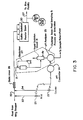
- Figure 3 is a schematic diagram of an alternative embodiment of the system illustrated in Figure 2.
- Generally speaking, the invention features a continuous pH control of a process stream. It is often desirable to control the pH of a continuous process stream by the addition of a reagent. The pH process is inherently non-linear by virtue of the logarithmic definition of pH. The non-linearityfor a specific process is affected by the type and concentration of buffers which are present in the process stream and which may be variable on a continuous basis. This non-linearity can impose stringent requirements on the pH control system's resolution, rangeability and dynamic response. In order to moderate the stringency of the control task, it is common practice to introduce a large backmixed vessel into the process stream as illustrated in the prior art system of Figure 1.
- The prior art system of Figure 1 features in the schematic diagram a conduit 10 for conveying an influent process stream. The stream is fed to a large backmixing vessel 11, from which it is discharged as treated effluent to the environment via
conduit 12. The backmixed stream is analyzed by apH analyzer 13, which controls apH feedback controller 14, which in turn actuates appropriate valves 15for adding a given amount of pH bufferto line 10, as shown. The sample of the treated effluent stream, after analysis in thepH analyzer 13 is returned to the process system as sample return at any convenient downstream location (e.g. for addition to the main treated effluent stream from conduit 12). - From a control standpoint the primary purpose for introducing the backmixed vessel is to reduce the dynamic gain of the process. The extent of the gain reduction is a function of the degree of backmixing. The backmixed vessel might also serve other process functions such as uniformly distributing the reagent, "averaging" the final pH of the process stream or providing holdup in the process system.
- Such a system is more fully described in the text of: Shimskey, F. G., pH and plon Control in Process and Waste Streams, John Wiley and Sons, New York, 1978.
- The invention as shown in Figure 2, features a process stream carried by a
conduit 20. A continuous sample is drawn fromconduit 20 vialine 21, which sample enters asmall backmixing vessel 22, as depicted. - A continuous pH analysis of the backmixed sample is performed by
analyzer 23, such as Uniloc Model 1003. Theanalyzer 23 feeds an electrical signal to afeedback controller 24, such as Honeywell TDC 2000 or Foxboro Spec 200, indicative of the instantaneous pH of the backmixed sample. Thefeedback controller 24 in response to the analyzer signal operatesappropriate valving 25 to add a pH buffer (reagent) into an upstream portion ofconduit 20, as illustrated. Astatic mixer 26, such as Komax 3D Mixer, Komax Systems Inc., Long Beach, California, U.S.A., is used to mix the reagent into the process stream, which flows as treated effluent to exit 27. - The replacement of a
small backmixing vessel 22 disposed in thesample stream 21, for a large backmixing vessel 11 disposed in the effluent stream (Figure 1) ensures a sizeable cost saving. Moreover, the design of the large vessel 11 is more complicated due to the need to contain hazardous gases freed in the reaction. - In addition, the use of a
small backmixing vessel 22 in the sample stream ensures a more complete backmixing, such that maximum gain reduction can be achieved for the inventive system. - With the typical arrangement illustrated in Figure 1, the reagent is added to the influent before entering the backmixed vessel. In addition to dispersing the reagent, the backmixed vessel decreases the dynamic gain of the process (i.e. averages the sample). Since the pH analyzer sample point is downstream of the backmixed vessel, the reduced dynamic process gain is what is seen by the pH feedback control system. Because of the reduced dynamic gain, stable control can only be achieved with reduced reagent delivery resolution and less dramatic non-linear gain in the feedback controller. With the invention, however, the reagent is dispersed by a static mixer upstream of the pH analyzer sample point (this also assures a representative sample). The sample is then backmixed resulting in a reduced dynamic gain as seen by the feedback control system with the previously stated benefits to the control system in terms of reduced requirements for reagent delivery resolution and controller gain characteristics.
- The treated effluent from the invention of Figure 2, unlike that of Figure 1, is not "averaged" (the pH along the effluent line may vary substantially) because of the absence of backmixing. This is typically not a problem since there is often some sort of downstream process capacity which will serve to "average" the instantaneous pH variations. When "averaged", however, the resultant final pH will be the same as seen by the pH analyzer (the desired control pH value).
- The concept of backmixing only an analyzer sample stream, rather than the entire process stream is applicable to control of any process where backmixing is necessary to achieve a dynamic gain reduction.
- This system features the addition of a downstream sulfite oxidation reaction basin or
alternative oxidation facilities 30. As depicted in Fig. 3, the influent process steam is a feed discharged from an NH3 stripper in which NH3 is removed from a water stream by steam "stripping" in a tower. - Caustic or acid is added upstream of the oxidation basin such that the effluent pH will be about 7. The holdup of the basic is on the order of 20 hours making normal feedback control impossible. The pH control technique of Figure 3, involves use of a
backmixing vessel 22 in the pHanalyzer sample line 21 as before. Arapid oxidation vessel 31 is added after thebackmixing vessel 22 in theanalyzer sample stream 21. Reagent is injected into thefeed line 20 vialines static mixer 26 which disperses the reagent and assures a representative analyzer sample. A small portion of the feed is taken into the sample system where it first passes through abackmixing vessel 22. The backmixing vessel provides a dynamic gain reduction which decreases the resolution and dynamic response requirements of the control system. The backmixing vessel would be designed for a nominal holdup (consistent with overall sample system dead time) and better than 90% backmixing. (If reagent addition were controlled based upon the pH at the outlet of the backmixing vessel, this would be the equivalent of controlling the outlet pH to theoxidation basin 30. Therefore, no automatic compensation would be made for the varying effect of acid formation). The sample then passes through anoxidation vessel 31, where complete (or nearly complete) oxidation is carried out with a brief (5-10 minute) holdup. The sample then goes to thepH analyzer 23. The pH analyzer signal is used in a feedback control scheme to regulate the reagent addition. The sample is returned to the process at a sample return point at some suitable downstream location. The remainder of the pH control system (controller 24 and reagent addition pumps or valves 25) can be designed to meet the requirements of this application. The oxidation basin feed sampiing and process pH simulation offers a unique solution to an otherwise difficult pH control problem. - The treated effluent passes via
conduit 27 to a biox facility where the effluent is further treated in the presence of biological agents. As shown in Fig. 3, the quality of the effluent inline 27 is monitored by means of a pH analyzer with a continuous recorder, indicated by reference "A(pH)/R". The latter pH analyzer is equipped with alarm devices for high pH (indicated as "AHA") and low pH (indicated by "ALA").
Claims (9)
Applications Claiming Priority (2)
| Application Number | Priority Date | Filing Date | Title |
|---|---|---|---|
| US308467 | 1981-10-05 | ||
| US06/308,467 US4762796A (en) | 1981-10-05 | 1981-10-05 | pH control of a process stream |
Publications (2)
| Publication Number | Publication Date |
|---|---|
| EP0076683A1 EP0076683A1 (en) | 1983-04-13 |
| EP0076683B1 true EP0076683B1 (en) | 1988-11-30 |
Family
ID=23194104
Family Applications (1)
| Application Number | Title | Priority Date | Filing Date |
|---|---|---|---|
| EP82305270A Expired EP0076683B1 (en) | 1981-10-05 | 1982-10-04 | Apparatus and method for controlling the ph of a continuous process stream |
Country Status (5)
| Country | Link |
|---|---|
| US (1) | US4762796A (en) |
| EP (1) | EP0076683B1 (en) |
| JP (1) | JPS5874184A (en) |
| CA (1) | CA1198971A (en) |
| DE (1) | DE3279256D1 (en) |
Families Citing this family (12)
| Publication number | Priority date | Publication date | Assignee | Title |
|---|---|---|---|---|
| US4648043A (en) * | 1984-05-07 | 1987-03-03 | Betz Laboratories, Inc. | Computerized system for feeding chemicals into water treatment system |
| GB8614530D0 (en) * | 1986-06-14 | 1986-07-23 | Clean Water Co Ltd | Liquid treatment process |
| DE3718338A1 (en) * | 1987-06-01 | 1989-01-05 | Karlsruhe Wiederaufarbeit | METHOD AND DEVICE FOR SOLVENT WASHING IN THE REPROCESSING OF IRRADIATED NUCLEAR FUELS |
| DE3723178C2 (en) * | 1987-07-14 | 1996-01-25 | Bodenseewerk Perkin Elmer Co | Method and device for flow injection analysis in combination with atomic absorption spectroscopy |
| GB2230619B (en) * | 1989-03-14 | 1993-07-14 | Philip Kerrison | Chemical dose control |
| DE4117382A1 (en) * | 1991-05-28 | 1992-12-03 | Metallgesellschaft Ag | METHOD FOR REGULATING THE PH VALUE OF AN ACID WASHING LIQUID |
| US5168065A (en) * | 1991-11-27 | 1992-12-01 | The Babcock & Wilcox Company | Forced oxidation monitoring and control system |
| US5202092A (en) * | 1991-12-03 | 1993-04-13 | Norcross Corporation | Device for monitoring the PH of water based inks |
| US5609180A (en) * | 1992-04-27 | 1997-03-11 | Burlington Chemical Co., Inc. | Liquid alkali system for fiber reactive dyeing |
| DE4300388C2 (en) * | 1993-01-09 | 1995-03-16 | Metallgesellschaft Ag | Process for the continuous adjustment and control of the pH of an acidic liquid, in which the continuous measurement of the pH takes place with a glass electrode |
| DE4335867A1 (en) * | 1993-10-21 | 1995-05-04 | Hans Dr Remstedt | Process for the simultaneous removal of sulphur oxides and nitrogen oxides from combustion exhaust gases in an ammonia scrubber |
| US9527010B2 (en) | 2009-09-25 | 2016-12-27 | Ge Healthcare Bio-Sciences Corp. | Separation system and method |
Family Cites Families (9)
| Publication number | Priority date | Publication date | Assignee | Title |
|---|---|---|---|---|
| US3069242A (en) * | 1958-02-25 | 1962-12-18 | Chemithon Corp | Sulfonation and sulfation apparatus |
| US3180699A (en) * | 1959-10-31 | 1965-04-27 | Ballestra Mario | Method for carrying out continuously the stoichiometric neutralization of a sulphonic acid |
| US3791793A (en) * | 1972-01-31 | 1974-02-12 | Leeds & Northrup Co | Adaptive feed forward-feedback control of the concentration of a selected ion of a solution |
| US4033871A (en) * | 1975-11-13 | 1977-07-05 | Paddock Of California, Inc. | Integrated monitor and control system for continuously monitoring and controlling pH and free halogen in swimming pool water |
| US4121767A (en) * | 1976-07-26 | 1978-10-24 | Richard Jensen | Mobile agricultural sprayer with additive concentration control |
| US4164547A (en) * | 1977-05-06 | 1979-08-14 | American Air Filter Company, Inc. | Process for removing sulfur dioxide in a wet scrubber |
| US4181951A (en) * | 1978-04-28 | 1980-01-01 | Jan Boeke | In-line pH and pIon controller |
| US4224283A (en) * | 1979-03-02 | 1980-09-23 | Phillips Petroleum Company | Purification of hydrocarbons |
| NL7902177A (en) * | 1979-03-20 | 1980-09-23 | Verder Vleuten Bv | Automatic metering of chemicals into swimming pools - with analysis of a mixed sample and using results to control chemical input |
-
1981
- 1981-10-05 US US06/308,467 patent/US4762796A/en not_active Expired - Lifetime
-
1982
- 1982-08-16 CA CA000409507A patent/CA1198971A/en not_active Expired
- 1982-10-04 DE DE8282305270T patent/DE3279256D1/en not_active Expired
- 1982-10-04 EP EP82305270A patent/EP0076683B1/en not_active Expired
- 1982-10-05 JP JP57174097A patent/JPS5874184A/en active Granted
Non-Patent Citations (1)
| Title |
|---|
| INSTRUMENTS & CONTROL SYSTEMS, vol.49, no.1, January 1976, Radnor (US) F.G. SHINSKEY: "Flue-gas scrubbing. Part II: Control systems", page 65 * |
Also Published As
| Publication number | Publication date |
|---|---|
| DE3279256D1 (en) | 1989-01-05 |
| US4762796A (en) | 1988-08-09 |
| EP0076683A1 (en) | 1983-04-13 |
| CA1198971A (en) | 1986-01-07 |
| JPH0221875B2 (en) | 1990-05-16 |
| JPS5874184A (en) | 1983-05-04 |
Similar Documents
| Publication | Publication Date | Title |
|---|---|---|
| EP0076683B1 (en) | Apparatus and method for controlling the ph of a continuous process stream | |
| US3674672A (en) | Multiparameter process solution analyzer-controller | |
| CA1186424A (en) | Break-point chlorination control system | |
| JP3168217B2 (en) | Method and apparatus for supplying gas to ultra-high precision analyzer | |
| JPH0540112A (en) | Analyzing apparatus of component of sample liquid | |
| WO2018163475A1 (en) | Ballast water measurement device, ship provided with ballast water measurement device, and ballast water measurement method | |
| CA2077206A1 (en) | Corrosion control for wet oxidation systems | |
| CN109078478B (en) | Flue gas deacidification treatment system and application thereof | |
| US5861316A (en) | Continuous emission monitoring system | |
| DE2935120C2 (en) | Process for optimizing the air input into a waste water / activated sludge mixture | |
| DE10352638B4 (en) | Process and plant for gas purification | |
| US4126550A (en) | Flash reactor | |
| US4968436A (en) | Method for the treatment of sewage containing nitrites | |
| EP0328444A2 (en) | Equipment and process for dissolving gas in liquids | |
| JPS633323B2 (en) | ||
| US4795713A (en) | Auto-digestor | |
| JP2003236570A (en) | Method and apparatus for hydrothermal reaction | |
| US6290850B1 (en) | Method for controlling aeration systems of biological tanks treating waste water | |
| KR19990052241A (en) | Automatic control method of wastewater in wastewater using carbon dioxide-containing flue gas | |
| CN220300511U (en) | Full-automatic break point chlorination equipment | |
| CN114025864A (en) | Optimization of wet scrubber process flow by on-line measurement and control of entrained gas in scrubber liquid | |
| JPH03272464A (en) | Apparatus for automatically and continuously analyzing cod in waste water | |
| JPS60143825A (en) | Reaction and maturation apparatus | |
| SU1006386A1 (en) | Apparatus for automatically controlling neutralization of industrial acid effluents | |
| SU1604749A1 (en) | Method of automatic control of process of cleaning of effluents from hexavalent chromium |
Legal Events
| Date | Code | Title | Description |
|---|---|---|---|
| PUAI | Public reference made under article 153(3) epc to a published international application that has entered the european phase |
Free format text: ORIGINAL CODE: 0009012 |
|
| AK | Designated contracting states |
Designated state(s): DE FR GB IT |
|
| 17P | Request for examination filed |
Effective date: 19830921 |
|
| GRAA | (expected) grant |
Free format text: ORIGINAL CODE: 0009210 |
|
| AK | Designated contracting states |
Kind code of ref document: B1 Designated state(s): DE FR GB IT |
|
| ITF | It: translation for a ep patent filed |
Owner name: ING. C. GREGORJ S.P.A. |
|
| REF | Corresponds to: |
Ref document number: 3279256 Country of ref document: DE Date of ref document: 19890105 |
|
| ET | Fr: translation filed | ||
| PLBE | No opposition filed within time limit |
Free format text: ORIGINAL CODE: 0009261 |
|
| STAA | Information on the status of an ep patent application or granted ep patent |
Free format text: STATUS: NO OPPOSITION FILED WITHIN TIME LIMIT |
|
| 26N | No opposition filed | ||
| ITTA | It: last paid annual fee | ||
| PGFP | Annual fee paid to national office [announced via postgrant information from national office to epo] |
Ref country code: GB Payment date: 20011004 Year of fee payment: 20 |
|
| PGFP | Annual fee paid to national office [announced via postgrant information from national office to epo] |
Ref country code: FR Payment date: 20011005 Year of fee payment: 20 |
|
| PGFP | Annual fee paid to national office [announced via postgrant information from national office to epo] |
Ref country code: DE Payment date: 20011030 Year of fee payment: 20 |
|
| REG | Reference to a national code |
Ref country code: GB Ref legal event code: IF02 |
|
| PG25 | Lapsed in a contracting state [announced via postgrant information from national office to epo] |
Ref country code: GB Free format text: LAPSE BECAUSE OF EXPIRATION OF PROTECTION Effective date: 20021003 |
|
| REG | Reference to a national code |
Ref country code: GB Ref legal event code: PE20 Effective date: 20021003 |