EP0076554A2 - Apparatus for moulding articles from concrete or another material - Google Patents
Apparatus for moulding articles from concrete or another material Download PDFInfo
- Publication number
- EP0076554A2 EP0076554A2 EP82201241A EP82201241A EP0076554A2 EP 0076554 A2 EP0076554 A2 EP 0076554A2 EP 82201241 A EP82201241 A EP 82201241A EP 82201241 A EP82201241 A EP 82201241A EP 0076554 A2 EP0076554 A2 EP 0076554A2
- Authority
- EP
- European Patent Office
- Prior art keywords
- scouring
- mould
- concrete
- filling
- moulding
- Prior art date
- Legal status (The legal status is an assumption and is not a legal conclusion. Google has not performed a legal analysis and makes no representation as to the accuracy of the status listed.)
- Withdrawn
Links
- 239000004567 concrete Substances 0.000 title claims abstract description 33
- 238000000465 moulding Methods 0.000 title claims abstract description 10
- 239000000463 material Substances 0.000 title description 5
- 238000009991 scouring Methods 0.000 claims abstract description 40
- 239000000203 mixture Substances 0.000 claims abstract description 11
- 239000002184 metal Substances 0.000 claims description 3
- 239000011121 hardwood Substances 0.000 claims description 2
- 229910001220 stainless steel Inorganic materials 0.000 claims description 2
- 239000010935 stainless steel Substances 0.000 claims description 2
- 238000005266 casting Methods 0.000 claims 2
- 239000007787 solid Substances 0.000 claims 2
- 238000004519 manufacturing process Methods 0.000 description 5
- 238000010276 construction Methods 0.000 description 3
- 230000000694 effects Effects 0.000 description 2
- 230000004438 eyesight Effects 0.000 description 2
- 239000004033 plastic Substances 0.000 description 2
- 239000002023 wood Substances 0.000 description 2
- 241000283690 Bos taurus Species 0.000 description 1
- 230000002860 competitive effect Effects 0.000 description 1
- 230000008878 coupling Effects 0.000 description 1
- 238000010168 coupling process Methods 0.000 description 1
- 238000005859 coupling reaction Methods 0.000 description 1
- 230000001419 dependent effect Effects 0.000 description 1
- 238000001035 drying Methods 0.000 description 1
- 239000011178 precast concrete Substances 0.000 description 1
- 230000002787 reinforcement Effects 0.000 description 1
Images

Classifications
-
- B—PERFORMING OPERATIONS; TRANSPORTING
- B28—WORKING CEMENT, CLAY, OR STONE
- B28B—SHAPING CLAY OR OTHER CERAMIC COMPOSITIONS; SHAPING SLAG; SHAPING MIXTURES CONTAINING CEMENTITIOUS MATERIAL, e.g. PLASTER
- B28B1/00—Producing shaped prefabricated articles from the material
- B28B1/29—Producing shaped prefabricated articles from the material by profiling or strickling the material in open moulds or on moulding surfaces
-
- B—PERFORMING OPERATIONS; TRANSPORTING
- B28—WORKING CEMENT, CLAY, OR STONE
- B28B—SHAPING CLAY OR OTHER CERAMIC COMPOSITIONS; SHAPING SLAG; SHAPING MIXTURES CONTAINING CEMENTITIOUS MATERIAL, e.g. PLASTER
- B28B11/00—Apparatus or processes for treating or working the shaped or preshaped articles
- B28B11/08—Apparatus or processes for treating or working the shaped or preshaped articles for reshaping the surface, e.g. smoothing, roughening, corrugating, making screw-threads
- B28B11/0845—Apparatus or processes for treating or working the shaped or preshaped articles for reshaping the surface, e.g. smoothing, roughening, corrugating, making screw-threads for smoothing
-
- B—PERFORMING OPERATIONS; TRANSPORTING
- B28—WORKING CEMENT, CLAY, OR STONE
- B28B—SHAPING CLAY OR OTHER CERAMIC COMPOSITIONS; SHAPING SLAG; SHAPING MIXTURES CONTAINING CEMENTITIOUS MATERIAL, e.g. PLASTER
- B28B11/00—Apparatus or processes for treating or working the shaped or preshaped articles
- B28B11/18—Apparatus or processes for treating or working the shaped or preshaped articles for removing burr
Definitions
- the invention relates especially to systems for the production of precast products from concrete and similar moulding materials.
- precast concrete products are, possibly enforced, cable troughs, cattle slats, posts, bumper blocks, manholes, lintels, preformed wall parts, building panels and many others.
- This type of equipment can be constructed for a large number of applications in such a way that no special foundations are required and that they can easily be assembled and moved to another location.
- Filling of the mold can be done through a charging hopper which itself can be filled in any known way, for instance by a belt conveyor or with some lever apparatus.
- the mould may be provided when needed with a suitable reinforcement. After opening the locking members of the charging funnel the concrete mix falls down into the mould. After vibration and leveling a pallet may be positioned on top of the mould frame and clamped to it. After turning upside down the mould and releasing the clamps the shaped concrete remains on the pallet.
- the pallet may be piled up to a predetermined height and moved to the drying space.
- the concrete moulding apparatus is characterized by an equalizing beam which is coupled to a drive mechanism, and can be moved in a horizontal as well as in a vertical direction and has at its lower side a free horizontal surface adapted to the upper surface of the mould, the drive mechanism being provided with one or more eccentrics enabling the lower beam surface to carry out circular movements over the mould surface while the beam moves over it.
- Supply of new concrete mix, movements of the beam and the removal system of the mould are mutually coordinated.
- the scouring system 20 proper shows the following parts: (figures 1 and 2)
- the eccentric axles 3 start moving.
- the lower eccentric part 14 of axle 3 can rotate freely in casing 4 of support 1.
- the latter starts moving and in this way exercises a scouring action with respect to frame 7 and the surface of mould 10, situated below the scouring surface 25 of scouring beam 2. All points of the scouring beam are carrying out a circular movement.
- the diamecer of the circles corresponds to the eccentricity of driving shaft 3. It is this type of moving that smoothes efficiently the surface of the concrete filling in the mould.
- the screed mechanism must also be movable in a horizontal direction over the surface of the concrete in the mould in order to remove the concrete excess.
- the screed mechanism should also be movable in a vertical direction. During this vertical movement the scouring surface 25 must maintain its horizontal extension. To this effect use can be made of a certain co-ordination with the movements of the filling device 13 combined with a parallelogram type of construction for driving.
- the filling carriage 16 is filled from filling bunker 13.
- the carriage moves over mould 9 and fills it to the brim.
- the dosing valve 17 moves to a predetermined height.
- the filling carriage moves back again and in this way doses just a little bit too much.
- the valve 17 closes on reaching the end of the mould and all excess of fill material is taken along.
- the vibrational treatment starts.
- the dosing valve 17 and valve 18 move upwards and filling carriage 12 moves forwards over the mould. This time the concrete is not taken along but remains on table 15.
- the scouring system moves downward to the mould surface and starts scouring.
- This solution has been mainly developed in order to provide existing machines with the scouring system according to the invention.
- the scouring system 2 descends on the mould and starts scouring.
- the upper parallelogram 23 moves the scouring system forward and backward over the mould surface. This results in closing the surface structure.
- the scouring beam 2 may consist wholly or in part of metal, wood or plastic.
- the scouring surface 25 There is also a wide choice for the scouring surface 25. The best results were obtained with hard wood and stainless steel.
- the purpose is to obtain an effectively scouring surface of high stability that may be formed and/or shaped in any known way. Preferably it is a closed plane that is not interrupted by open spots or other disturbances. Satisfactory results were, however, also obtained with scouring surfaces of some other shape such as a partly open frame.
Landscapes
- Engineering & Computer Science (AREA)
- Chemical & Material Sciences (AREA)
- Ceramic Engineering (AREA)
- Mechanical Engineering (AREA)
- Structural Engineering (AREA)
- Manufacturing & Machinery (AREA)
- Devices For Post-Treatments, Processing, Supply, Discharge, And Other Processes (AREA)
- On-Site Construction Work That Accompanies The Preparation And Application Of Concrete (AREA)
- Moulds, Cores, Or Mandrels (AREA)
Abstract
A continuous moulding system in which a wet concrete mixture is filled into a mould (9,10), vibrated and solidified to a shaped concrete product. The mould (9,10) has at least one free horizontal upper surface. After filling the mould (9,10) excess concrete must be removed and the surface must be treated to obtain a dense and smooth structure.
To reach this use is made of a scouring beam (2) that can be moved in a horizontal and a vertical direction. It has a lower surface (25) that can be moved in a straight as well as in a slightly circular path.
All movements of the beam (2) can be derived from and co-ordinated with the driving means of the moulding equipment.
Description
- The invention relates especially to systems for the production of precast products from concrete and similar moulding materials.
- The manufacture of concrete products which may be of large dimensions and which are more and more used for building purposes is an extensive matter. It is largely an item of competitive mass-production and requires considerable investment and high labor expenses.
- Examples of precast concrete products are, possibly enforced, cable troughs, cattle slats, posts, bumper blocks, manholes, lintels, preformed wall parts, building panels and many others.
- The various objects and advantages of the invention will be more apparent from the following detailed description of typical embodiments thereof in the application to stationary-moulding machines in which, if desired, the supply of the molds, turning upside down and removal of the finished product and of the empty mold may be carried out automatically.
- This type of equipment can be constructed for a large number of applications in such a way that no special foundations are required and that they can easily be assembled and moved to another location.
- Filling of the mold can be done through a charging hopper which itself can be filled in any known way, for instance by a belt conveyor or with some lever apparatus.
- The mould may be provided when needed with a suitable reinforcement. After opening the locking members of the charging funnel the concrete mix falls down into the mould. After vibration and leveling a pallet may be positioned on top of the mould frame and clamped to it. After turning upside down the mould and releasing the clamps the shaped concrete remains on the pallet.
- The pallet, possibly together with other product carrying pallets, may be piled up to a predetermined height and moved to the drying space.
- Now, after setting of the concrete mass in the mould and before turning, it will be necessary to remove the excess concrete and to finish the concrete surface. Removal of the concrete excess is normally done by hand with a leveling device or a kind of shovel. Even more effort, however, is required for the finishing of the concrete surface. As a rule this is done with a small wooden scouring board which is moved over the concrete surface till it is estimated by vision to be sufficiently flat.
- It is clear that these manual actions fall under the category of heavy labour and moreover extend the cycletime of the production. The result is highly dependent on the experience, insight and endeavour of the handicraftsman.
- Attempts to move the known scouring board over the concrete surface or to replace it by two transverse cross-pieces moving over the concrete surface did not result in the desired concrete quality and were difficult to control.
- The concrete moulding apparatus according to the invention is characterized by an equalizing beam which is coupled to a drive mechanism, and can be moved in a horizontal as well as in a vertical direction and has at its lower side a free horizontal surface adapted to the upper surface of the mould, the drive mechanism being provided with one or more eccentrics enabling the lower beam surface to carry out circular movements over the mould surface while the beam moves over it. Supply of new concrete mix, movements of the beam and the removal system of the mould are mutually coordinated.
- The invention is illustrated by some typical embodiments shown in figures 1 - 4. The figures present the following:
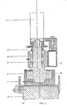
- figure 1 a vertical section of the essential moulding part of a concrete moulding apparatus;
- figure 2 a vertical section perpendicular to the section of figure 1 at the motor portion;
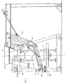
- figure 3 a vertical section of an existing moulding apparatus with which the equalizing and finishing system according to the invention is combined;
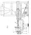
- figure 4 a section of a construction in which the supply carriage with concrete mix can move both over a fixed table behind the mould as well as over the mould surface.
- The
scouring system 20 proper shows the following parts: (figures 1 and 2) - 1. A
support 1 for the scouringbeam 2 with a fast acting pinching device. - 2-. The
scouring beam 2 which for example may exist of wood, plastic or metal. - 3. Two
eccentric driving axles - 4. A bearing case 4 connected with
beam 1. - 5. A bearing case 5 connected with frame 7.
- 6. A
driving motor 6. - 7. Frame 7.
- 8. Chainwheel 11 with chain 12.
- As soon as the driving
motor 6 starts rotation theeccentric axles 3 start moving. The lowereccentric part 14 ofaxle 3 can rotate freely in casing 4 ofsupport 1. The latter starts moving and in this way exercises a scouring action with respect to frame 7 and the surface ofmould 10, situated below thescouring surface 25 of scouringbeam 2. All points of the scouring beam are carrying out a circular movement. The diamecer of the circles corresponds to the eccentricity of drivingshaft 3. It is this type of moving that smoothes efficiently the surface of the concrete filling in the mould. - The screed mechanism must also be movable in a horizontal direction over the surface of the concrete in the mould in order to remove the concrete excess. To fill the mould and to be able to use moulds of different height in one and the same apparatus the screed mechanism should also be movable in a vertical direction. During this vertical movement the
scouring surface 25 must maintain its horizontal extension. To this effect use can be made of a certain co-ordination with the movements of thefilling device 13 combined with a parallelogram type of construction for driving. - This can be realized in several different ways, for instance as follows:
- A. The screed mechanism forms part of a filling carriage that fills the mould.
- B. The screed mechanism forms part of a filling funnel that moves above the mould.
- C. The screed mechanism forms part of a fixed filling funnel.
- In case of the system sub A an adjustable quantity of concrete composition is dosed into the mould. Then vibration starts.
- This filling system shows the following parts: (figure 4)
- 1. A fixed table 15 behind the
mould 9. - 2. A hydraulically driven filling
carriage 16. - 3.
Valve 18 opening the carriage on one side. - 4. A sliding
valve 17. - 5. Parallelogram
type lift mechanism 19, serving the scouring system, - 6. Scouring
system 20. - 7.
Supply bunker 13. - Besides the mechanical leveling the required quantity of concrete is automatically introduced at the correct time.
- The filling
carriage 16 is filled from fillingbunker 13. The carriage moves overmould 9 and fills it to the brim. Thedosing valve 17 moves to a predetermined height. - The filling carriage moves back again and in this way doses just a little bit too much. The
valve 17 closes on reaching the end of the mould and all excess of fill material is taken along. - The vibrational treatment starts. The
dosing valve 17 andvalve 18 move upwards and filling carriage 12 moves forwards over the mould. This time the concrete is not taken along but remains on table 15. The scouring system moves downward to the mould surface and starts scouring. - Continually scouring the filling carriage moves slowly and repeatedly over the mould and then returns to its starting position. The small quantity of oversupplied concrete is carried along to table 15.
- Filling funnel with the scouring system mounted thereon. In this case the supply bunker itself moves over the mould. By pneumatically acting on the valves the concrete mix is dosed into the mould by eyesight and distributed by hand. Then the scouring system moves downward to the mould surface and starts scouring. The filling funnel travels to and fro slowly. Excess of concrete mix is shoved away from the mould surface. The concrete in the mould is finished to a dense and smooth surface.
- Here one has a filling
funnel 24 in fixed position with fastened thereto the scouring system. (figure 3) The following parts are noted: - 1. Scouring
system 20 as described under sub A. - 2.
Parallelogram mechanism 22 to lower the scouring system to the mould surface. - 3. Parallelogram-
mechanism 23 to move the scouring system over the mould surface forwards and backwards. - 4.
Construction 21 for attachment and mutually coupling. - 5.
Supply bunker 13. - This solution has been mainly developed in order to provide existing machines with the scouring system according to the invention.
- It works as follows:
- By means of pneumatically operated valves the concrete mix from
bunker 13 is dosed into themould 9. - The scouring
system 2 descends on the mould and starts scouring. Theupper parallelogram 23 moves the scouring system forward and backward over the mould surface. This results in closing the surface structure. - It is clear that the invention is not limited to the application examples given above. Energy supply along electric, pneumatic or hydraulic route can be replaced by any other energy form to attain the desired effect.
- Highly important is that apart from an increased production rate with less manual work a result is obtained that at least equalizes present best results in industry and even, as a rule, improves product quality.
- Material can be replaced by other material in different ways. So the scouring
beam 2 may consist wholly or in part of metal, wood or plastic. There is also a wide choice for the scouringsurface 25. The best results were obtained with hard wood and stainless steel. The purpose is to obtain an effectively scouring surface of high stability that may be formed and/or shaped in any known way. Preferably it is a closed plane that is not interrupted by open spots or other disturbances. Satisfactory results were, however, also obtained with scouring surfaces of some other shape such as a partly open frame.
Claims (6)
1. Apparatus for moulding solid articles from casting compositions, especially concrete mixtures, which can be formed into solid articles in the mould (9,10), characterized by
a scouring system (20), formed by a scouring beam (2) coupled to driving means which is movable both in a horizontal and vertical direction and has at its horizontal bottom side a scouring surface (25) adapted to the upper side of the mould (9,10), said beam (2) moreover being coupled to eccentric means (3,4,5,14) enabling to impart small circular movements to the scouring surface (25) one and the other co-ordinated with the supplying and controlling means (13,16,17,18,24) of the apparatus for the casting composition.
a scouring system (20), formed by a scouring beam (2) coupled to driving means which is movable both in a horizontal and vertical direction and has at its horizontal bottom side a scouring surface (25) adapted to the upper side of the mould (9,10), said beam (2) moreover being coupled to eccentric means (3,4,5,14) enabling to impart small circular movements to the scouring surface (25) one and the other co-ordinated with the supplying and controlling means (13,16,17,18,24) of the apparatus for the casting composition.
2. Apparatus according to claim 1,
characterized by
a scouring beam (2) carrying on its upper side one or more eccentric driving shafts (3,14).
characterized by
a scouring beam (2) carrying on its upper side one or more eccentric driving shafts (3,14).
3. Apparatus according to claim 2,
characterized by
a chain wheel (11) and chain (12) to garantee a synchronic moving of the eccentric means (3,14).
characterized by
a chain wheel (11) and chain (12) to garantee a synchronic moving of the eccentric means (3,14).
4. Apparatus according to claims 1 - 3,
characterized by
a scouring element (2) with a flat non-interrupted scouring surface (25).
characterized by
a scouring element (2) with a flat non-interrupted scouring surface (25).
5. Apparatus according to claims 1 - 4,
characterized in
that the scouring surface (25) consists of hard wood.
characterized in
that the scouring surface (25) consists of hard wood.
6. Apparatus according to claims 1 - 4,
characterized by
a scouring surface (25) of metal, especially stainless steel. ---
characterized by
a scouring surface (25) of metal, especially stainless steel. ---
Applications Claiming Priority (2)
| Application Number | Priority Date | Filing Date | Title |
|---|---|---|---|
| NL8104555 | 1981-10-07 | ||
| NL8104555A NL8104555A (en) | 1981-10-07 | 1981-10-07 | APPARATUS FOR POURING ARTICLES FROM CONCRETE OR OTHER MATERIAL. |
Publications (2)
| Publication Number | Publication Date |
|---|---|
| EP0076554A2 true EP0076554A2 (en) | 1983-04-13 |
| EP0076554A3 EP0076554A3 (en) | 1984-04-18 |
Family
ID=19838179
Family Applications (1)
| Application Number | Title | Priority Date | Filing Date |
|---|---|---|---|
| EP82201241A Withdrawn EP0076554A3 (en) | 1981-10-07 | 1982-10-06 | Apparatus for moulding articles from concrete or another material |
Country Status (2)
| Country | Link |
|---|---|
| EP (1) | EP0076554A3 (en) |
| NL (1) | NL8104555A (en) |
Families Citing this family (1)
| Publication number | Priority date | Publication date | Assignee | Title |
|---|---|---|---|---|
| CN108422539B (en) * | 2017-08-12 | 2020-05-22 | 中民筑友科技投资有限公司 | BIM-based component finishing method and device |
Family Cites Families (4)
| Publication number | Priority date | Publication date | Assignee | Title |
|---|---|---|---|---|
| US1610266A (en) * | 1926-08-14 | 1926-12-14 | Davis Roy Paul Miller | Slicker |
| US1779209A (en) * | 1928-01-06 | 1930-10-21 | Roy P M Davis | Brickmaking machine |
| FR1097677A (en) * | 1953-02-18 | 1955-07-08 | Scraper mechanism for concrete block molding machines | |
| DE2137879A1 (en) * | 1971-07-29 | 1973-02-08 | Wenker Karl | RAKLER |
-
1981
- 1981-10-07 NL NL8104555A patent/NL8104555A/en not_active Application Discontinuation
-
1982
- 1982-10-06 EP EP82201241A patent/EP0076554A3/en not_active Withdrawn
Also Published As
| Publication number | Publication date |
|---|---|
| NL8104555A (en) | 1983-05-02 |
| EP0076554A3 (en) | 1984-04-18 |
Similar Documents
| Publication | Publication Date | Title |
|---|---|---|
| US3679340A (en) | Apparatus for forming building blocks | |
| CN109773959B (en) | Formwork machine for reinforced concrete structure | |
| US3833331A (en) | Apparatus for forming building blocks | |
| CN109877275B (en) | Sand mold 3D printer adopting double-frame lifting device | |
| EP0433591A2 (en) | Method and means for forming blocks from concrete mix at a high production rate and with high shape definition, and the product obtained | |
| US3002249A (en) | Machine for the manufacture of concrete building units | |
| CN1984758B (en) | Process system for manufacturing multi-layer concrete brick with decorative surface | |
| EP0076554A2 (en) | Apparatus for moulding articles from concrete or another material | |
| US3822794A (en) | Plant for filling molding cavities arranged in one or more bays | |
| GB1292286A (en) | Improvements in or relating to the manufacture of building elements | |
| US4226820A (en) | Method of and apparatus for forming an article from a mixture of a solidifying plastic material and a large portion of filler material | |
| CN209718053U (en) | Multistage feeding oscillatory type concrete precast block process equipment | |
| EP1802430B1 (en) | Apparatus for distributing in a thin layer a mix based on agglomerate stone or ceramic material | |
| US3520348A (en) | Fill carriages for automatic matchplate moulding machines | |
| US3006053A (en) | Masonry block apparatus | |
| US1846290A (en) | Apparatus for making roof tiles | |
| US3553798A (en) | Apparatus for producing precast concrete members | |
| US4334851A (en) | Concrete forming apparatus | |
| DE807259C (en) | Method and device for the mass production of concrete goods | |
| CN206718130U (en) | Carbon block forming machine with relative movement formula cloth, flat material device | |
| EP0415435B1 (en) | Apparatus for making simulated stone concrete blocks | |
| US1740711A (en) | Automatic brick-making machine and apparatus | |
| SU1011383A1 (en) | Concrete-laying machine | |
| CN104760116B (en) | Precast concrete semi-automatic forming device | |
| US2314577A (en) | Cement block molding machine |
Legal Events
| Date | Code | Title | Description |
|---|---|---|---|
| PUAI | Public reference made under article 153(3) epc to a published international application that has entered the european phase |
Free format text: ORIGINAL CODE: 0009012 |
|
| AK | Designated contracting states |
Designated state(s): BE DE FR GB IT NL |
|
| PUAL | Search report despatched |
Free format text: ORIGINAL CODE: 0009013 |
|
| AK | Designated contracting states |
Designated state(s): BE DE FR GB IT NL |
|
| STAA | Information on the status of an ep patent application or granted ep patent |
Free format text: STATUS: THE APPLICATION IS DEEMED TO BE WITHDRAWN |
|
| 18D | Application deemed to be withdrawn |
Effective date: 19850329 |