EP0076366B1 - Multilayer tubular body with uncentered barrier layer - Google Patents
Multilayer tubular body with uncentered barrier layer Download PDFInfo
- Publication number
- EP0076366B1 EP0076366B1 EP82106584A EP82106584A EP0076366B1 EP 0076366 B1 EP0076366 B1 EP 0076366B1 EP 82106584 A EP82106584 A EP 82106584A EP 82106584 A EP82106584 A EP 82106584A EP 0076366 B1 EP0076366 B1 EP 0076366B1
- Authority
- EP
- European Patent Office
- Prior art keywords
- percent
- barrier layer
- article
- layer
- weight percent
- Prior art date
- Legal status (The legal status is an assumption and is not a legal conclusion. Google has not performed a legal analysis and makes no representation as to the accuracy of the status listed.)
- Expired
Links
- 230000004888 barrier function Effects 0.000 title claims description 59
- 238000000034 method Methods 0.000 claims abstract description 22
- 229920000642 polymer Polymers 0.000 claims abstract description 14
- 229920001328 Polyvinylidene chloride Polymers 0.000 claims abstract description 13
- 230000035699 permeability Effects 0.000 claims abstract description 13
- 239000005033 polyvinylidene chloride Substances 0.000 claims abstract description 13
- 230000015572 biosynthetic process Effects 0.000 claims abstract description 8
- NLHHRLWOUZZQLW-UHFFFAOYSA-N Acrylonitrile Chemical compound C=CC#N NLHHRLWOUZZQLW-UHFFFAOYSA-N 0.000 claims abstract description 3
- 239000010410 layer Substances 0.000 claims description 127
- 229920001577 copolymer Polymers 0.000 claims description 22
- -1 polypropylene Polymers 0.000 claims description 16
- VGGSQFUCUMXWEO-UHFFFAOYSA-N Ethene Chemical compound C=C VGGSQFUCUMXWEO-UHFFFAOYSA-N 0.000 claims description 13
- 239000005977 Ethylene Substances 0.000 claims description 13
- 239000012815 thermoplastic material Substances 0.000 claims description 13
- 239000000203 mixture Substances 0.000 claims description 12
- 239000004743 Polypropylene Substances 0.000 claims description 9
- 229920001155 polypropylene Polymers 0.000 claims description 9
- 230000015556 catabolic process Effects 0.000 claims description 6
- 238000006731 degradation reaction Methods 0.000 claims description 6
- XTXRWKRVRITETP-UHFFFAOYSA-N Vinyl acetate Chemical compound CC(=O)OC=C XTXRWKRVRITETP-UHFFFAOYSA-N 0.000 claims description 5
- 239000012790 adhesive layer Substances 0.000 claims description 5
- JIGUQPWFLRLWPJ-UHFFFAOYSA-N Ethyl acrylate Chemical compound CCOC(=O)C=C JIGUQPWFLRLWPJ-UHFFFAOYSA-N 0.000 claims description 4
- 238000004519 manufacturing process Methods 0.000 claims description 4
- PNJWIWWMYCMZRO-UHFFFAOYSA-N pent‐4‐en‐2‐one Natural products CC(=O)CC=C PNJWIWWMYCMZRO-UHFFFAOYSA-N 0.000 claims description 4
- 239000013047 polymeric layer Substances 0.000 claims description 4
- 238000010791 quenching Methods 0.000 claims description 4
- 230000000171 quenching effect Effects 0.000 claims description 4
- CFVWNXQPGQOHRJ-UHFFFAOYSA-N 2-methylpropyl prop-2-enoate Chemical compound CC(C)COC(=O)C=C CFVWNXQPGQOHRJ-UHFFFAOYSA-N 0.000 claims description 3
- 239000004709 Chlorinated polyethylene Substances 0.000 claims description 3
- ZAMOUSCENKQFHK-UHFFFAOYSA-N Chlorine atom Chemical compound [Cl] ZAMOUSCENKQFHK-UHFFFAOYSA-N 0.000 claims description 3
- 239000004793 Polystyrene Substances 0.000 claims description 3
- MTAZNLWOLGHBHU-UHFFFAOYSA-N butadiene-styrene rubber Chemical compound C=CC=C.C=CC1=CC=CC=C1 MTAZNLWOLGHBHU-UHFFFAOYSA-N 0.000 claims description 3
- 229910052801 chlorine Inorganic materials 0.000 claims description 3
- 239000000460 chlorine Substances 0.000 claims description 3
- 229920000728 polyester Polymers 0.000 claims description 3
- 229920000098 polyolefin Polymers 0.000 claims description 3
- 229920002223 polystyrene Polymers 0.000 claims description 3
- 229920006001 poly(vinyl alcohol-co-ethylene) Polymers 0.000 claims 2
- 229920000131 polyvinylidene Polymers 0.000 claims 1
- 239000000463 material Substances 0.000 abstract description 44
- 229920001169 thermoplastic Polymers 0.000 abstract description 12
- 239000004416 thermosoftening plastic Substances 0.000 abstract description 12
- 230000008569 process Effects 0.000 abstract description 4
- 229920002554 vinyl polymer Polymers 0.000 abstract description 3
- 230000009467 reduction Effects 0.000 abstract description 2
- 125000000391 vinyl group Chemical group [H]C([*])=C([H])[H] 0.000 abstract 1
- 239000007789 gas Substances 0.000 description 19
- 239000003292 glue Substances 0.000 description 9
- OEPOKWHJYJXUGD-UHFFFAOYSA-N 2-(3-phenylmethoxyphenyl)-1,3-thiazole-4-carbaldehyde Chemical compound O=CC1=CSC(C=2C=C(OCC=3C=CC=CC=3)C=CC=2)=N1 OEPOKWHJYJXUGD-UHFFFAOYSA-N 0.000 description 7
- 238000000071 blow moulding Methods 0.000 description 5
- 239000002131 composite material Substances 0.000 description 5
- 238000001816 cooling Methods 0.000 description 5
- 238000000354 decomposition reaction Methods 0.000 description 5
- KAKZBPTYRLMSJV-UHFFFAOYSA-N Butadiene Chemical compound C=CC=C KAKZBPTYRLMSJV-UHFFFAOYSA-N 0.000 description 4
- BZHJMEDXRYGGRV-UHFFFAOYSA-N Vinyl chloride Chemical compound ClC=C BZHJMEDXRYGGRV-UHFFFAOYSA-N 0.000 description 4
- 239000000853 adhesive Substances 0.000 description 4
- 230000001070 adhesive effect Effects 0.000 description 4
- 238000002844 melting Methods 0.000 description 4
- 230000008018 melting Effects 0.000 description 4
- 229920003023 plastic Polymers 0.000 description 4
- 239000004033 plastic Substances 0.000 description 4
- 239000011347 resin Substances 0.000 description 4
- 229920005989 resin Polymers 0.000 description 4
- 238000001125 extrusion Methods 0.000 description 3
- QQONPFPTGQHPMA-UHFFFAOYSA-N propylene Natural products CC=C QQONPFPTGQHPMA-UHFFFAOYSA-N 0.000 description 3
- 125000004805 propylene group Chemical group [H]C([H])([H])C([H])([*:1])C([H])([H])[*:2] 0.000 description 3
- 238000007789 sealing Methods 0.000 description 3
- MYRTYDVEIRVNKP-UHFFFAOYSA-N 1,2-Divinylbenzene Chemical compound C=CC1=CC=CC=C1C=C MYRTYDVEIRVNKP-UHFFFAOYSA-N 0.000 description 2
- VXNZUUAINFGPBY-UHFFFAOYSA-N 1-Butene Chemical compound CCC=C VXNZUUAINFGPBY-UHFFFAOYSA-N 0.000 description 2
- ZGEGCLOFRBLKSE-UHFFFAOYSA-N 1-Heptene Chemical compound CCCCCC=C ZGEGCLOFRBLKSE-UHFFFAOYSA-N 0.000 description 2
- LIKMAJRDDDTEIG-UHFFFAOYSA-N 1-hexene Chemical compound CCCCC=C LIKMAJRDDDTEIG-UHFFFAOYSA-N 0.000 description 2
- KWKAKUADMBZCLK-UHFFFAOYSA-N 1-octene Chemical compound CCCCCCC=C KWKAKUADMBZCLK-UHFFFAOYSA-N 0.000 description 2
- BAPJBEWLBFYGME-UHFFFAOYSA-N Methyl acrylate Chemical compound COC(=O)C=C BAPJBEWLBFYGME-UHFFFAOYSA-N 0.000 description 2
- VVQNEPGJFQJSBK-UHFFFAOYSA-N Methyl methacrylate Chemical compound COC(=O)C(C)=C VVQNEPGJFQJSBK-UHFFFAOYSA-N 0.000 description 2
- 239000004698 Polyethylene Substances 0.000 description 2
- PPBRXRYQALVLMV-UHFFFAOYSA-N Styrene Chemical compound C=CC1=CC=CC=C1 PPBRXRYQALVLMV-UHFFFAOYSA-N 0.000 description 2
- 230000009471 action Effects 0.000 description 2
- 239000004840 adhesive resin Substances 0.000 description 2
- 229920006223 adhesive resin Polymers 0.000 description 2
- 150000001336 alkenes Chemical class 0.000 description 2
- 230000008021 deposition Effects 0.000 description 2
- 230000000694 effects Effects 0.000 description 2
- 230000006872 improvement Effects 0.000 description 2
- 239000011159 matrix material Substances 0.000 description 2
- 239000000178 monomer Substances 0.000 description 2
- YWAKXRMUMFPDSH-UHFFFAOYSA-N pentene Chemical compound CCCC=C YWAKXRMUMFPDSH-UHFFFAOYSA-N 0.000 description 2
- 229920000573 polyethylene Polymers 0.000 description 2
- 238000004513 sizing Methods 0.000 description 2
- 229920001897 terpolymer Polymers 0.000 description 2
- DSAYAFZWRDYBQY-UHFFFAOYSA-N 2,5-dimethylhexa-1,5-diene Chemical group CC(=C)CCC(C)=C DSAYAFZWRDYBQY-UHFFFAOYSA-N 0.000 description 1
- YHQXBTXEYZIYOV-UHFFFAOYSA-N 3-methylbut-1-ene Chemical compound CC(C)C=C YHQXBTXEYZIYOV-UHFFFAOYSA-N 0.000 description 1
- QTBSBXVTEAMEQO-UHFFFAOYSA-M Acetate Chemical compound CC([O-])=O QTBSBXVTEAMEQO-UHFFFAOYSA-M 0.000 description 1
- LFQSCWFLJHTTHZ-UHFFFAOYSA-N Ethanol Chemical compound CCO LFQSCWFLJHTTHZ-UHFFFAOYSA-N 0.000 description 1
- VEXZGXHMUGYJMC-UHFFFAOYSA-N Hydrochloric acid Chemical compound Cl VEXZGXHMUGYJMC-UHFFFAOYSA-N 0.000 description 1
- 239000004677 Nylon Substances 0.000 description 1
- 239000004952 Polyamide Substances 0.000 description 1
- 150000001241 acetals Chemical class 0.000 description 1
- 150000001361 allenes Chemical class 0.000 description 1
- 230000004075 alteration Effects 0.000 description 1
- QVGXLLKOCUKJST-UHFFFAOYSA-N atomic oxygen Chemical compound [O] QVGXLLKOCUKJST-UHFFFAOYSA-N 0.000 description 1
- 229920000704 biodegradable plastic Polymers 0.000 description 1
- CQEYYJKEWSMYFG-UHFFFAOYSA-N butyl acrylate Chemical compound CCCCOC(=O)C=C CQEYYJKEWSMYFG-UHFFFAOYSA-N 0.000 description 1
- 125000004432 carbon atom Chemical group C* 0.000 description 1
- 239000011248 coating agent Substances 0.000 description 1
- 238000000576 coating method Methods 0.000 description 1
- 230000008602 contraction Effects 0.000 description 1
- 239000002826 coolant Substances 0.000 description 1
- 238000005520 cutting process Methods 0.000 description 1
- 230000001419 dependent effect Effects 0.000 description 1
- 230000002349 favourable effect Effects 0.000 description 1
- 229910052736 halogen Inorganic materials 0.000 description 1
- 150000002367 halogens Chemical class 0.000 description 1
- 238000010438 heat treatment Methods 0.000 description 1
- 229930195733 hydrocarbon Natural products 0.000 description 1
- 150000002430 hydrocarbons Chemical class 0.000 description 1
- 229910052739 hydrogen Inorganic materials 0.000 description 1
- 239000001257 hydrogen Substances 0.000 description 1
- 229910000041 hydrogen chloride Inorganic materials 0.000 description 1
- IXCSERBJSXMMFS-UHFFFAOYSA-N hydrogen chloride Substances Cl.Cl IXCSERBJSXMMFS-UHFFFAOYSA-N 0.000 description 1
- 239000004615 ingredient Substances 0.000 description 1
- 229910010272 inorganic material Inorganic materials 0.000 description 1
- 239000011147 inorganic material Substances 0.000 description 1
- 239000011229 interlayer Substances 0.000 description 1
- 238000005304 joining Methods 0.000 description 1
- 230000004048 modification Effects 0.000 description 1
- 238000012986 modification Methods 0.000 description 1
- 239000012768 molten material Substances 0.000 description 1
- TVMXDCGIABBOFY-UHFFFAOYSA-N n-Octanol Natural products CCCCCCCC TVMXDCGIABBOFY-UHFFFAOYSA-N 0.000 description 1
- 229920001778 nylon Polymers 0.000 description 1
- 229910052760 oxygen Inorganic materials 0.000 description 1
- 239000001301 oxygen Substances 0.000 description 1
- 238000007719 peel strength test Methods 0.000 description 1
- 229910052698 phosphorus Inorganic materials 0.000 description 1
- 230000000704 physical effect Effects 0.000 description 1
- 229920001490 poly(butyl methacrylate) polymer Polymers 0.000 description 1
- 229920003229 poly(methyl methacrylate) Polymers 0.000 description 1
- 229920002647 polyamide Polymers 0.000 description 1
- 229920001748 polybutylene Polymers 0.000 description 1
- 229920000139 polyethylene terephthalate Polymers 0.000 description 1
- 239000005020 polyethylene terephthalate Substances 0.000 description 1
- 239000002861 polymer material Substances 0.000 description 1
- 229920000193 polymethacrylate Polymers 0.000 description 1
- 239000004926 polymethyl methacrylate Substances 0.000 description 1
- 229920005606 polypropylene copolymer Polymers 0.000 description 1
- 229920002451 polyvinyl alcohol Polymers 0.000 description 1
- 235000019422 polyvinyl alcohol Nutrition 0.000 description 1
- 229920001291 polyvinyl halide Polymers 0.000 description 1
- 230000002265 prevention Effects 0.000 description 1
- 239000007787 solid Substances 0.000 description 1
- 239000000126 substance Substances 0.000 description 1
Images

Classifications
-
- B—PERFORMING OPERATIONS; TRANSPORTING
- B29—WORKING OF PLASTICS; WORKING OF SUBSTANCES IN A PLASTIC STATE IN GENERAL
- B29C—SHAPING OR JOINING OF PLASTICS; SHAPING OF MATERIAL IN A PLASTIC STATE, NOT OTHERWISE PROVIDED FOR; AFTER-TREATMENT OF THE SHAPED PRODUCTS, e.g. REPAIRING
- B29C48/00—Extrusion moulding, i.e. expressing the moulding material through a die or nozzle which imparts the desired form; Apparatus therefor
- B29C48/03—Extrusion moulding, i.e. expressing the moulding material through a die or nozzle which imparts the desired form; Apparatus therefor characterised by the shape of the extruded material at extrusion
- B29C48/09—Articles with cross-sections having partially or fully enclosed cavities, e.g. pipes or channels
-
- B—PERFORMING OPERATIONS; TRANSPORTING
- B29—WORKING OF PLASTICS; WORKING OF SUBSTANCES IN A PLASTIC STATE IN GENERAL
- B29C—SHAPING OR JOINING OF PLASTICS; SHAPING OF MATERIAL IN A PLASTIC STATE, NOT OTHERWISE PROVIDED FOR; AFTER-TREATMENT OF THE SHAPED PRODUCTS, e.g. REPAIRING
- B29C48/00—Extrusion moulding, i.e. expressing the moulding material through a die or nozzle which imparts the desired form; Apparatus therefor
- B29C48/16—Articles comprising two or more components, e.g. co-extruded layers
- B29C48/18—Articles comprising two or more components, e.g. co-extruded layers the components being layers
- B29C48/21—Articles comprising two or more components, e.g. co-extruded layers the components being layers the layers being joined at their surfaces
-
- B—PERFORMING OPERATIONS; TRANSPORTING
- B29—WORKING OF PLASTICS; WORKING OF SUBSTANCES IN A PLASTIC STATE IN GENERAL
- B29C—SHAPING OR JOINING OF PLASTICS; SHAPING OF MATERIAL IN A PLASTIC STATE, NOT OTHERWISE PROVIDED FOR; AFTER-TREATMENT OF THE SHAPED PRODUCTS, e.g. REPAIRING
- B29C48/00—Extrusion moulding, i.e. expressing the moulding material through a die or nozzle which imparts the desired form; Apparatus therefor
- B29C48/25—Component parts, details or accessories; Auxiliary operations
- B29C48/30—Extrusion nozzles or dies
- B29C48/32—Extrusion nozzles or dies with annular openings, e.g. for forming tubular articles
- B29C48/335—Multiple annular extrusion nozzles in coaxial arrangement, e.g. for making multi-layered tubular articles
- B29C48/336—Multiple annular extrusion nozzles in coaxial arrangement, e.g. for making multi-layered tubular articles the components merging one by one down streams in the die
- B29C48/3363—Multiple annular extrusion nozzles in coaxial arrangement, e.g. for making multi-layered tubular articles the components merging one by one down streams in the die using a layered die, e.g. stacked discs
-
- B—PERFORMING OPERATIONS; TRANSPORTING
- B29—WORKING OF PLASTICS; WORKING OF SUBSTANCES IN A PLASTIC STATE IN GENERAL
- B29C—SHAPING OR JOINING OF PLASTICS; SHAPING OF MATERIAL IN A PLASTIC STATE, NOT OTHERWISE PROVIDED FOR; AFTER-TREATMENT OF THE SHAPED PRODUCTS, e.g. REPAIRING
- B29C49/00—Blow-moulding, i.e. blowing a preform or parison to a desired shape within a mould; Apparatus therefor
- B29C49/22—Blow-moulding, i.e. blowing a preform or parison to a desired shape within a mould; Apparatus therefor using multilayered preforms or parisons
-
- B—PERFORMING OPERATIONS; TRANSPORTING
- B32—LAYERED PRODUCTS
- B32B—LAYERED PRODUCTS, i.e. PRODUCTS BUILT-UP OF STRATA OF FLAT OR NON-FLAT, e.g. CELLULAR OR HONEYCOMB, FORM
- B32B1/00—Layered products having a non-planar shape
- B32B1/08—Tubular products
-
- B—PERFORMING OPERATIONS; TRANSPORTING
- B32—LAYERED PRODUCTS
- B32B—LAYERED PRODUCTS, i.e. PRODUCTS BUILT-UP OF STRATA OF FLAT OR NON-FLAT, e.g. CELLULAR OR HONEYCOMB, FORM
- B32B27/00—Layered products comprising a layer of synthetic resin
- B32B27/06—Layered products comprising a layer of synthetic resin as the main or only constituent of a layer, which is next to another layer of the same or of a different material
- B32B27/08—Layered products comprising a layer of synthetic resin as the main or only constituent of a layer, which is next to another layer of the same or of a different material of synthetic resin
-
- B—PERFORMING OPERATIONS; TRANSPORTING
- B32—LAYERED PRODUCTS
- B32B—LAYERED PRODUCTS, i.e. PRODUCTS BUILT-UP OF STRATA OF FLAT OR NON-FLAT, e.g. CELLULAR OR HONEYCOMB, FORM
- B32B27/00—Layered products comprising a layer of synthetic resin
- B32B27/30—Layered products comprising a layer of synthetic resin comprising vinyl (co)polymers; comprising acrylic (co)polymers
- B32B27/304—Layered products comprising a layer of synthetic resin comprising vinyl (co)polymers; comprising acrylic (co)polymers comprising vinyl halide (co)polymers, e.g. PVC, PVDC, PVF, PVDF
-
- B—PERFORMING OPERATIONS; TRANSPORTING
- B32—LAYERED PRODUCTS
- B32B—LAYERED PRODUCTS, i.e. PRODUCTS BUILT-UP OF STRATA OF FLAT OR NON-FLAT, e.g. CELLULAR OR HONEYCOMB, FORM
- B32B27/00—Layered products comprising a layer of synthetic resin
- B32B27/30—Layered products comprising a layer of synthetic resin comprising vinyl (co)polymers; comprising acrylic (co)polymers
- B32B27/306—Layered products comprising a layer of synthetic resin comprising vinyl (co)polymers; comprising acrylic (co)polymers comprising vinyl acetate or vinyl alcohol (co)polymers
-
- B—PERFORMING OPERATIONS; TRANSPORTING
- B29—WORKING OF PLASTICS; WORKING OF SUBSTANCES IN A PLASTIC STATE IN GENERAL
- B29C—SHAPING OR JOINING OF PLASTICS; SHAPING OF MATERIAL IN A PLASTIC STATE, NOT OTHERWISE PROVIDED FOR; AFTER-TREATMENT OF THE SHAPED PRODUCTS, e.g. REPAIRING
- B29C2949/00—Indexing scheme relating to blow-moulding
- B29C2949/07—Preforms or parisons characterised by their configuration
- B29C2949/081—Specified dimensions, e.g. values or ranges
- B29C2949/0811—Wall thickness
-
- B—PERFORMING OPERATIONS; TRANSPORTING
- B29—WORKING OF PLASTICS; WORKING OF SUBSTANCES IN A PLASTIC STATE IN GENERAL
- B29C—SHAPING OR JOINING OF PLASTICS; SHAPING OF MATERIAL IN A PLASTIC STATE, NOT OTHERWISE PROVIDED FOR; AFTER-TREATMENT OF THE SHAPED PRODUCTS, e.g. REPAIRING
- B29C2949/00—Indexing scheme relating to blow-moulding
- B29C2949/07—Preforms or parisons characterised by their configuration
- B29C2949/081—Specified dimensions, e.g. values or ranges
- B29C2949/082—Diameter
-
- B—PERFORMING OPERATIONS; TRANSPORTING
- B32—LAYERED PRODUCTS
- B32B—LAYERED PRODUCTS, i.e. PRODUCTS BUILT-UP OF STRATA OF FLAT OR NON-FLAT, e.g. CELLULAR OR HONEYCOMB, FORM
- B32B2307/00—Properties of the layers or laminate
- B32B2307/50—Properties of the layers or laminate having particular mechanical properties
- B32B2307/514—Oriented
- B32B2307/518—Oriented bi-axially
-
- B—PERFORMING OPERATIONS; TRANSPORTING
- B32—LAYERED PRODUCTS
- B32B—LAYERED PRODUCTS, i.e. PRODUCTS BUILT-UP OF STRATA OF FLAT OR NON-FLAT, e.g. CELLULAR OR HONEYCOMB, FORM
- B32B2307/00—Properties of the layers or laminate
- B32B2307/70—Other properties
- B32B2307/724—Permeability to gases, adsorption
Definitions
- This invention relates to a nonflexible thick-walled tubular article capable of being biaxially oriented into a container possessing low gas permeability comprising at least three polymeric layers of which at least one is an intermediate polymeric layer being a barrier layer, this article being formed by simultaneously coextruding the polymeric layers together as a series of melted streams with the barrier layer being within the exterior one percent to 33 percent of the total thickness of the article and having an average thickness in the range of about 1 percent to about 20 percent of the total thickness of the article. Furthermore, the invention relates to a method for making such article which is suitable for producing containers and the like.
- multilayered structures wherein the separate layers contribute to the final properties. Many of these composite structures may be readily prepared by melting each individual component in separate zones and subsequently combining them in a predetermined configuration.
- composite structures of two or more different polymeric materials may be readily coextruded to form a multilayered structure.
- a multilayered tubular structure may be readily made by conventional coextrusion processes wherein each thermoplastic material which is ultimately to formia layer in the composite is separately heated to its melt extrusion temperature by a conventional melt extruder and thereafter each melted material is forced by pressure feeding means into streams of melted thermoplastic material that enter a multimanifold die device provided with toroidal chambers and a common annular die orifice.
- the melted materials are fed into said device and form therein continuous annular layers as they exit the die orifice, each additional layer being fed to the device and issuing as annular coaxial layers that are essentially concentric with the initially formed annular layer.
- the device provides an annular flow of plastic materials, one strata of thermoplastic material being circumferentially deposited upon the preceding one to produce the multilayered tubular body.
- a number of patents disclose methods of making tubular, multilayered structures as well as methods of blow-molding certain thermoplastic structures.
- a method of coextruding multilayered tubular bodies is described in US-A-3 308 508 as well as in US-A-3 354 506.
- Multilayered, flexible structures having at least one layer of low gas permeability are described in US-A-3 570 748 and US-A-3 956 544 as well as in US-A-4 139 665.
- rigid multilayered sheet structures are shown in US-A-3 645 838 and US-A-4 182 457.
- a useful process for blow-molding tubular bodies or parisons into high strength transparent hollow objects including containers is described in US Reissue Patent 26 956.
- FR-A-1 436 158 A nonflexible thick-walled tubular article of the type mentioned in the beginning and a method for making such article is described in FR-A-1 436 158.
- the purpose why the barrier layer is arranged closer to the outside than to the inside of the tube according to FR-A-1 436 158 is to form first a base tube and then to complete this base tube by thin cover layers which are obviously added from outside because it is easier to do so than to add them from inside. This is a problem completely different from the above problem underlying the present invention.
- US-A-4 082 829 discloses a method for making a three-ply film containing a barrier layer as inner layer between two outer layers.
- the film is produced in tubular form by making the first layer as an inflated tubing of greater wall thickness and cooling and quenching the same. Thereafter the other layers are coated one after the other on the first layer. It is clear that the purpose of making the first layer thicker than the second and third layers is to obtain a relatively stable tubing as base tubing for coating the same with the remaining layers similar as in FR-A-1 436 158.
- US-A-4 217 161 discloses a transparent multi-layer container comprising a co-extrudate of an oxygen-barrier resin layer and an orienting resin layer which is monoaxially or biaxially oriented, with an adhesive resin layer being preferably interposed between the oxygen-barrier layer and the orienting resin layer, and this co-extrudate is drawn and molded at a specific temperature determined relatively to the melting points and softening points of the respective resins.
- All parisons for making such containers disclosed in US-A-4 217 161 have a symmetric arrangement of layers with respect to the oxygen-barrier layer; that is, arrangements of layers in which the inner and outer layers are of equal thickness.
- the above-mentioned problem of unwanted gaseous products or inclusions is not indicated in this patent.
- the object underlying this patent is rather to attain a practically satisfactory interlaminar peel strength under falling, shaking or impact.
- the multilayered tubular structure of the subject invention is novel and provides for unique properties and improvements not only in gas permeability but also in the mechanical properties of containers formed from said tubular structures including bottom wall sealability and neck configuration, which in turn, enables them to be useful for many purposes in the art, especially for parisons in blow-molding containers as hereinafter set forth.
- a tubular article and a method of making the same wherein the degradation of the barrier layer polymer material being highly susceptible to thermal degradation is substantially reduced.
- the invention provides a composite tubular article having excellent mechanical strength.
- this invention provides a tubular article having at least one barrier layer that is substantially free of organic and/or inorganic inclusions.
- Yet the invention provides an improved tubular article for blow-molding into hollow objects, the objects having good sealability characteristics.
- the invention minimizes or reduces the effect of differential shrinkage for a multilayered tubular article having a susceptible barrier layer.
- the invention provides a method for making a tubular article capable of allowing the manufacture of various types of containers having enhanced properties, including particularly low gas permeability, as well as containers having improved bottom wall sealability and neck-finish configuration.
- the barrier layer has an average thickness of from about 2 percent to about 12 percent of the total thickness of the article, particularly that the barrier layer has an average thickness of from about 3 percent to about 10 percent of the total thickness of the article.
- a self-supporting, coextruded thermoplastic article comprising a plurality of layers of different polymeric materials bonded together, said article having at least one uncentered layer of low gas permeability situated proximate the surface of said article.
- the particular article herein contemplated includes a tubular parison structure whereby the uncentered layer of low gas permeability is the penultimate polymeric layer or one proximate the outer surface of said tubular parison structure.
- the article thickness being between about 2.54 to 12.7 mm with the barrier layer being between about 0.0254 to about 2.54 mm.
- each body itself being designated generally by reference numeral 10.
- the body 10 comprises a first or outer polymeric material 11 bonded by a first glue layer 12 to a so-called unbalanced or uncentered inner layer 13 which in turn is bonded to a second or inner polymeric material 15 by a second glue layer 14.
- the inner polymeric material may comprise different polymeric materials such as shown by layers 15,16 and 17 with inner glue layers 18 and 19.
- it has been found that such rigid structures render very favorable biaxially oriented containers or drawn-molded containers, which have a high barrier property to gases such as oxygen and are excellent in transparency, rigidity, mechanical strength and other physical properties.
- the multilayered structure of the subject invention comprises a tubular thermoplastic body having a barrier layer sandwiched between other thermoplastic materials, with a glue or adhesive resin layer interposed between said thermoplastic layers, the barrier layer being proximate the exterior surface of said structure.
- the barrier layer When the barrier layer is so situated, it has been observed that there is less tendency for its decomposition or degradation and the formation of organic or inorganic inclusions which become oftentimes entrapped in the polymeric matrix during formation of a coextruded tubular structure.
- the inclusions may often be hydrogen halides.
- the low gas permeable or barrier layer should be positioned away from the central plane of the sheet or tubular structure and is most preferably located towards the exterior portion, especially within the first one-third of layers of a given multilayered preform structure.
- the barrier layer is best located proximate the outer surface of the structure, being within about 1 percent to 33 percent of the total thickness and the barrier layer itself occupying from about 1 percent to 20 percent of said total thickness.
- the barrier layer may have a thickness substantially equal to the thickness of the first outer thermoplastic layer.
- the barrier layer should be situated within the outer 15 ⁇ 1 percent of the total thickness of the tubular body.
- Figures 2 and 3 show one position of the barrier layer 13 and its relative thicknesses to the other layers within a given multilayered tubular body.
- thermoplastic materials may be used for the polymeric layers, that is, for those polymeric layers other than the at least one barrier layer of low gas permeability.
- the thermoplastic materials include the solid olefins such as polyethylene, polypropylene and polybutylene.
- the polyolefins herein contemplated include polyethylene, polypropylene, resinous copolymers of ethylene and propylene and polymers of ethylene and/or propylene with minor proportions of olefinically unsaturated monomers such as the low molecular weight olefins having, for example, from 2 to 8 carbon atoms such as 1-butene, 1-pentene, 1-hexene, 1-heptene, and 1-octene.
- Other hydrocarbons useful for the copolymers herein are the copolymers of ethylene and propylene include divinylbenzene, allene, dimethallyl and isopentene.
- thermoplastic materials for the layers that are not the barrier layer are polystyrene, polymethacrylates including polymethyl methacrylate and polybutyl methacrylate; polyvinyl alcohols; polyvinyl halides; polyvinyl acetals including polyvinyl trityral, polyallyl alcohol and polyallyl acetate; polyesters including polyethylene terephthalate and polycarbornates.
- low gas permeability layer or barrier layer as used herein include polyvinylidene chloride and its copolymers; polyacrylonitrite and its copolymers including poly(acrylonitrile-co-styrene-co-butadiene); polyamides such as nylon; and hydrolized polymers of vinyl acetate and ethylene, especially saponified copolymers thereof.
- polyvinylidene chloride copolymers as used herein mean a polymeric material which contains at least 50 percent of vinylidene chloride.
- a preferred barrier layer in accordance with this invention is polyvinylidene chloride and its copolymers.
- Copolymerizable monomers with vinylidene chloride include vinyl chloride, butadiene, acrylonitrile, vinyl acetate, methyl acrylate, ethyl acrylate, butyl acrylate, and methyl methacrylate.
- Terpolymers can also be employed, e.g., a terpolymer of vinylidene chloride, methyl methacrylate and vinyl chloride.
- thermoplastic layers as well as between the thermoplastic layers and the barrier layer.
- adhesive or bonding layers between the barrier layer and the other thermoplastic layers. This has many advantages including the prevention of entrapping air in the coextruded material.
- compositions which are particularly advantageous are copolymers containing about 13 weight percent to about 35 weight percent vinyl acetate with from about 87 weight percent to about 65 weight percent ethylene, copolymer compositions of from about 20 to 30 weight percent ethyl acrylate with from about 80 to 70 weight percent ethylene, copolymer compositions from about 20 to 30 weight percent isobutyl acrylate with from about 80 to 70 weight percent of ethylene and chlorinated polyethylene containing from about 25 to 40 weight percent chlorine and copolymers of butadiene-styrene.
- Suitable polymers or polymeric compositions may be readily selected by determining the bonding strength of the particular layer combination, usually by using peel strength tests.
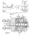
- FIG. 4 there is illustrated a sectional view of a multimanifold die device useful in forming the subject article, said device being generally designated by the reference numeral 20, the device 20 comprising a die body 21 having defined therein a centrally disposed aperture 22. Located within aperture 22 is a mandrel 40 equally spaced from the walls of the aperture 22 and secured to the device 20 by retaining member 41. Formed within the body 21 is first and second conduits 23 and 24 which carry melted thermoplastic and barrier materials P and B, respectively, into first and second plenums 25 and 26. Thermoplastic material P is divided into two streams that open into aperture 22, an inner stream 30 and an outer stream 31, said streams issuing from annular slots 28 and 27 that communicate with the plenum 25.
- a conduit 29 communicates with a third plenum 24 for directing a suitable adhesive or glue material G.
- the glue material G forms two streams, an inner stream 37 and an outer stream 38, said streams coming from glue slots 33 and 34.
- the barrier material B is carried within the die body 21 by plenum 26 which, in turn, communicates with the aperture 22 by means of barrier slot 39. It will be appreciated that a number of die configurations may be used to form the article herein, the aforementioned being just one embodiment.
- a tubular structure 10 being formed by passing molten thermoplastic materials from three separate conventional screw-type extruders 51, 52 and 53 which contain thermoplastic material, glue, and barrier material, respectively, to the multimanifold die device 20 where melted thermoplastic materials are united into the tubular body 10 as previously described and, thereafter, the molten materials are allowed to pass into a vacuum cooling and sizing chamber 54.
- thermally sensitive barrier or low gas permeable layer is situated in the multilayered structure proximate the outer surface as defined herein whereby it may be quenched or cooled quickly.
- this particular location of the barrier layer, that is proximate the outer surface also reduces the forces due to the differential shrinkage of the inner and outer layers and, therefore, further curtails the tendency of the gaseous inclusions to form. As a result, the formation of gaseous inclusions is substantially reduced in making such multilayered tubular bodies in accordance with this invention.
- the solidified tubular body After being cooled the solidified tubular body is pushed via belts 56 and 57 into cutting means 58 where it is severed into individual open end parison preforms designed A. Thereafter, the preform A is passed through an air oven 59 where it is heated to a predetermined orientation temperature and the preform is then transferred by means not shown to a thread-forming head 61 whereby the thread and finish configuration is readily formed.
- the parison A is grasped at the other end thereof by gripping fingers 62, which are brought together by means of cylinders or cams not shown, and relative movement effected between thread-forming head 61 and gripping fingers 62 by means of raising head 61 through the action of cylinder 63 to stretch the parison to the elongated condition depicted by reference character 60.
- preblow air is introduced through line 64 and mold halves 65 and 66 concurrently close on the thus-stretched parison 60.
- Sealing and severing inserts 55 in mold halves 65 and 66 allow the mechanical operation of bringing the parison walls into intimate contact and severing the parison. It will be appreciated that since the innermost portion of the multilayered structure is substantially one polymeric material, e.g., polypropylene, that this action brings together a larger area of common polymeric material which readily seals itself to form the bottom end wall.
- three separate extruders were used in a coextrusion line, the first (1) extruder hopper containing polypropylene copolymer having a density of about 0.90 and a crystalline melting point of about 165.56°C, the second (2) containing a copolymer of vinylidene chloride and vinyl chloride having a density of about 1.71 and a crystalline melting point of about 148.89°C; and the third (3) extruder containing a resinous, adhesive material comprising about 40 percent styrene and 60 percent butadiene.
- Each extruded tubular body thus formed had an outside diameter of about 31.75 mm and a wall thickness of about 5.842 mm.
- Each tubular body was cooled in a vacuum sizing and quenching chamber using a coolant at about 4.44°C, and thereafter cut into 254 mm lengths.
- a copolymer of vinylidene chloride (about 85 percent) and vinyl chloride (about 15 percent) were made.
- the barrier layer was bonded via the above-mentioned adhesive material to both an inner and an outer layer of polypropylene.
- the barrier material itself as well as the other materials were maintained substantially at the same quantitative level in each placement.
- the following table shows the distance the barrier was located from the outer surface and indicates the average number of inclusions per meter as well as the estimated average inclusion volume.
Landscapes
- Engineering & Computer Science (AREA)
- Mechanical Engineering (AREA)
- Manufacturing & Machinery (AREA)
- Laminated Bodies (AREA)
- Extrusion Moulding Of Plastics Or The Like (AREA)
Abstract
Description
- This invention relates to a nonflexible thick-walled tubular article capable of being biaxially oriented into a container possessing low gas permeability comprising at least three polymeric layers of which at least one is an intermediate polymeric layer being a barrier layer, this article being formed by simultaneously coextruding the polymeric layers together as a series of melted streams with the barrier layer being within the exterior one percent to 33 percent of the total thickness of the article and having an average thickness in the range of about 1 percent to about 20 percent of the total thickness of the article. Furthermore, the invention relates to a method for making such article which is suitable for producing containers and the like.
- The formation of multilayered structures is known wherein the separate layers contribute to the final properties. Many of these composite structures may be readily prepared by melting each individual component in separate zones and subsequently combining them in a predetermined configuration. In general, composite structures of two or more different polymeric materials may be readily coextruded to form a multilayered structure. In particular, a multilayered tubular structure may be readily made by conventional coextrusion processes wherein each thermoplastic material which is ultimately to formia layer in the composite is separately heated to its melt extrusion temperature by a conventional melt extruder and thereafter each melted material is forced by pressure feeding means into streams of melted thermoplastic material that enter a multimanifold die device provided with toroidal chambers and a common annular die orifice. The melted materials are fed into said device and form therein continuous annular layers as they exit the die orifice, each additional layer being fed to the device and issuing as annular coaxial layers that are essentially concentric with the initially formed annular layer. In effect the device provides an annular flow of plastic materials, one strata of thermoplastic material being circumferentially deposited upon the preceding one to produce the multilayered tubular body.
- In distributing thermoplastic materials into a multimanifold die device it has been found that several polymeric materials have the tendency to decompose or degrade when subjected to certain elevated temperatures, the elevated temperatures being reached oftentimes by heat from an adjacent coextruded material that must be processed at a higher melt extrusion temperature. Several polymers exhibit this tendency and, especially, prone are the so-called low gas permeable polymers. These rather susceptible polymeric materials when subjected to elevated temperature have the propensity to partially degrade or decompose whereby unwanted gaseous products or inclusions are formed that become entrapped and are embedded in the polymeric interlayers or matrix. These inclusions often serve as nuclei or sites of buildup for the ultimate deposition of various organic and inorganic substances in a finished article. In particular, this deposition is noticeable with tubular forms and, especially, when they are further processed via blow-molding to form necked containers.
- A number of patents disclose methods of making tubular, multilayered structures as well as methods of blow-molding certain thermoplastic structures. For example, a method of coextruding multilayered tubular bodies is described in US-A-3 308 508 as well as in US-A-3 354 506. Multilayered, flexible structures having at least one layer of low gas permeability are described in US-A-3 570 748 and US-A-3 956 544 as well as in US-A-4 139 665. Also rigid multilayered sheet structures are shown in US-A-3 645 838 and US-A-4 182 457. A useful process for blow-molding tubular bodies or parisons into high strength transparent hollow objects including containers is described in US Reissue
Patent 26 956. - A nonflexible thick-walled tubular article of the type mentioned in the beginning and a method for making such article is described in FR-A-1 436 158. However, there is no indication of the above problem of unwanted gaseous products or inclusions in this patent. The purpose why the barrier layer is arranged closer to the outside than to the inside of the tube according to FR-A-1 436 158 is to form first a base tube and then to complete this base tube by thin cover layers which are obviously added from outside because it is easier to do so than to add them from inside. This is a problem completely different from the above problem underlying the present invention.
- US-A-4 082 829 discloses a method for making a three-ply film containing a barrier layer as inner layer between two outer layers. In this method the film is produced in tubular form by making the first layer as an inflated tubing of greater wall thickness and cooling and quenching the same. Thereafter the other layers are coated one after the other on the first layer. It is clear that the purpose of making the first layer thicker than the second and third layers is to obtain a relatively stable tubing as base tubing for coating the same with the remaining layers similar as in FR-A-1 436 158.
- Furthermore, US-A-4 217 161 discloses a transparent multi-layer container comprising a co-extrudate of an oxygen-barrier resin layer and an orienting resin layer which is monoaxially or biaxially oriented, with an adhesive resin layer being preferably interposed between the oxygen-barrier layer and the orienting resin layer, and this co-extrudate is drawn and molded at a specific temperature determined relatively to the melting points and softening points of the respective resins. All parisons for making such containers disclosed in US-A-4 217 161 have a symmetric arrangement of layers with respect to the oxygen-barrier layer; that is, arrangements of layers in which the inner and outer layers are of equal thickness. However, the above-mentioned problem of unwanted gaseous products or inclusions is not indicated in this patent. The object underlying this patent is rather to attain a practically satisfactory interlaminar peel strength under falling, shaking or impact.
- The above problem of gas release caused by decomposition when extruding decomposable plastics materials such as vinylidene chloride is mentioned in US-A-3 321 803. However, the solution of this problem proposed in US-A-3 321 803 is to reduce the residence time of the plastic in the die to prevent undue heating of the plastic by use of a special extrusion die and thereby to inhibit the decomposition of the plastic material in the die.
- Thus, the particular problems resolved by the subject invention have not been appreciated or squarely addressed by the prior art.
- It was surprisingly found that the above problem of avoiding unwanted gaseous inclusions in a nonflexible thick-walled tubular article of the type mentioned in the beginning and in a method for making such tubular article is solved, according to the present invention, when the barrier layer is coextruded with at least one adjacent adhesive layer cojoined therewith to provide a marked decrease in relative volume of entrapped inclusions per given length.
- Therefore, where potentially degradable polymeric materials are incorporated as a layer or layers in tubular structures in accordance with this invention there is a marked improvement in properties advantageous to further fabrication including a substantial reduction in the tendency to form organic or inorganic inclusions. In essence, the multilayered tubular structure of the subject invention is novel and provides for unique properties and improvements not only in gas permeability but also in the mechanical properties of containers formed from said tubular structures including bottom wall sealability and neck configuration, which in turn, enables them to be useful for many purposes in the art, especially for parisons in blow-molding containers as hereinafter set forth.
- In this connection it should be mentioned that it has been found that in addition to the degradation or decomposition of these susceptible polymers there are apparently other phenomena at work that accentuate or cause a greater likelihood for this condition to exist, not only in frequency but in magnitude. Since there are a number of different polymeric materials that may be coextruded at the same time to form a given tubular body there is a marked tendency during any subsequent quenching or cooling for the various cojoined materials to contract or shrink at different levels resulting in stresses within the tubular structure. These stresses appear somehow to accelerate the formation of gaseous inclusions or bubbles that apparently display themselves. Seemingly, the differential contraction between the faster cooling outer layer where generally less shrinkage occurs and the slower cooling inner layer where generally more shrinkage occurs accelerates the buildup of these inclusions.
- According to the invention there is provided a tubular article and a method of making the same wherein the degradation of the barrier layer polymer material being highly susceptible to thermal degradation is substantially reduced.
- Furthermore, the invention provides a composite tubular article having excellent mechanical strength.
- Still, this invention provides a tubular article having at least one barrier layer that is substantially free of organic and/or inorganic inclusions.
- Yet the invention provides an improved tubular article for blow-molding into hollow objects, the objects having good sealability characteristics.
- Moreover, the invention minimizes or reduces the effect of differential shrinkage for a multilayered tubular article having a susceptible barrier layer.
- Additionally the invention provides a method for making a tubular article capable of allowing the manufacture of various types of containers having enhanced properties, including particularly low gas permeability, as well as containers having improved bottom wall sealability and neck-finish configuration.
- It is preferred that the barrier layer has an average thickness of from about 2 percent to about 12 percent of the total thickness of the article, particularly that the barrier layer has an average thickness of from about 3 percent to about 10 percent of the total thickness of the article.
- Other embodiments of the invention are stated in the dependent claims 2 to 4, 7, 9 to 11 and 14, 15.
- In one embodiment of the present invention, briefly summarized, there is provided a self-supporting, coextruded thermoplastic article comprising a plurality of layers of different polymeric materials bonded together, said article having at least one uncentered layer of low gas permeability situated proximate the surface of said article. The particular article herein contemplated includes a tubular parison structure whereby the uncentered layer of low gas permeability is the penultimate polymeric layer or one proximate the outer surface of said tubular parison structure. The article thickness being between about 2.54 to 12.7 mm with the barrier layer being between about 0.0254 to about 2.54 mm.
- The nature, principle, utility and further particularities of this invention will be apparent from the following detailed description including specific examples of practice illustrating preferred embodiments of the invention.
- In the drawings:
- Figure 1 is a perspective view of the tubular body of this invention;
- Figures 2 and 3 illustrate fragmentary cross sections of composite thermoplastic bodies of the subject invention;
- Figure 4 is a cross-sectional view of a multimanifold die assembly for making the article of this invention;
- Figure 5 is a view of a narrow neck container made from the tubular body of this invention; and
- Figure 6 depicts a schematic representation of the apparatus for forming containers like Figure 5 from tubular bodies of this invention.
- Turning first to Figures 1, 2 and 3 a sectional view of several rigid coextruded thermoplastic bodies are shown, each body itself being designated generally by
reference numeral 10. Thebody 10 comprises a first or outerpolymeric material 11 bonded by afirst glue layer 12 to a so-called unbalanced or uncenteredinner layer 13 which in turn is bonded to a second or innerpolymeric material 15 by asecond glue layer 14. As can be seen in Figure 3, the inner polymeric material may comprise different polymeric materials such as shown bylayers inner glue layers - In particular, the multilayered structure of the subject invention comprises a tubular thermoplastic body having a barrier layer sandwiched between other thermoplastic materials, with a glue or adhesive resin layer interposed between said thermoplastic layers, the barrier layer being proximate the exterior surface of said structure. When the barrier layer is so situated, it has been observed that there is less tendency for its decomposition or degradation and the formation of organic or inorganic inclusions which become oftentimes entrapped in the polymeric matrix during formation of a coextruded tubular structure. In the case of halogen-containing polymers the inclusions may often be hydrogen halides. Admittedly, when a tubular structure of polymeric material such as a single polymeric material or monolithic parison of polypropylene undergoes biaxial orientation during a stretch-and-blow operation the resulting article exhibits high strength as well as clarity. However, when such orientation is attempted with a multilayered tubular parison having a barrier layer or one of low gas permeability, it is found that the location of such a layer in a given multilayered parison in relation to the other layers becomes exceedingly critical in order to produce a container free or substantially free of imperfections or flaws due to such inclusions.
- In general, it has been found that the low gas permeable or barrier layer should be positioned away from the central plane of the sheet or tubular structure and is most preferably located towards the exterior portion, especially within the first one-third of layers of a given multilayered preform structure. In this regard the barrier layer is best located proximate the outer surface of the structure, being within about 1 percent to 33 percent of the total thickness and the barrier layer itself occupying from about 1 percent to 20 percent of said total thickness. In one embodiment the barrier layer may have a thickness substantially equal to the thickness of the first outer thermoplastic layer. In a most preferred embodiment the barrier layer should be situated within the outer 15±1 percent of the total thickness of the tubular body. Figures 2 and 3 show one position of the
barrier layer 13 and its relative thicknesses to the other layers within a given multilayered tubular body. - A wide range of thermoplastic materials, and preferably orientable materials, may be used for the polymeric layers, that is, for those polymeric layers other than the at least one barrier layer of low gas permeability. In particular, the thermoplastic materials include the solid olefins such as polyethylene, polypropylene and polybutylene. The polyolefins herein contemplated include polyethylene, polypropylene, resinous copolymers of ethylene and propylene and polymers of ethylene and/or propylene with minor proportions of olefinically unsaturated monomers such as the low molecular weight olefins having, for example, from 2 to 8 carbon atoms such as 1-butene, 1-pentene, 1-hexene, 1-heptene, and 1-octene. Other hydrocarbons useful for the copolymers herein are the copolymers of ethylene and propylene include divinylbenzene, allene, dimethallyl and isopentene. Also included in the thermoplastic materials for the layers that are not the barrier layer are polystyrene, polymethacrylates including polymethyl methacrylate and polybutyl methacrylate; polyvinyl alcohols; polyvinyl halides; polyvinyl acetals including polyvinyl trityral, polyallyl alcohol and polyallyl acetate; polyesters including polyethylene terephthalate and polycarbornates.
- The term low gas permeability layer or barrier layer as used herein include polyvinylidene chloride and its copolymers; polyacrylonitrite and its copolymers including poly(acrylonitrile-co-styrene-co-butadiene); polyamides such as nylon; and hydrolized polymers of vinyl acetate and ethylene, especially saponified copolymers thereof. In general, the term polyvinylidene chloride copolymers as used herein mean a polymeric material which contains at least 50 percent of vinylidene chloride. A preferred barrier layer in accordance with this invention is polyvinylidene chloride and its copolymers. Copolymerizable monomers with vinylidene chloride include vinyl chloride, butadiene, acrylonitrile, vinyl acetate, methyl acrylate, ethyl acrylate, butyl acrylate, and methyl methacrylate. Terpolymers can also be employed, e.g., a terpolymer of vinylidene chloride, methyl methacrylate and vinyl chloride.
- A relatively wide range of polymers and polymeric compositions are useful to increase the adhesion between the various thermoplastic layers as well as between the thermoplastic layers and the barrier layer. In making the tubular structures herein contemplated it is found most desirable to add adhesive or bonding layers between the barrier layer and the other thermoplastic layers. This has many advantages including the prevention of entrapping air in the coextruded material. In selecting adhering materials to serve as glue with respect to bonding polypropylene to vinylidene chloride polymers, a number of compositions may be used: compositions which are particularly advantageous are copolymers containing about 13 weight percent to about 35 weight percent vinyl acetate with from about 87 weight percent to about 65 weight percent ethylene, copolymer compositions of from about 20 to 30 weight percent ethyl acrylate with from about 80 to 70 weight percent ethylene, copolymer compositions from about 20 to 30 weight percent isobutyl acrylate with from about 80 to 70 weight percent of ethylene and chlorinated polyethylene containing from about 25 to 40 weight percent chlorine and copolymers of butadiene-styrene. Suitable polymers or polymeric compositions may be readily selected by determining the bonding strength of the particular layer combination, usually by using peel strength tests.
- In Figure 4 there is illustrated a sectional view of a multimanifold die device useful in forming the subject article, said device being generally designated by the
reference numeral 20, thedevice 20 comprising adie body 21 having defined therein a centrally disposedaperture 22. Located withinaperture 22 is amandrel 40 equally spaced from the walls of theaperture 22 and secured to thedevice 20 by retainingmember 41. Formed within thebody 21 is first andsecond conduits second plenums aperture 22, aninner stream 30 and anouter stream 31, said streams issuing fromannular slots plenum 25. A conduit 29 communicates with athird plenum 24 for directing a suitable adhesive or glue material G. From viewing Figure 4 it will be noted that the glue material G forms two streams, aninner stream 37 and anouter stream 38, said streams coming fromglue slots die body 21 by plenum 26 which, in turn, communicates with theaperture 22 by means ofbarrier slot 39. It will be appreciated that a number of die configurations may be used to form the article herein, the aforementioned being just one embodiment. - The formation of a biaxially oriented container shall now be described. With reference to Figure 6 there is shown a
tubular structure 10 being formed by passing molten thermoplastic materials from three separate conventional screw-type extruders device 20 where melted thermoplastic materials are united into thetubular body 10 as previously described and, thereafter, the molten materials are allowed to pass into a vacuum cooling and sizingchamber 54. It will be appreciated that some materials are required to be at an elevated melt temperature, such as for polypropylene, in comparison with another material such as a low gas permeable layer, and the time required to substantially cool the former material may not be ample whereby there results degradation or decomposition of the low gas permeable material. In the case of polyvinylidene chloride and its copolymers as a low gas permeable layer it is believed that inorganic materials such as hydrogen chloride may be formed as well as other organic ingredients. It follows from this invention that the thermally sensitive barrier or low gas permeable layer is situated in the multilayered structure proximate the outer surface as defined herein whereby it may be quenched or cooled quickly. Furthermore, this particular location of the barrier layer, that is proximate the outer surface, also reduces the forces due to the differential shrinkage of the inner and outer layers and, therefore, further curtails the tendency of the gaseous inclusions to form. As a result, the formation of gaseous inclusions is substantially reduced in making such multilayered tubular bodies in accordance with this invention. - After being cooled the solidified tubular body is pushed via
belts air oven 59 where it is heated to a predetermined orientation temperature and the preform is then transferred by means not shown to a thread-forminghead 61 whereby the thread and finish configuration is readily formed. The parison A is grasped at the other end thereof by grippingfingers 62, which are brought together by means of cylinders or cams not shown, and relative movement effected between thread-forminghead 61 andgripping fingers 62 by means of raisinghead 61 through the action ofcylinder 63 to stretch the parison to the elongated condition depicted byreference character 60. Thereafter, preblow air is introduced throughline 64 andmold halves parison 60. Sealing and severing inserts 55 inmold halves fingers 62 then retract to allow the severed tail portion T to fall free from the remainder of the parison. Thereafter, the main blow air is then introduced throughline 67. By this process the preform is biaxially stretched. A preferred method of closing and sealing a comparable parison, for instance, is shown and described in U.S. Patent No. 3,686,379 to Gilbert, the disclosure of which is hereby incorporated by reference. - The following example is presented in order to illustrate further the particular tubular structure and method to form the same in accordance with this invention.
- A series of coextruded tubular bodies, A through E, were made in which a layer having low gas permeability was positioned at various levels within the layered structure. In making these tubular bodies three separate extruders were used in a coextrusion line, the first (1) extruder hopper containing polypropylene copolymer having a density of about 0.90 and a crystalline melting point of about 165.56°C, the second (2) containing a copolymer of vinylidene chloride and vinyl chloride having a density of about 1.71 and a crystalline melting point of about 148.89°C; and the third (3) extruder containing a resinous, adhesive material comprising about 40 percent styrene and 60 percent butadiene. All three materials were melted and pumped by the extruders to a multimanifold die head wherein the three materials were coextruded to form continuous annular layers, each layer being fed to the die head and issuing as annular coaxial layers that were essentially concentric with the initially formed layer.
- Each extruded tubular body thus formed had an outside diameter of about 31.75 mm and a wall thickness of about 5.842 mm. Each tubular body was cooled in a vacuum sizing and quenching chamber using a coolant at about 4.44°C, and thereafter cut into 254 mm lengths. In order to demonstrate the criticality of the location of the barrier layer, viz., a copolymer of vinylidene chloride (about 85 percent) and vinyl chloride (about 15 percent), five different placements were made. The barrier layer was bonded via the above-mentioned adhesive material to both an inner and an outer layer of polypropylene. The barrier material itself as well as the other materials were maintained substantially at the same quantitative level in each placement. The following table shows the distance the barrier was located from the outer surface and indicates the average number of inclusions per meter as well as the estimated average inclusion volume. By multiplying the average number of inclusions per meter and estimated average inclusion volume and dividing by the inclusion volume per meter of Sample A the relative inclusion volume per meter is determined.

- It can be seen from the above table that when the barrier layer is proximate the outer surface, that is, if the barrier layer is within the outer about one-third of the total thickness, or more preferably within the outer about one-quarter of the total thickness of the tubular body there is a marked decrease in the relative inclusion volume per foot.
- As is apparent from the foregoing specification, the present invention is susceptible of being embodied with various alterations and modifications which may differ particularly from those that have been described in the preceding specification and description. For this reason, it is to be fully understood that all of the foregoing is intended to be merely illustrative and is not to be construed or interpreted as being restrictive or otherwise limiting of the present invention as claimed.
Claims (15)
Priority Applications (1)
| Application Number | Priority Date | Filing Date | Title |
|---|---|---|---|
| AT82106584T ATE29237T1 (en) | 1981-10-05 | 1982-07-21 | MULTI-LAYER PIPE BODY WITH AN OFF-CENTRE BARRIER LAYER. |
Applications Claiming Priority (2)
| Application Number | Priority Date | Filing Date | Title |
|---|---|---|---|
| US30829281A | 1981-10-05 | 1981-10-05 | |
| US308292 | 1989-02-09 |
Publications (3)
| Publication Number | Publication Date |
|---|---|
| EP0076366A2 EP0076366A2 (en) | 1983-04-13 |
| EP0076366A3 EP0076366A3 (en) | 1984-11-14 |
| EP0076366B1 true EP0076366B1 (en) | 1987-09-02 |
Family
ID=23193373
Family Applications (1)
| Application Number | Title | Priority Date | Filing Date |
|---|---|---|---|
| EP82106584A Expired EP0076366B1 (en) | 1981-10-05 | 1982-07-21 | Multilayer tubular body with uncentered barrier layer |
Country Status (4)
| Country | Link |
|---|---|
| EP (1) | EP0076366B1 (en) |
| JP (1) | JPS5871130A (en) |
| AT (1) | ATE29237T1 (en) |
| DE (1) | DE3277113D1 (en) |
Families Citing this family (18)
| Publication number | Priority date | Publication date | Assignee | Title |
|---|---|---|---|---|
| SE468381B (en) * | 1983-04-28 | 1993-01-11 | Toyo Seikan Kaisha Ltd | MULTI-LAYER STRAIGHT POLYESTER BOTTLE AND PROCEDURES FOR PRODUCING THEREOF |
| US4649004A (en) * | 1983-12-27 | 1987-03-10 | Toyo Seikan Kaisha, Ltd. | Process for production of multi-layer pipes for draw-forming |
| US4550043A (en) * | 1984-02-17 | 1985-10-29 | Continental Plastic Containers, Inc. | Preform with internal barrier and internal layer of high thermal stability and products made from the same |
| US4609516A (en) * | 1984-02-17 | 1986-09-02 | Continental Pet Technologies, Inc. | Method of forming laminated preforms |
| JPS61235126A (en) * | 1985-04-12 | 1986-10-20 | Nissei Ee S B Kikai Kk | Multi-layer vessel and manufacture thereof |
| US4992335A (en) * | 1985-09-12 | 1991-02-12 | Sanders Associates, Inc. | Composite material and method of making same |
| US4935308A (en) * | 1985-09-12 | 1990-06-19 | Sanders Associates | Composite material and method of making same |
| US5019453A (en) * | 1985-09-12 | 1991-05-28 | Guerra Richard J | Composite material and method of making same |
| DE3601345A1 (en) * | 1986-01-18 | 1987-07-23 | Reifenhaeuser Masch | EXTRACTION TOOL FOR THE PRODUCTION OF A MULTILAYER TUBULAR FILM |
| EP0279321A3 (en) * | 1987-02-14 | 1990-05-09 | BEKUM Maschinenfabriken GmbH | Co-extrusion head |
| FR2611581B1 (en) * | 1987-02-20 | 1989-06-23 | Flexopack Sarl | METHOD FOR MANUFACTURING OTHERS IN SYNTHETIC MATERIAL, DEVICE FOR CARRYING OUT SAID METHOD, AND THUS OBTAINED |
| DE3720560C1 (en) * | 1987-06-22 | 1988-09-15 | Bekum Maschf Gmbh | Coextrusion head |
| US4944972A (en) * | 1987-12-31 | 1990-07-31 | American National Can Company | Coextrusion apparatus, methods, and related films and packages |
| GB2222355A (en) * | 1988-08-26 | 1990-02-28 | Courtaulds Films & Packaging | Microwavable food container |
| DE3902270A1 (en) * | 1989-01-26 | 1990-08-02 | Guenter Dipl Ing Richter | METHOD AND DEVICE FOR THE DISCONTINUOUS PRODUCTION OF MULTILAYERED, COEXTRUDED, TUBULAR PREFORMINGS FROM THERMOPLASTIC PLASTIC |
| DE3910103A1 (en) * | 1989-03-29 | 1990-10-11 | Wolff Walsrode Ag | METAL LAYER-FREE COMPOSITE FILMS |
| DE4337491A1 (en) * | 1993-11-03 | 1995-05-04 | Kautex Werke Gmbh | Container manufactured using the co-extrusion blow molding process |
| DE10314779A1 (en) * | 2003-03-31 | 2004-10-14 | Kuraray Specialities Europe Gmbh | Medical-pharmaceutical plastic container with improved barrier effect |
Family Cites Families (7)
| Publication number | Priority date | Publication date | Assignee | Title |
|---|---|---|---|---|
| GB937456A (en) * | 1958-12-08 | 1963-09-18 | Gen Mills Inc | Improvements in or relating to photosensors |
| FR1436158A (en) * | 1964-04-01 | 1966-04-22 | Continental Can Co | Method and apparatus for manufacturing coated containers |
| US3321803A (en) * | 1966-01-14 | 1967-05-30 | Nat Distillers Chem Corp | Extrusion die for easily decomposable materials |
| US3640659A (en) * | 1968-08-01 | 1972-02-08 | Bristol Myers Co | Split die for extruding laminated tubing |
| US4082829A (en) * | 1971-03-30 | 1978-04-04 | W. R. Grace & Co. | Process for melt extruding coating grade saran |
| US4109037A (en) * | 1973-04-30 | 1978-08-22 | Toyo Seikan Kaisha, Ltd. | Laminated packing materials |
| US4217161A (en) * | 1976-08-10 | 1980-08-12 | Toyo Seikan Kaisha Limited | Process for making a container |
-
1982
- 1982-07-21 AT AT82106584T patent/ATE29237T1/en not_active IP Right Cessation
- 1982-07-21 DE DE8282106584T patent/DE3277113D1/en not_active Expired
- 1982-07-21 EP EP82106584A patent/EP0076366B1/en not_active Expired
- 1982-10-05 JP JP57174090A patent/JPS5871130A/en active Pending
Also Published As
| Publication number | Publication date |
|---|---|
| ATE29237T1 (en) | 1987-09-15 |
| DE3277113D1 (en) | 1987-10-08 |
| EP0076366A2 (en) | 1983-04-13 |
| EP0076366A3 (en) | 1984-11-14 |
| JPS5871130A (en) | 1983-04-27 |
Similar Documents
| Publication | Publication Date | Title |
|---|---|---|
| US4436778A (en) | Multilayer tubular body with uncentered barrier layer | |
| EP0076366B1 (en) | Multilayer tubular body with uncentered barrier layer | |
| US4522775A (en) | Apparatus and method for producing multilayered laminates | |
| US4064296A (en) | Heat shrinkable multi-layer film of hydrolyzed ethylene vinyl acetate and a cross-linked olefin polymer | |
| US4244914A (en) | Process for preparing gas-, vapor- and odor-proof coupled and coextruded multilayer articles of thermoplastic material and closed-surface bodies comprising the same | |
| KR960008301B1 (en) | Biaxially oriented multilayer barrier films | |
| US3821182A (en) | Method for preparing of film of a vinylidene chloride polymer | |
| US3940001A (en) | Recyclable plastic containers | |
| US4112181A (en) | Method for preparing a film of vinylidene chloride polymer | |
| US6218024B1 (en) | Multilayer plastic film | |
| US9481143B2 (en) | Multilayer structures having annular profiles | |
| US4048428A (en) | Method for preparing a film of vinylidene chloride polymer | |
| US4824618A (en) | Coextrusion blowmolding process | |
| GB2153739A (en) | Process for production of multi-layer polyethylene terephthalate pipes for (stretch) blow moulding | |
| US4153206A (en) | Crushing process for recyclable plastic containers | |
| AU740936B2 (en) | Biaxially oriented fluoropolymer films | |
| US4357191A (en) | Laminar thermoplastic film constructions | |
| US5788926A (en) | Plastic bottle and process for making the same | |
| SE468381B (en) | MULTI-LAYER STRAIGHT POLYESTER BOTTLE AND PROCEDURES FOR PRODUCING THEREOF | |
| JP2588484B2 (en) | Method for producing film from semi-crystalline molten polymer by coextrusion blow molding of tube | |
| EP0287246B1 (en) | Method of manufacturing polybutylene terephthalate resin films | |
| JPS6159896B2 (en) | ||
| CN1693153B (en) | Multi-layer polymer composite packaging container with nano-layer texture and processing method thereof | |
| EP4342654B1 (en) | Crystal clear high barrier thermoformed plastic bottle | |
| JPS6320691B2 (en) |
Legal Events
| Date | Code | Title | Description |
|---|---|---|---|
| PUAI | Public reference made under article 153(3) epc to a published international application that has entered the european phase |
Free format text: ORIGINAL CODE: 0009012 |
|
| AK | Designated contracting states |
Designated state(s): AT BE CH DE FR GB IT LI LU NL SE |
|
| PUAL | Search report despatched |
Free format text: ORIGINAL CODE: 0009013 |
|
| AK | Designated contracting states |
Designated state(s): AT BE CH DE FR GB IT LI LU NL SE |
|
| 17P | Request for examination filed |
Effective date: 19850116 |
|
| BERE | Be: lapsed |
Owner name: BALL CORP. Effective date: 19850731 |
|
| GRAA | (expected) grant |
Free format text: ORIGINAL CODE: 0009210 |
|
| AK | Designated contracting states |
Kind code of ref document: B1 Designated state(s): AT BE CH DE FR GB IT LI LU NL SE |
|
| REF | Corresponds to: |
Ref document number: 29237 Country of ref document: AT Date of ref document: 19870915 Kind code of ref document: T |
|
| REF | Corresponds to: |
Ref document number: 3277113 Country of ref document: DE Date of ref document: 19871008 |
|
| ITF | It: translation for a ep patent filed | ||
| ET | Fr: translation filed | ||
| PLBI | Opposition filed |
Free format text: ORIGINAL CODE: 0009260 |
|
| 26 | Opposition filed |
Opponent name: SOLVAY & CIE, S.A., BRUXELLES Effective date: 19880502 |
|
| PLBI | Opposition filed |
Free format text: ORIGINAL CODE: 0009260 |
|
| PG25 | Lapsed in a contracting state [announced via postgrant information from national office to epo] |
Ref country code: GB Effective date: 19880721 Ref country code: AT Effective date: 19880721 |
|
| PG25 | Lapsed in a contracting state [announced via postgrant information from national office to epo] |
Ref country code: SE Effective date: 19880722 |
|
| PG25 | Lapsed in a contracting state [announced via postgrant information from national office to epo] |
Ref country code: LU Free format text: LAPSE BECAUSE OF NON-PAYMENT OF DUE FEES Effective date: 19880731 Ref country code: BE Effective date: 19880731 |
|
| NLR1 | Nl: opposition has been filed with the epo |
Opponent name: SOLVAY & CIE, S.A. |
|
| PLAB | Opposition data, opponent's data or that of the opponent's representative modified |
Free format text: ORIGINAL CODE: 0009299OPPO |
|
| 26 | Opposition filed |
Opponent name: HOECHST AKTIENGESELLSCHAFT,FRANKFURT(MAIN) Effective date: 19880527 Opponent name: SOLVAY & CIE, S.A., BRUXELLES Effective date: 19880502 |
|
| R26 | Opposition filed (corrected) |
Opponent name: SOLVAY & CIE, S.A., BRUXELLES * 880817 HOECHST AKT Effective date: 19880502 |
|
| NLR1 | Nl: opposition has been filed with the epo |
Opponent name: HOECHST AKTIENGESELLSCHAFT |
|
| BERE | Be: lapsed |
Owner name: BALL CORP. Effective date: 19880731 |
|
| PG25 | Lapsed in a contracting state [announced via postgrant information from national office to epo] |
Ref country code: NL Effective date: 19890201 |
|
| NLV4 | Nl: lapsed or anulled due to non-payment of the annual fee | ||
| GBPC | Gb: european patent ceased through non-payment of renewal fee | ||
| PG25 | Lapsed in a contracting state [announced via postgrant information from national office to epo] |
Ref country code: FR Free format text: LAPSE BECAUSE OF NON-PAYMENT OF DUE FEES Effective date: 19890331 |
|
| REG | Reference to a national code |
Ref country code: CH Ref legal event code: PL |
|
| PG25 | Lapsed in a contracting state [announced via postgrant information from national office to epo] |
Ref country code: DE Effective date: 19890401 |
|
| REG | Reference to a national code |
Ref country code: FR Ref legal event code: ST |
|
| RDAG | Patent revoked |
Free format text: ORIGINAL CODE: 0009271 |
|
| STAA | Information on the status of an ep patent application or granted ep patent |
Free format text: STATUS: PATENT REVOKED |
|
| 27W | Patent revoked |
Effective date: 19890720 |
|
| GBPR | Gb: patent revoked under art. 102 of the ep convention designating the uk as contracting state | ||
| EUG | Se: european patent has lapsed |
Ref document number: 82106584.4 Effective date: 19890510 |