EP0076204B1 - Dispositif de protection neutronique supérieure pour assemblage de réacteur nucléaire - Google Patents
Dispositif de protection neutronique supérieure pour assemblage de réacteur nucléaire Download PDFInfo
- Publication number
- EP0076204B1 EP0076204B1 EP82401717A EP82401717A EP0076204B1 EP 0076204 B1 EP0076204 B1 EP 0076204B1 EP 82401717 A EP82401717 A EP 82401717A EP 82401717 A EP82401717 A EP 82401717A EP 0076204 B1 EP0076204 B1 EP 0076204B1
- Authority
- EP
- European Patent Office
- Prior art keywords
- wall
- nuclear reactor
- assembly according
- reactor assembly
- bracing
- Prior art date
- Legal status (The legal status is an assumption and is not a legal conclusion. Google has not performed a legal analysis and makes no representation as to the accuracy of the status listed.)
- Expired
Links
- 239000003758 nuclear fuel Substances 0.000 title 1
- 238000003466 welding Methods 0.000 claims description 4
- 239000011358 absorbing material Substances 0.000 claims 3
- 125000006850 spacer group Chemical group 0.000 description 31
- DGAQECJNVWCQMB-PUAWFVPOSA-M Ilexoside XXIX Chemical group C[C@@H]1CC[C@@]2(CC[C@@]3(C(=CC[C@H]4[C@]3(CC[C@@H]5[C@@]4(CC[C@@H](C5(C)C)OS(=O)(=O)[O-])C)C)[C@@H]2[C@]1(C)O)C)C(=O)O[C@H]6[C@@H]([C@H]([C@@H]([C@H](O6)CO)O)O)O.[Na+] DGAQECJNVWCQMB-PUAWFVPOSA-M 0.000 description 9
- 229910052708 sodium Inorganic materials 0.000 description 9
- 239000011734 sodium Substances 0.000 description 9
- 229910052580 B4C Inorganic materials 0.000 description 6
- 230000000712 assembly Effects 0.000 description 6
- 238000000429 assembly Methods 0.000 description 6
- INAHAJYZKVIDIZ-UHFFFAOYSA-N boron carbide Chemical compound B12B3B4C32B41 INAHAJYZKVIDIZ-UHFFFAOYSA-N 0.000 description 6
- 239000007788 liquid Substances 0.000 description 6
- 238000000034 method Methods 0.000 description 6
- 229910001220 stainless steel Inorganic materials 0.000 description 3
- 239000010935 stainless steel Substances 0.000 description 3
- 238000004519 manufacturing process Methods 0.000 description 2
- 229910000831 Steel Inorganic materials 0.000 description 1
- 240000008042 Zea mays Species 0.000 description 1
- 230000002745 absorbent Effects 0.000 description 1
- 239000002250 absorbent Substances 0.000 description 1
- 230000004913 activation Effects 0.000 description 1
- 230000000903 blocking effect Effects 0.000 description 1
- 239000000470 constituent Substances 0.000 description 1
- 239000012809 cooling fluid Substances 0.000 description 1
- 230000009849 deactivation Effects 0.000 description 1
- 230000000694 effects Effects 0.000 description 1
- 239000000446 fuel Substances 0.000 description 1
- 229910052734 helium Inorganic materials 0.000 description 1
- 239000001307 helium Substances 0.000 description 1
- SWQJXJOGLNCZEY-UHFFFAOYSA-N helium atom Chemical compound [He] SWQJXJOGLNCZEY-UHFFFAOYSA-N 0.000 description 1
- 238000009434 installation Methods 0.000 description 1
- 238000012423 maintenance Methods 0.000 description 1
- 239000000463 material Substances 0.000 description 1
- 230000001869 rapid Effects 0.000 description 1
- 238000012958 reprocessing Methods 0.000 description 1
- 239000010959 steel Substances 0.000 description 1
- 238000003860 storage Methods 0.000 description 1
- 230000008961 swelling Effects 0.000 description 1
Images
Classifications
-
- G—PHYSICS
- G21—NUCLEAR PHYSICS; NUCLEAR ENGINEERING
- G21C—NUCLEAR REACTORS
- G21C3/00—Reactor fuel elements and their assemblies; Selection of substances for use as reactor fuel elements
- G21C3/30—Assemblies of a number of fuel elements in the form of a rigid unit
- G21C3/32—Bundles of parallel pin-, rod-, or tube-shaped fuel elements
- G21C3/326—Bundles of parallel pin-, rod-, or tube-shaped fuel elements comprising fuel elements of different composition; comprising, in addition to the fuel elements, other pin-, rod-, or tube-shaped elements, e.g. control rods, grid support rods, fertile rods, poison rods or dummy rods
-
- G—PHYSICS
- G21—NUCLEAR PHYSICS; NUCLEAR ENGINEERING
- G21C—NUCLEAR REACTORS
- G21C11/00—Shielding structurally associated with the reactor
- G21C11/02—Biological shielding ; Neutron or gamma shielding
- G21C11/022—Biological shielding ; Neutron or gamma shielding inside the reactor vessel
- G21C11/024—Biological shielding ; Neutron or gamma shielding inside the reactor vessel structurally combined with the casing
-
- Y—GENERAL TAGGING OF NEW TECHNOLOGICAL DEVELOPMENTS; GENERAL TAGGING OF CROSS-SECTIONAL TECHNOLOGIES SPANNING OVER SEVERAL SECTIONS OF THE IPC; TECHNICAL SUBJECTS COVERED BY FORMER USPC CROSS-REFERENCE ART COLLECTIONS [XRACs] AND DIGESTS
- Y02—TECHNOLOGIES OR APPLICATIONS FOR MITIGATION OR ADAPTATION AGAINST CLIMATE CHANGE
- Y02E—REDUCTION OF GREENHOUSE GAS [GHG] EMISSIONS, RELATED TO ENERGY GENERATION, TRANSMISSION OR DISTRIBUTION
- Y02E30/00—Energy generation of nuclear origin
- Y02E30/30—Nuclear fission reactors
Definitions
- the subject of the present invention is an assembly of a nuclear reactor and more particularly of fast neutron reactors.
- the protection is supplemented by so-called "upper neutron protection sleeves" placed at the upper part of the assemblies.
- each assembly comprises, at the top, a sleeve-shaped head and, at the bottom, a foot, arranged on either side of the assembly body.
- the sleeve has a greater thickness than that of the assembly body and the space provided in its central part allows the circulation of the cooling fluid, for example liquid sodium, from bottom to top through the assembly.
- the cooling fluid for example liquid sodium
- the subject of the present invention is precisely a nuclear reactor assembly comprising a device which overcomes these drawbacks by being simple to produce and easily removable during the dismantling of the irradiated assembly.
- the neutron protection device located inside a wall placed at the upper part of the assembly body comprises a container at least partially filled with a neutron absorbing product, maintained using at least one spacer plate, the assembly consisting of the container and the spacer plates being located inside said wall.
- each of the aforementioned spacer plates comprises an outer edge of which at least one part is substantially straight and an inner edge of which at least one part conforms to the shape of said container.
- male spacer plates Two types are used in the device according to the invention: some, known as “male spacer plates, are characterized in that their upper part exceeds the top of the assembly body, has an outer edge inclined up and down towards the outside of the wall surrounding the device and has a notch opening towards the outside of said wall and allowing the attachment of a handling device.
- the others, called “female spacer plates” are flush with the top of the assembly body and have at least a portion of the upper part of their inner edge inclined up and down towards the inside of the space delimited by the mentioned wall. above and, still in the upper part of their inner edge, a notch opening towards the interior of said space and also allowing the attachment of a handling device.
- the device comprises several containers at least partially filled with a neutron absorbing product, each of the containers being held by a single spacer plate.
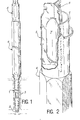
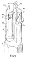
- Figure 1 shows an assembly for fast neutron reactor which consists essentially of three parts: the foot 1 whose lower end 2 has a conical shape so that it can be positioned in the bottom of the reactor vessel. We also see openings 3 through which the liquid sodium enters, which then flows from bottom to top through the assembly.
- the body 4 thereof, containing the fissile or fertile needles, is surmounted by the neutron protection device 5 according to the invention.
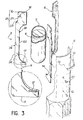
- FIG. 2 the upper part of the assembly body 4 is formed of a wall 6 of cylindrical shape. Inside this is a container 7 containing a product 8 capable of absorbing neutrons, for example boron carbide, and maintained inside the wall 6 by 3 spacer plates 9 which, in the 'example of Figure 2, are male spacer plates.
- a product 8 capable of absorbing neutrons, for example boron carbide
- the container 7 is held by three spacer plates 9. These these, which can advantageously be made of stainless steel, can be obtained in a simple manner, for example by stamping of laminated sheets, by microfusion or by hot stamping in particular.
- each plate 9 includes an inner edge 20, a part 22 of which consists of a rectilinear portion terminated by two portions in a quarter of a circle in order to conform to the shape of the container 7, which is a cylinder terminated by two half-spheres.
- the assembly thus formed is then introduced inside the wall 6 and the spacers 9 are fixed to the latter.
- This operation can be done in several ways: one can for example make a fixing by nailing using special nails 12 introduced into holes 13 in the wall 6 and holes 14 previously drilled on the edge of each spacer in the part straight from the outer edge, the head of each nail can be welded to the wall 6. It is also possible to use profiled corners 30 which are embedded in the spacer plates 9 and held by welding on the wall 6.
- a third method consists in deforming locally the wall 6 so as to create bumps which penetrate into notches previously formed on the edge of the spacer plates 9.
- this fixing can be achieved by strapping using one or more flanges 15 surrounding the wall 6 and held thereon by welding.
- the spacers 9 may be provided with an anti-vibration system which is in the form of slots 17 made in the upper part and / or in the lower part thereof. Such a slot is shown in the enlarged detail of FIG. 3.
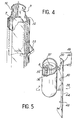
- FIG. 4 shows the device placed inside a wall 32 of hexagonal shape and held by strapping using a hexagonal flange 33.
- the upper part of those -this exceeds the upper edge of the wall 6.
- This arrangement has a double advantage: firstly, it allows the attachment of the device by a handling device thanks to the notches 16. In addition, it prevents the foot of a another assembly to penetrate inside the neutron protection device: if such an incident occurs, there is a risk of blocking the passage of liquid sodium at the top of the assembly. Thanks to the invention, this risk is eliminated: the foot of the second assembly is deflected by the plates 9 and the sodium can flow through at least one of the spaces delimited by the wall 32 and the plates 9. Thus, even in the event of accidental stopping of the circulation pumps, the heat can be evacuated by the movements of natural convection inside the sodium mass.
- FIG. 5 illustrates the preferred embodiment of the container 7 used in the invention and containing the product capable of absorbing neutrons.
- the container 7 essentially consists of an external envelope 34 made of stainless steel sheet, in the form of a cylinder, the ends of which, which may be conical or hemispherical, are closed. Inside this external envelope is disposed an internal envelope 36, also made of stainless steel sheet, but of small thickness, incompletely filled with boron carbide. Finally, at the center of the internal envelope, and substantially along its axis, there is a tube 37 which can deform under the effect of the swelling of boron carbide and whose the interior constitutes a free volume to contain the helium released by the boron carbide during the irradiation.
- FIG. 5 also shows a female spacer plate 39 used in the device according to the invention.
- a straight outer edge 44 provided with notches 45 making it possible to fix the plate 39 on a wall such as the walls 6 or 32 and an inner edge 40 of which a part 42 follows the shape of the container 7.
- the upper part 48 of the inner edge 40 which has a portion 50 inclined up and down towards the inside of the device and followed by a vertical part 47 in which is provided a notch 46 allowing the attachment of the device by means of a handling device.
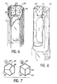
- FIG. 6 shows a device fitted with female plates 39 placed inside a wall 52 of hexagonal shape. It can be seen on examining this figure that, when female plates are used, the upper part thereof is flush with the upper edge of the wall 52.
- This arrangement also allows the attachment of the device by means of a handling device and, in the event of a false operation, the foot of another assembly penetrates only partially inside the wall 52: the liquid sodium can therefore s flow into the spaces delimited by the container 7, the plates 39 and the wall 52. Holes 53 formed in the upper part of the wall 52 can improve the evacuation of the liquid sodium.
- Figures 7a and 7b illustrate the two ways of arranging the spacers to fix them on a hexagonal wall: one can for example fix the plate 39 in the middle of the face 56 of the wall 52 ( Figure 7a) or at the junction between the faces 56 and 57 of said wall (FIG. 7b).
- Figure 8 shows a device similar to that of Figure 6 placed in a cylindrical wall 62. As female plates 39 are still used, the upper part of these does not exceed the upper edge of the wall 62 which, like the wall 52 of FIG. 6, can be pierced with a number of holes 63 for the passage of liquid sodium.
- Figure 9 illustrates a variant in which the device comprises several containers containing a neutron absorbing product.
- the cylindrical envelope 6 fixed to the upper part of the assembly 4 and inside which there are three spacer plates 9a, 9b and 9c.
- This is constituted in the same way as the container 7 of FIG. 5 with the deformable tube 37 placed at the center of the mass 8 of neutron absorbing product.
- the superior neutron protection device according to the invention has a certain number of advantageous advantages and first of all a simple manufacturing, and all the more economical as the gain in weight and in dimension is important compared to the devices of the prior art using thick steel sleeves.
- the assembly and disassembly are very easy, which simplifies maintenance operations, especially when dismantling irradiated assemblies.
- the storage volumes, either during the manufacture of the assemblies, or during their dismantling are very reduced and, depending on the case, either the complete device or the container 7 or the boron carbide alone can be recovered for reuse after deactivation.
- the container 7 may contain boron carbide or any other product having good absorbent properties vis-à-vis the neutrons.
Landscapes
- Engineering & Computer Science (AREA)
- Physics & Mathematics (AREA)
- Plasma & Fusion (AREA)
- General Engineering & Computer Science (AREA)
- High Energy & Nuclear Physics (AREA)
- Life Sciences & Earth Sciences (AREA)
- Health & Medical Sciences (AREA)
- Biomedical Technology (AREA)
- General Health & Medical Sciences (AREA)
- Molecular Biology (AREA)
- Monitoring And Testing Of Nuclear Reactors (AREA)
- Structure Of Emergency Protection For Nuclear Reactors (AREA)
- Measurement Of Radiation (AREA)
- Emergency Protection Circuit Devices (AREA)
- Particle Accelerators (AREA)
Applications Claiming Priority (2)
| Application Number | Priority Date | Filing Date | Title |
|---|---|---|---|
| FR8118413 | 1981-09-30 | ||
| FR8118413A FR2513797A1 (fr) | 1981-09-30 | 1981-09-30 | Dispositif de protection neutronique superieure pour assemblage de reacteur nucleaire |
Publications (2)
| Publication Number | Publication Date |
|---|---|
| EP0076204A1 EP0076204A1 (fr) | 1983-04-06 |
| EP0076204B1 true EP0076204B1 (fr) | 1986-01-02 |
Family
ID=9262612
Family Applications (1)
| Application Number | Title | Priority Date | Filing Date |
|---|---|---|---|
| EP82401717A Expired EP0076204B1 (fr) | 1981-09-30 | 1982-09-22 | Dispositif de protection neutronique supérieure pour assemblage de réacteur nucléaire |
Country Status (5)
| Country | Link |
|---|---|
| US (1) | US4493813A (cg-RX-API-DMAC7.html) |
| EP (1) | EP0076204B1 (cg-RX-API-DMAC7.html) |
| JP (1) | JPS5868694A (cg-RX-API-DMAC7.html) |
| DE (1) | DE3268310D1 (cg-RX-API-DMAC7.html) |
| FR (1) | FR2513797A1 (cg-RX-API-DMAC7.html) |
Families Citing this family (35)
| Publication number | Priority date | Publication date | Assignee | Title |
|---|---|---|---|---|
| GB8321491D0 (en) * | 1983-08-10 | 1983-09-14 | Atomic Energy Authority Uk | Nuclear fuel element |
| US4698510A (en) * | 1986-01-29 | 1987-10-06 | Halliburton Company | Multiple reservoir transportation assembly for radioactive substances, and related method |
| US4786805A (en) * | 1986-10-16 | 1988-11-22 | Halliburton Company | Reusable radioactive material shipping container including cartridge and injector |
| DE3875542T2 (de) * | 1987-07-22 | 1993-03-18 | British Nuclear Fuels Plc | Kernreaktorspaltzonen-teileinheit. |
| GB2221079A (en) * | 1988-07-19 | 1990-01-24 | Atomic Energy Authority Uk | A method and apparatus for inhibiting thermal cycling |
| US20040105520A1 (en) * | 2002-07-08 | 2004-06-03 | Carter Gary Shelton | Method and apparatus for the ex-core production of nuclear isotopes in commercial PWRs |
| US8953731B2 (en) * | 2004-12-03 | 2015-02-10 | General Electric Company | Method of producing isotopes in power nuclear reactors |
| US7526058B2 (en) * | 2004-12-03 | 2009-04-28 | General Electric Company | Rod assembly for nuclear reactors |
| US8842800B2 (en) * | 2007-11-28 | 2014-09-23 | Ge-Hitachi Nuclear Energy Americas Llc | Fuel rod designs using internal spacer element and methods of using the same |
| US9362009B2 (en) * | 2007-11-28 | 2016-06-07 | Ge-Hitachi Nuclear Energy Americas Llc | Cross-section reducing isotope system |
| US20090135989A1 (en) * | 2007-11-28 | 2009-05-28 | Ge-Hitachi Nuclear Energy Americas Llc | Segmented fuel rod bundle designs using fixed spacer plates |
| US9202598B2 (en) | 2007-11-28 | 2015-12-01 | Ge-Hitachi Nuclear Energy Americas Llc | Fail-free fuel bundle assembly |
| US20090135990A1 (en) * | 2007-11-28 | 2009-05-28 | Ge-Hitachi Nuclear Energy Americas Llc | Placement of target rods in BWR bundle |
| US8437443B2 (en) | 2008-02-21 | 2013-05-07 | Ge-Hitachi Nuclear Energy Americas Llc | Apparatuses and methods for production of radioisotopes in nuclear reactor instrumentation tubes |
| US8712000B2 (en) * | 2007-12-13 | 2014-04-29 | Global Nuclear Fuel—Americas, LLC | Tranverse in-core probe monitoring and calibration device for nuclear power plants, and method thereof |
| US8885791B2 (en) * | 2007-12-18 | 2014-11-11 | Ge-Hitachi Nuclear Energy Americas Llc | Fuel rods having irradiation target end pieces |
| US8180014B2 (en) * | 2007-12-20 | 2012-05-15 | Global Nuclear Fuel-Americas, Llc | Tiered tie plates and fuel bundles using the same |
| US7970095B2 (en) * | 2008-04-03 | 2011-06-28 | GE - Hitachi Nuclear Energy Americas LLC | Radioisotope production structures, fuel assemblies having the same, and methods of using the same |
| US8681924B2 (en) | 2008-04-29 | 2014-03-25 | Holtec International | Single-plate neutron absorbing apparatus and method of manufacturing the same |
| US11569001B2 (en) | 2008-04-29 | 2023-01-31 | Holtec International | Autonomous self-powered system for removing thermal energy from pools of liquid heated by radioactive materials |
| US8050377B2 (en) | 2008-05-01 | 2011-11-01 | Ge-Hitachi Nuclear Energy Americas Llc | Irradiation target retention systems, fuel assemblies having the same, and methods of using the same |
| US8270555B2 (en) * | 2008-05-01 | 2012-09-18 | Ge-Hitachi Nuclear Energy Americas Llc | Systems and methods for storage and processing of radioisotopes |
| US7781637B2 (en) * | 2008-07-30 | 2010-08-24 | Ge-Hitachi Nuclear Energy Americas Llc | Segmented waste rods for handling nuclear waste and methods of using and fabricating the same |
| US8699651B2 (en) | 2009-04-15 | 2014-04-15 | Ge-Hitachi Nuclear Energy Americas Llc | Method and system for simultaneous irradiation and elution capsule |
| US9165691B2 (en) * | 2009-04-17 | 2015-10-20 | Ge-Hitachi Nuclear Energy Americas Llc | Burnable poison materials and apparatuses for nuclear reactors and methods of using the same |
| US8366088B2 (en) * | 2009-07-10 | 2013-02-05 | Ge-Hitachi Nuclear Energy Americas Llc | Brachytherapy and radiography target holding device |
| US9431138B2 (en) * | 2009-07-10 | 2016-08-30 | Ge-Hitachi Nuclear Energy Americas, Llc | Method of generating specified activities within a target holding device |
| US8638899B2 (en) * | 2009-07-15 | 2014-01-28 | Ge-Hitachi Nuclear Energy Americas Llc | Methods and apparatuses for producing isotopes in nuclear fuel assembly water rods |
| US8488733B2 (en) * | 2009-08-25 | 2013-07-16 | Ge-Hitachi Nuclear Energy Americas Llc | Irradiation target retention assemblies for isotope delivery systems |
| US9183959B2 (en) * | 2009-08-25 | 2015-11-10 | Ge-Hitachi Nuclear Energy Americas Llc | Cable driven isotope delivery system |
| US9773577B2 (en) * | 2009-08-25 | 2017-09-26 | Ge-Hitachi Nuclear Energy Americas Llc | Irradiation targets for isotope delivery systems |
| US8542789B2 (en) * | 2010-03-05 | 2013-09-24 | Ge-Hitachi Nuclear Energy Americas Llc | Irradiation target positioning devices and methods of using the same |
| US9899107B2 (en) | 2010-09-10 | 2018-02-20 | Ge-Hitachi Nuclear Energy Americas Llc | Rod assembly for nuclear reactors |
| FR3030860B1 (fr) * | 2014-12-19 | 2016-12-30 | Commissariat Energie Atomique | Assemblage combustible pour reacteur nucleaire de type rnr-na, a boitier logeant un dispositif de protection neutronique solidarise de maniere amovible |
| FR3069095B1 (fr) * | 2017-07-13 | 2019-08-30 | Commissariat A L'energie Atomique Et Aux Energies Alternatives | Assemblage de mitigation pour reacteur nucleaire comportant un bouchon d'etancheite amovible |
Family Cites Families (18)
| Publication number | Priority date | Publication date | Assignee | Title |
|---|---|---|---|---|
| CA713681A (en) * | 1965-07-13 | Hermann Horst | Support for samples to be subjected to radiations | |
| US3975233A (en) * | 1952-09-10 | 1976-08-17 | The United States Of America As Represented By The United States Energy Research And Development Administration | Neutronic reactor |
| US2894893A (en) * | 1953-05-25 | 1959-07-14 | Jr Kriegh G Carney | Fuel element for nuclear reactor |
| GB836147A (en) * | 1957-06-24 | 1960-06-01 | Atomic Energy Authority Uk | Improvements in or relating to shielding for nuclear reactors |
| NL260889A (cg-RX-API-DMAC7.html) * | 1960-03-29 | |||
| GB957814A (en) * | 1962-03-20 | 1964-05-13 | Atomic Energy Authority Uk | Improvements in or relating to neutron shielding |
| BE630217A (cg-RX-API-DMAC7.html) * | 1962-03-28 | 1900-01-01 | ||
| BE638862A (cg-RX-API-DMAC7.html) * | 1963-10-18 | |||
| GB1148507A (en) * | 1965-07-22 | 1969-04-16 | Atomic Energy Authority Uk | Nuclear reactors |
| FR1462237A (fr) * | 1965-07-22 | 1966-04-15 | Commissariat Energie Atomique | Réacteur nucléaire refroidi par métal liquide |
| FR1502805A (fr) * | 1966-09-16 | 1967-11-24 | Commissariat Energie Atomique | Barre de contrôle pour réacteur nucléaire |
| FR1519594A (fr) * | 1966-12-05 | 1968-04-05 | Commissariat Energie Atomique | Assemblage combustible pour réacteur nucléaire |
| US3356585A (en) * | 1967-05-08 | 1967-12-05 | Edwin L Zebroski | Vented fuel system |
| GB1410332A (en) * | 1972-06-30 | 1975-10-15 | Atomic Energy Authority Uk | Calandria and neutron shield unit for nuclear reactors |
| JPS534199B2 (cg-RX-API-DMAC7.html) * | 1974-05-22 | 1978-02-15 | ||
| JPS526893A (en) * | 1975-07-07 | 1977-01-19 | Toshiba Corp | Assembly of nuclear fuel |
| CA1068832A (en) * | 1976-06-23 | 1979-12-25 | Her Majesty In Right Of Canada As Represented By Atomic Energy Of Canada Limited | Target for production of molybdenum-99 |
| JPS5694300A (en) * | 1979-12-20 | 1981-07-30 | Gen Atomic Co | Method of making tritium in nuclear reactor |
-
1981
- 1981-09-30 FR FR8118413A patent/FR2513797A1/fr active Granted
-
1982
- 1982-09-14 US US06/418,165 patent/US4493813A/en not_active Expired - Fee Related
- 1982-09-22 DE DE8282401717T patent/DE3268310D1/de not_active Expired
- 1982-09-22 JP JP57164141A patent/JPS5868694A/ja active Pending
- 1982-09-22 EP EP82401717A patent/EP0076204B1/fr not_active Expired
Also Published As
| Publication number | Publication date |
|---|---|
| DE3268310D1 (en) | 1986-02-13 |
| JPS5868694A (ja) | 1983-04-23 |
| FR2513797B1 (cg-RX-API-DMAC7.html) | 1983-11-18 |
| US4493813A (en) | 1985-01-15 |
| FR2513797A1 (fr) | 1983-04-01 |
| EP0076204A1 (fr) | 1983-04-06 |
Similar Documents
| Publication | Publication Date | Title |
|---|---|---|
| EP0076204B1 (fr) | Dispositif de protection neutronique supérieure pour assemblage de réacteur nucléaire | |
| EP1166279B1 (fr) | Installation d'entreposage de tres longue duree de produits degageant de la chaleur tels que des dechets nucleaires | |
| EP0514243B1 (fr) | Dispositif de récupération et de refroidissement du coeur d'un réacteur nucléaire en fusion, à la suite d'un accident | |
| FR2784785A1 (fr) | Reacteur nucleaire a eau equipe d'un receptacle contenant des structures internes deformables | |
| EP1344227B1 (fr) | Dispositif de conditionnement, pour le transport en vrac de matieres fissiles uraniferes | |
| EP1006533B1 (fr) | Cuve d'un réacteur nucléaire à eau sous pression comportant un dispositif de tranquillisation de la circulation d'eau de refroidissement en fond de cuve | |
| FR3054922A1 (fr) | Panier de rangement pour matieres radioactives, presentant un encombrement optimise | |
| EP0173602B1 (fr) | Echangeur de chaleur de secours pour le refroidissement du fluide primaire d'un réacteur nucléaire et procédé de montage de cet échangeur de chaleur | |
| FR2562996A1 (fr) | Echangeur de chaleur comportant un faisceau de tubes dispose dans une enveloppe de faisceau cylindrique maintenue radialement a l'interieur d'une enveloppe cylindrique externe | |
| EP0323306B1 (fr) | Réacteur nucléaire à eau sous pression et à cloisonnement massif | |
| FR2652190A1 (fr) | Perfectionnements apportes aux reacteurs nucleaires. | |
| FR2484125A1 (fr) | Dispositif de cloisonnement du coeur d'un reacteur nucleaire | |
| FR3040234B1 (fr) | Assemblage pour reacteur nucleaire de type rnr-na, a boitier muni de plaquettes d'espacement a raideur amelioree | |
| EP3721452A1 (fr) | Panier de rangement pour stockage ou transport de matieres nucleaires | |
| EP0123603B1 (fr) | Dispositif de freinage de l'élément mobile d'un assemblage absorbant d'un réacteur nucléaire à neutrons rapides | |
| EP3743928B1 (fr) | Panier de rangement pour matieres radioactives, presentant un encombrement optimise ainsi que des logements de geometrie plus precise | |
| EP0047698B1 (fr) | Réacteur nucléaire à circulation du fluide primaire de refroidissement par convection mixte | |
| BE1007153A5 (fr) | Echangeur de chaleur a dispositif de maintien anti-sismique et de supportage anti-envol de l'enveloppe entourant le faisceau de tubes. | |
| WO1995026029A1 (fr) | Emballage comprenant un corps en acier forge a section non circulaire pour assemblages combustibles nucleaires | |
| EP0488890B1 (fr) | Réacteur nucléaire à eau sous pression et à cloisonnement massif | |
| FR3080705A1 (fr) | Emballage de transport et/ou d'entreposage de matieres radioactives permettant une fabrication facilitee ainsi qu'une amelioration de la conduction thermique | |
| FR2830668A1 (fr) | Installation et dispositif d'entreposage de matieres nucleaires | |
| FR3081253A1 (fr) | Emballage pour le transport ou le stockage de matiere nucleaire | |
| EP0060755A1 (fr) | Procédé et dispositifs de préhension de paniers à éléments irradiés et paniers utilisables pour ledit procédé | |
| FR2643189A1 (fr) | Dispositif de protection thermique de la virole superieure de supportage d'une cuve suspendue, notamment dans un reacteur nucleaire a neutrons rapides |
Legal Events
| Date | Code | Title | Description |
|---|---|---|---|
| PUAI | Public reference made under article 153(3) epc to a published international application that has entered the european phase |
Free format text: ORIGINAL CODE: 0009012 |
|
| AK | Designated contracting states |
Designated state(s): BE DE FR GB IT |
|
| 17P | Request for examination filed |
Effective date: 19830907 |
|
| ITF | It: translation for a ep patent filed | ||
| GRAA | (expected) grant |
Free format text: ORIGINAL CODE: 0009210 |
|
| AK | Designated contracting states |
Designated state(s): BE DE FR GB IT |
|
| REF | Corresponds to: |
Ref document number: 3268310 Country of ref document: DE Date of ref document: 19860213 |
|
| PLBE | No opposition filed within time limit |
Free format text: ORIGINAL CODE: 0009261 |
|
| STAA | Information on the status of an ep patent application or granted ep patent |
Free format text: STATUS: NO OPPOSITION FILED WITHIN TIME LIMIT |
|
| 26N | No opposition filed | ||
| PG25 | Lapsed in a contracting state [announced via postgrant information from national office to epo] |
Ref country code: BE Effective date: 19890930 |
|
| BERE | Be: lapsed |
Owner name: COMMISSARIAT A L'ENERGIE ATOMIQUE ETABLISSEMENT D Effective date: 19890930 |
|
| PGFP | Annual fee paid to national office [announced via postgrant information from national office to epo] |
Ref country code: DE Payment date: 19900824 Year of fee payment: 9 |
|
| PGFP | Annual fee paid to national office [announced via postgrant information from national office to epo] |
Ref country code: GB Payment date: 19900907 Year of fee payment: 9 |
|
| PGFP | Annual fee paid to national office [announced via postgrant information from national office to epo] |
Ref country code: FR Payment date: 19900919 Year of fee payment: 9 |
|
| PG25 | Lapsed in a contracting state [announced via postgrant information from national office to epo] |
Ref country code: GB Effective date: 19910922 |
|
| GBPC | Gb: european patent ceased through non-payment of renewal fee | ||
| PG25 | Lapsed in a contracting state [announced via postgrant information from national office to epo] |
Ref country code: FR Effective date: 19920529 |
|
| PG25 | Lapsed in a contracting state [announced via postgrant information from national office to epo] |
Ref country code: DE Effective date: 19920602 |
|
| REG | Reference to a national code |
Ref country code: FR Ref legal event code: ST |