EP0075548A2 - Medical aerosol dispensing device - Google Patents
Medical aerosol dispensing device Download PDFInfo
- Publication number
- EP0075548A2 EP0075548A2 EP82850183A EP82850183A EP0075548A2 EP 0075548 A2 EP0075548 A2 EP 0075548A2 EP 82850183 A EP82850183 A EP 82850183A EP 82850183 A EP82850183 A EP 82850183A EP 0075548 A2 EP0075548 A2 EP 0075548A2
- Authority
- EP
- European Patent Office
- Prior art keywords
- socket
- casing
- aerosol
- dispensing device
- aerosol container
- Prior art date
- Legal status (The legal status is an assumption and is not a legal conclusion. Google has not performed a legal analysis and makes no representation as to the accuracy of the status listed.)
- Granted
Links
Images

Classifications
-
- A—HUMAN NECESSITIES
- A61—MEDICAL OR VETERINARY SCIENCE; HYGIENE
- A61M—DEVICES FOR INTRODUCING MEDIA INTO, OR ONTO, THE BODY; DEVICES FOR TRANSDUCING BODY MEDIA OR FOR TAKING MEDIA FROM THE BODY; DEVICES FOR PRODUCING OR ENDING SLEEP OR STUPOR
- A61M15/00—Inhalators
- A61M15/009—Inhalators using medicine packages with incorporated spraying means, e.g. aerosol cans
Definitions
- the present invention is related to an aerosol dispensing device of the kind where an aerosol container is placed in a socket, through which an aerosol may be dispensed, and which is provided with a means protecting the dispensing opening and the aerosol container on storage.
- the invention is related to a device for administration of medicinally or hygienically active substances in aerosol form to the respiratory organs of a patient, primarily on administration into the nose.
- An object of the invention is to obtain an aerosol dispensing device having improved protection of the dispensing opening and the aerosol container.
- a further object is to obtain a device wherein the protective means does not incur a risk of disturbing the function of the device on aerosol dispensing.
- Aerosol is thereby usually provided in an aerosol container placed in a socket having a spray orifice from which doses of aerosol may be dispensed.
- Dispensing usually takes place by activation of the valve mechanism of the container by the patient, by depressing the end of the container into the socket.
- said opening has often been provided with some kind of protective lid, which may have been combined with a protective means for the end of the container, which lid concurrently prevents inadvertent dispensing.
- protective means are shown in e.g. U.S.
- Patent Specification No. 3 429 310 and British Patent Specification No. 1 402 636 The device according to the firstmentioned specification, in which a protective cover is both turnable and axially displaceable on a cylindrical socket, is impaired by risks of disturbed function in that the cover may seize or be locked on the socket, and turning and/or depression on aerosol dispensing is prevented. The manner of use may further not be obvious to the patient. Finally, the device does not permit a sufficient flow of air therethrough on aerosol dispensing.
- the device according to the second specification mentioned has a protective lid attached at the upper end of the socket via a flexible connecting member. Said protective cover requires a considerable space in the open position and may disturb the function of the device by falling down. On aerosol inhalation through the nose the lid will be positioned close to the eyes which is inconvenient to the patient.
- an aerosol dispensing device which fulfils the objects stated above, avoiding the drawbacks in previously known constructions and having the further advantage that the protective member, in the use position of the device, serves as a support and renders the device more secure and convenient to hold in hand.
- the aerosol dispensing device comprises a socket, said socket having an open end opening across the longitudinal- direction thereof and being adapted to receive and hold an aerosol container ; said socket being closed at the opposite end thereof and having, in the interior thereof, a spraying nozzle adapted to interact with a dosage valve on the aerosol container, and further having a discharge tube For an aerosol; said socket having attached thereto a protective member moveable between a use position for the device and a storage position, at which the protective member covers the discharge tube as well as the open end of the socket and an aerosol container held therein.
- the protective member consists of a casing suspended rotably around two spindle means having a common axis extending through a central part of the socket, across the longitudinal direction thereof.
- the casing is lockable in the use position and preferably also in the storage position by means of interacting members on the casing and on the socket.
- the socket making part of the device according to the invention is adapted to receive an aerosol container. It should also allow passage of inhalation air along the sides of the aerosol container.
- the shape of the socket which thus may have e.g. a round or oval cross-section.
- the socket has a rectangular, preferably a square cross-section.
- the socket will have two planar lateral surfaces on each side of the surface where the discharge tube is placed.
- the spindle means for the casing are then positioned on said lateral surfaces.
- the socket consists of a hollow member having substantially square cross-section, the upper end 2 of which member is open and may receive an aerosol container 3, and the lower closed end 4 of which is provided with an internal spraying nozzle 5.
- a dosage valve in the aerosol container opens into a tube fitted into the spraying nozzle.
- a discharge tube 6 is arranged, designed to be introduceabla into the nostril of a patient.
- Two opposite lateral walls of the socket 1 have, as spindle means, two studs 7 placed substantially at the centre of said lateral walls.
- Said studs fit into two holes on a casing 9 to the formation of a joint, around which the casing is turnable between the use position and the storage position.
- the lower edge 10 of the front wall of the socket 1 is slightly extended in the forward direction in order to improve the tightening against the casing 9.
- the diagonally opposite edge 11 is extended to such extent that it cannot be introduced into the casing. The edge 11 thus limits the mutual movability of the casing and the socket so that only the closed end of the socket may be swung through the casing.
- the wall 12 of the casing is shaped like a rounded shell, which continues into two planar lateral walls wherein the holes 8 are made.
- each lateral wall of the casing fits into two corresponding cavities 14 and 15 on each of the lateral walls of the socket to obtain a releasable locking of the casing in the use position and the storage position of the device respectively.
- the cover finally has a planar support edge 16 and a concave wall section, which facilitate the handling of the device.
- the device according to the invention may be carried locked in its storage position in the patient's pocket, handbag or the like.
- the device On use the device is held by the casing 9.
- By pressing the closed end of the socket said socket is easily rotated through the casing and then locked in the use position.
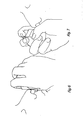
- the device is held in hand, suitably as shown in figs. 6 or 7, and the discharge tube is introduced into the patient's nostril whereafter the aerosol container is depressed to release a dosage of drug. Concurrently with said releasing the patient may inhale through the device. After use the device is returned to the storage position.
- the device of the invention may preferably be made to be disposed of after consumption of one aerosol container.
- the aerosol container may be exchangeable.
- the device is suitably provided with the aerosol container placed in the socket.
- the device according to the invention has a very compact design and may be hidden in the hand on use. The discreet use thus made possible has been found desirable to many patients.
- the compact design is enabled by the central positioning of the spindle means.
- the axis of the spindle means is thus close to a point half-way between the edges 10 and 11 of the socket, and a point half-way between the corresponding edges of the casing.
- a material for manufacture of the device is suitably a plastic material which may be shaped in a manner known per se.
- the casing can suitably be made of transparent material, rendering possible text on the aerosol container readable therethrough.
- the embodiment shown in the drawings is preferred, and it is suitably prepared by injection moulding of polypropylene for the socket and styrene acrylonitrile (SAN) for the casing.
- SAN styrene acrylonitrile
Abstract
Description
- The present invention is related to an aerosol dispensing device of the kind where an aerosol container is placed in a socket, through which an aerosol may be dispensed, and which is provided with a means protecting the dispensing opening and the aerosol container on storage. In particular,the invention is related to a device for administration of medicinally or hygienically active substances in aerosol form to the respiratory organs of a patient, primarily on administration into the nose. An object of the invention is to obtain an aerosol dispensing device having improved protection of the dispensing opening and the aerosol container. A further object is to obtain a device wherein the protective means does not incur a risk of disturbing the function of the device on aerosol dispensing.
- Administration of medicinally or hygienically active compounds in aerosol form is employed for treatment of the nasal cavities, the oral cavity, the throat and the inner parts of the respiratory organs. The aerosol is thereby usually provided in an aerosol container placed in a socket having a spray orifice from which doses of aerosol may be dispensed. Dispensing usually takes place by activation of the valve mechanism of the container by the patient, by depressing the end of the container into the socket. In order to avoid contamination of the dispensing opening of the device, said opening has often been provided with some kind of protective lid, which may have been combined with a protective means for the end of the container, which lid concurrently prevents inadvertent dispensing. Devices having such protective means are shown in e.g. U.S. Patent Specification No. 3 429 310 and British Patent Specification No. 1 402 636. The device according to the firstmentioned specification, in which a protective cover is both turnable and axially displaceable on a cylindrical socket, is impaired by risks of disturbed function in that the cover may seize or be locked on the socket, and turning and/or depression on aerosol dispensing is prevented. The manner of use may further not be obvious to the patient. Finally, the device does not permit a sufficient flow of air therethrough on aerosol dispensing. The device according to the second specification mentioned has a protective lid attached at the upper end of the socket via a flexible connecting member. Said protective cover requires a considerable space in the open position and may disturb the function of the device by falling down. On aerosol inhalation through the nose the lid will be positioned close to the eyes which is inconvenient to the patient.
- According to the present invention there is provided an aerosol dispensing device which fulfils the objects stated above, avoiding the drawbacks in previously known constructions and having the further advantage that the protective member, in the use position of the device, serves as a support and renders the device more secure and convenient to hold in hand.
- The aerosol dispensing device according to the invention comprises a socket, said socket having an open end opening across the longitudinal- direction thereof and being adapted to receive and hold an aerosol container ; said socket being closed at the opposite end thereof and having, in the interior thereof, a spraying nozzle adapted to interact with a dosage valve on the aerosol container, and further having a discharge tube For an aerosol; said socket having attached thereto a protective member moveable between a use position for the device and a storage position, at which the protective member covers the discharge tube as well as the open end of the socket and an aerosol container held therein. The device is characterized in that the protective member consists of a casing suspended rotably around two spindle means having a common axis extending through a central part of the socket, across the longitudinal direction thereof.
- According to a preferred embodiment of the invention the casing is lockable in the use position and preferably also in the storage position by means of interacting members on the casing and on the socket.
- The socket making part of the device according to the invention is adapted to receive an aerosol container. It should also allow passage of inhalation air along the sides of the aerosol container. Within the scope of the invention it is possible to vary the shape of the socket, which thus may have e.g. a round or oval cross-section. According to an especially preferred embodiment the socket has a rectangular, preferably a square cross-section. Thereby the socket will have two planar lateral surfaces on each side of the surface where the discharge tube is placed. The spindle means for the casing are then positioned on said lateral surfaces. With a corresponding design of the casing, where the lateral portions provided with spindle means are extended to plane parallel lateral walls, an improved tightening in the storage position and an improved control of the movement of the casing are achieved.
- The device of the present invention is further described with reference to the enclosed drawings, in which
- Fig. 1 shows a side view of a device according to an embodiment of the invention, in the use position, provided with an aerosol container,
- Fig. 2 shows a side view of the device according to fig. 1 in the storage position,
- Fig. 3 shows a view from above of a socket making part of the device according to fig. 1,
- Fig. 4 shows a section along the line IV-IV through the socket in fig. 3,
- Fig. 5 shows a view of a casing making part of the device according to fig. l, and
- Fig. 6 and Fig. 7 illustrate how a device according to the invention may be held in hand on dispensing of an aerosol.
- In the
drawings 1 denotes a socket. The socket consists of a hollow member having substantially square cross-section, theupper end 2 of which member is open and may receive anaerosol container 3, and the lower closedend 4 of which is provided with aninternal spraying nozzle 5. A dosage valve in the aerosol container opens into a tube fitted into the spraying nozzle. In front of and in line with the obliquely upwardly directed orifice of the spray nozzle adischarge tube 6 is arranged, designed to be introduceabla into the nostril of a patient. Two opposite lateral walls of thesocket 1 have, as spindle means, twostuds 7 placed substantially at the centre of said lateral walls. Said studs fit into two holes on acasing 9 to the formation of a joint, around which the casing is turnable between the use position and the storage position. Thelower edge 10 of the front wall of thesocket 1 is slightly extended in the forward direction in order to improve the tightening against thecasing 9. The diagonallyopposite edge 11 is extended to such extent that it cannot be introduced into the casing. Theedge 11 thus limits the mutual movability of the casing and the socket so that only the closed end of the socket may be swung through the casing. Thewall 12 of the casing is shaped like a rounded shell, which continues into two planar lateral walls wherein the holes 8 are made. An inwardly directedprojection 13 on each lateral wall of the casing fits into twocorresponding cavities planar support edge 16 and a concave wall section, which facilitate the handling of the device. - The device according to the invention may be carried locked in its storage position in the patient's pocket, handbag or the like. On use the device is held by the
casing 9. By pressing the closed end of the socket said socket is easily rotated through the casing and then locked in the use position. The device is held in hand, suitably as shown in figs. 6 or 7, and the discharge tube is introduced into the patient's nostril whereafter the aerosol container is depressed to release a dosage of drug. Concurrently with said releasing the patient may inhale through the device. After use the device is returned to the storage position. - The device of the invention may preferably be made to be disposed of after consumption of one aerosol container. In the alternative, the aerosol container may be exchangeable. The device is suitably provided with the aerosol container placed in the socket.
- The device according to the invention has a very compact design and may be hidden in the hand on use. The discreet use thus made possible has been found desirable to many patients. The compact design is enabled by the central positioning of the spindle means. In the device according to fig. 1 the axis of the spindle means is thus close to a point half-way between the
edges - Further, one may alternatively design the device thus that the open end of the socket, having the aerosol container held therein, may be swung through the casing.
- A material for manufacture of the device is suitably a plastic material which may be shaped in a manner known per se. The casing can suitably be made of transparent material, rendering possible text on the aerosol container readable therethrough.
- The embodiment shown in the drawings is preferred, and it is suitably prepared by injection moulding of polypropylene for the socket and styrene acrylonitrile (SAN) for the casing.
Claims (4)
Priority Applications (1)
| Application Number | Priority Date | Filing Date | Title |
|---|---|---|---|
| AT82850183T ATE20867T1 (en) | 1981-09-21 | 1982-09-16 | MEDICAL AEROSOL DISPENSING DEVICE. |
Applications Claiming Priority (2)
| Application Number | Priority Date | Filing Date | Title |
|---|---|---|---|
| SE8105544 | 1981-09-21 | ||
| SE8105544A SE434458B (en) | 1981-09-21 | 1981-09-21 | aerosol dispenser |
Publications (3)
| Publication Number | Publication Date |
|---|---|
| EP0075548A2 true EP0075548A2 (en) | 1983-03-30 |
| EP0075548A3 EP0075548A3 (en) | 1983-08-17 |
| EP0075548B1 EP0075548B1 (en) | 1986-07-23 |
Family
ID=20344583
Family Applications (1)
| Application Number | Title | Priority Date | Filing Date |
|---|---|---|---|
| EP82850183A Expired EP0075548B1 (en) | 1981-09-21 | 1982-09-16 | Medical aerosol dispensing device |
Country Status (15)
| Country | Link |
|---|---|
| EP (1) | EP0075548B1 (en) |
| JP (1) | JPS5861757A (en) |
| AT (1) | ATE20867T1 (en) |
| AU (1) | AU557695B2 (en) |
| CA (1) | CA1185137A (en) |
| DE (1) | DE3272156D1 (en) |
| DK (1) | DK157351C (en) |
| FI (1) | FI72879C (en) |
| GR (1) | GR78039B (en) |
| HK (1) | HK72089A (en) |
| IE (1) | IE53412B1 (en) |
| NO (1) | NO152486C (en) |
| PH (1) | PH23482A (en) |
| SE (1) | SE434458B (en) |
| SG (1) | SG41889G (en) |
Cited By (6)
| Publication number | Priority date | Publication date | Assignee | Title |
|---|---|---|---|---|
| WO1999025405A1 (en) * | 1997-11-14 | 1999-05-27 | Astrazeneca Ab | Inhalation device |
| WO2002085436A2 (en) * | 2001-04-20 | 2002-10-31 | Glaxo Group Limited | Medicament dispenser |
| WO2004041337A1 (en) * | 2002-11-07 | 2004-05-21 | Glaxo Group Limited | Device |
| GB2419292A (en) * | 2004-10-22 | 2006-04-26 | Graham Walker | Inhaler with hinged cap |
| US8251056B2 (en) | 2005-09-08 | 2012-08-28 | Glaxo Group Limited | Inhaler |
| US8397714B2 (en) | 2004-03-10 | 2013-03-19 | Glaxo Group Limited | Dispensing device |
Families Citing this family (2)
| Publication number | Priority date | Publication date | Assignee | Title |
|---|---|---|---|---|
| JP2513483Y2 (en) * | 1991-10-18 | 1996-10-09 | 村田機械株式会社 | Automatic guided vehicle |
| USD1010101S1 (en) | 2020-09-18 | 2024-01-02 | Trudell Medical International | Holding chamber |
Citations (3)
| Publication number | Priority date | Publication date | Assignee | Title |
|---|---|---|---|---|
| US2318636A (en) * | 1938-06-27 | 1943-05-11 | Louis W Schaaff | Apparatus for sweetening breath |
| GB1402638A (en) * | 1972-06-27 | 1975-08-13 | Allen & Hanburys Ltd | Device for dispensing medicaments from a pressurised dispensing container |
| US4111338A (en) * | 1976-03-16 | 1978-09-05 | 3C Chemical Laboratories Pty. Limited | Wall mounted actuator for aerosol can |
-
1981
- 1981-09-21 SE SE8105544A patent/SE434458B/en not_active IP Right Cessation
-
1982
- 1982-09-13 AU AU88326/82A patent/AU557695B2/en not_active Expired
- 1982-09-15 IE IE2251/82A patent/IE53412B1/en not_active IP Right Cessation
- 1982-09-16 DK DK413782A patent/DK157351C/en not_active IP Right Cessation
- 1982-09-16 AT AT82850183T patent/ATE20867T1/en not_active IP Right Cessation
- 1982-09-16 DE DE8282850183T patent/DE3272156D1/en not_active Expired
- 1982-09-16 EP EP82850183A patent/EP0075548B1/en not_active Expired
- 1982-09-20 JP JP57162455A patent/JPS5861757A/en active Granted
- 1982-09-20 FI FI823231A patent/FI72879C/en not_active IP Right Cessation
- 1982-09-20 GR GR69320A patent/GR78039B/el unknown
- 1982-09-20 NO NO823178A patent/NO152486C/en not_active IP Right Cessation
- 1982-09-20 CA CA000411767A patent/CA1185137A/en not_active Expired
- 1982-09-20 PH PH27891A patent/PH23482A/en unknown
-
1989
- 1989-07-12 SG SG418/89A patent/SG41889G/en unknown
- 1989-09-07 HK HK720/89A patent/HK72089A/en not_active IP Right Cessation
Patent Citations (3)
| Publication number | Priority date | Publication date | Assignee | Title |
|---|---|---|---|---|
| US2318636A (en) * | 1938-06-27 | 1943-05-11 | Louis W Schaaff | Apparatus for sweetening breath |
| GB1402638A (en) * | 1972-06-27 | 1975-08-13 | Allen & Hanburys Ltd | Device for dispensing medicaments from a pressurised dispensing container |
| US4111338A (en) * | 1976-03-16 | 1978-09-05 | 3C Chemical Laboratories Pty. Limited | Wall mounted actuator for aerosol can |
Cited By (9)
| Publication number | Priority date | Publication date | Assignee | Title |
|---|---|---|---|---|
| WO1999025405A1 (en) * | 1997-11-14 | 1999-05-27 | Astrazeneca Ab | Inhalation device |
| US6273084B1 (en) | 1997-11-14 | 2001-08-14 | Astra Aktiebolag | Inhalation device |
| WO2002085436A2 (en) * | 2001-04-20 | 2002-10-31 | Glaxo Group Limited | Medicament dispenser |
| WO2002085436A3 (en) * | 2001-04-20 | 2003-01-30 | Glaxo Group Ltd | Medicament dispenser |
| WO2004041337A1 (en) * | 2002-11-07 | 2004-05-21 | Glaxo Group Limited | Device |
| US7552728B2 (en) | 2002-11-07 | 2009-06-30 | Glaxo Group Limited | Drug delivery device |
| US8397714B2 (en) | 2004-03-10 | 2013-03-19 | Glaxo Group Limited | Dispensing device |
| GB2419292A (en) * | 2004-10-22 | 2006-04-26 | Graham Walker | Inhaler with hinged cap |
| US8251056B2 (en) | 2005-09-08 | 2012-08-28 | Glaxo Group Limited | Inhaler |
Also Published As
| Publication number | Publication date |
|---|---|
| SG41889G (en) | 1989-12-22 |
| AU557695B2 (en) | 1987-01-08 |
| FI72879B (en) | 1987-04-30 |
| HK72089A (en) | 1989-09-14 |
| NO152486C (en) | 1985-10-09 |
| DK157351C (en) | 1990-05-14 |
| IE822251L (en) | 1983-03-21 |
| EP0075548B1 (en) | 1986-07-23 |
| EP0075548A3 (en) | 1983-08-17 |
| NO152486B (en) | 1985-07-01 |
| GR78039B (en) | 1984-09-26 |
| DK157351B (en) | 1989-12-27 |
| FI823231A0 (en) | 1982-09-20 |
| IE53412B1 (en) | 1988-11-09 |
| AU8832682A (en) | 1983-03-31 |
| JPS645911B2 (en) | 1989-02-01 |
| CA1185137A (en) | 1985-04-09 |
| DK413782A (en) | 1983-03-22 |
| DE3272156D1 (en) | 1986-08-28 |
| NO823178L (en) | 1983-03-22 |
| SE8105544L (en) | 1983-03-22 |
| PH23482A (en) | 1989-08-07 |
| JPS5861757A (en) | 1983-04-12 |
| FI823231L (en) | 1983-03-22 |
| SE434458B (en) | 1984-07-30 |
| FI72879C (en) | 1987-08-10 |
| ATE20867T1 (en) | 1986-08-15 |
Similar Documents
| Publication | Publication Date | Title |
|---|---|---|
| EP0015247B1 (en) | An aerosol inhalation device | |
| EP0333334B1 (en) | Dispensers for powdered medication | |
| US7367333B2 (en) | Inhalation device | |
| US4570630A (en) | Medicament inhalation device | |
| EP0079478A1 (en) | Medicament inhalation device | |
| JPH0257942B2 (en) | ||
| HU209475B (en) | Device for the administration of powdered medicinal substances | |
| US20070074718A1 (en) | Metered dose inhaler having spacing device | |
| JP2927506B2 (en) | Disposable medicine inhaler | |
| US6595204B2 (en) | Spacer for an inhaler | |
| JP2002506686A (en) | Inhalation device | |
| GB2301040A (en) | Inhaler with collapsible or telescopic chamber. | |
| US4114811A (en) | Spray dispenser with easily actuable mouthpiece | |
| EP0075548B1 (en) | Medical aerosol dispensing device | |
| US6397837B1 (en) | Inhaler assistive device | |
| US6453900B1 (en) | Inhaler device |
Legal Events
| Date | Code | Title | Description |
|---|---|---|---|
| PUAI | Public reference made under article 153(3) epc to a published international application that has entered the european phase |
Free format text: ORIGINAL CODE: 0009012 |
|
| AK | Designated contracting states |
Designated state(s): AT BE CH DE FR GB IT LI LU NL SE |
|
| PUAL | Search report despatched |
Free format text: ORIGINAL CODE: 0009013 |
|
| AK | Designated contracting states |
Designated state(s): AT BE CH DE FR GB IT LI LU NL SE |
|
| 17P | Request for examination filed |
Effective date: 19830905 |
|
| GRAA | (expected) grant |
Free format text: ORIGINAL CODE: 0009210 |
|
| ITF | It: translation for a ep patent filed |
Owner name: BARZANO' E ZANARDO ROMA S.P.A. |
|
| AK | Designated contracting states |
Kind code of ref document: B1 Designated state(s): AT BE CH DE FR GB IT LI LU NL SE |
|
| REF | Corresponds to: |
Ref document number: 20867 Country of ref document: AT Date of ref document: 19860815 Kind code of ref document: T |
|
| REF | Corresponds to: |
Ref document number: 3272156 Country of ref document: DE Date of ref document: 19860828 |
|
| ET | Fr: translation filed | ||
| PLBE | No opposition filed within time limit |
Free format text: ORIGINAL CODE: 0009261 |
|
| STAA | Information on the status of an ep patent application or granted ep patent |
Free format text: STATUS: NO OPPOSITION FILED WITHIN TIME LIMIT |
|
| 26N | No opposition filed | ||
| ITTA | It: last paid annual fee | ||
| EPTA | Lu: last paid annual fee | ||
| EAL | Se: european patent in force in sweden |
Ref document number: 82850183.3 |
|
| PGFP | Annual fee paid to national office [announced via postgrant information from national office to epo] |
Ref country code: NL Payment date: 20010618 Year of fee payment: 20 |
|
| PGFP | Annual fee paid to national office [announced via postgrant information from national office to epo] |
Ref country code: LU Payment date: 20010627 Year of fee payment: 20 |
|
| PGFP | Annual fee paid to national office [announced via postgrant information from national office to epo] |
Ref country code: GB Payment date: 20010807 Year of fee payment: 20 Ref country code: AT Payment date: 20010807 Year of fee payment: 20 |
|
| PGFP | Annual fee paid to national office [announced via postgrant information from national office to epo] |
Ref country code: SE Payment date: 20010831 Year of fee payment: 20 Ref country code: FR Payment date: 20010831 Year of fee payment: 20 |
|
| PGFP | Annual fee paid to national office [announced via postgrant information from national office to epo] |
Ref country code: DE Payment date: 20010927 Year of fee payment: 20 Ref country code: CH Payment date: 20010927 Year of fee payment: 20 |
|
| PGFP | Annual fee paid to national office [announced via postgrant information from national office to epo] |
Ref country code: BE Payment date: 20011010 Year of fee payment: 20 |
|
| REG | Reference to a national code |
Ref country code: GB Ref legal event code: IF02 |
|
| PG25 | Lapsed in a contracting state [announced via postgrant information from national office to epo] |
Ref country code: LI Free format text: LAPSE BECAUSE OF EXPIRATION OF PROTECTION Effective date: 20020915 Ref country code: GB Free format text: LAPSE BECAUSE OF EXPIRATION OF PROTECTION Effective date: 20020915 Ref country code: CH Free format text: LAPSE BECAUSE OF EXPIRATION OF PROTECTION Effective date: 20020915 |
|
| PG25 | Lapsed in a contracting state [announced via postgrant information from national office to epo] |
Ref country code: NL Free format text: LAPSE BECAUSE OF EXPIRATION OF PROTECTION Effective date: 20020916 Ref country code: LU Free format text: LAPSE BECAUSE OF EXPIRATION OF PROTECTION Effective date: 20020916 Ref country code: AT Free format text: LAPSE BECAUSE OF EXPIRATION OF PROTECTION Effective date: 20020916 |
|
| BE20 | Be: patent expired |
Owner name: A.B. *DRACO Effective date: 20020916 |
|
| REG | Reference to a national code |
Ref country code: GB Ref legal event code: PE20 Effective date: 20020915 |
|
| REG | Reference to a national code |
Ref country code: CH Ref legal event code: PL |
|
| EUG | Se: european patent has lapsed |
Ref document number: 82850183.3 |
|
| NLV7 | Nl: ceased due to reaching the maximum lifetime of a patent |
Effective date: 20020916 |