EP0075482A2 - Knickgelenktes Bodenbewegungsfahrzeug - Google Patents
Knickgelenktes Bodenbewegungsfahrzeug Download PDFInfo
- Publication number
- EP0075482A2 EP0075482A2 EP82304967A EP82304967A EP0075482A2 EP 0075482 A2 EP0075482 A2 EP 0075482A2 EP 82304967 A EP82304967 A EP 82304967A EP 82304967 A EP82304967 A EP 82304967A EP 0075482 A2 EP0075482 A2 EP 0075482A2
- Authority
- EP
- European Patent Office
- Prior art keywords
- frame section
- rear frame
- section
- vehicle
- ground engaging
- Prior art date
- Legal status (The legal status is an assumption and is not a legal conclusion. Google has not performed a legal analysis and makes no representation as to the accuracy of the status listed.)
- Withdrawn
Links
Images

Classifications
-
- B—PERFORMING OPERATIONS; TRANSPORTING
- B62—LAND VEHICLES FOR TRAVELLING OTHERWISE THAN ON RAILS
- B62D—MOTOR VEHICLES; TRAILERS
- B62D53/00—Tractor-trailer combinations; Road trains
- B62D53/02—Tractor-trailer combinations; Road trains comprising a uniaxle tractor unit and a uniaxle trailer unit
-
- E—FIXED CONSTRUCTIONS
- E02—HYDRAULIC ENGINEERING; FOUNDATIONS; SOIL SHIFTING
- E02F—DREDGING; SOIL-SHIFTING
- E02F3/00—Dredgers; Soil-shifting machines
- E02F3/04—Dredgers; Soil-shifting machines mechanically-driven
- E02F3/76—Graders, bulldozers, or the like with scraper plates or ploughshare-like elements; Levelling scarifying devices
- E02F3/7636—Graders with the scraper blade mounted under the tractor chassis
- E02F3/764—Graders with the scraper blade mounted under the tractor chassis with the scraper blade being pivotable about a vertical axis
-
- E—FIXED CONSTRUCTIONS
- E02—HYDRAULIC ENGINEERING; FOUNDATIONS; SOIL SHIFTING
- E02F—DREDGING; SOIL-SHIFTING
- E02F9/00—Component parts of dredgers or soil-shifting machines, not restricted to one of the kinds covered by groups E02F3/00 - E02F7/00
- E02F9/02—Travelling-gear, e.g. associated with slewing gears
-
- E—FIXED CONSTRUCTIONS
- E02—HYDRAULIC ENGINEERING; FOUNDATIONS; SOIL SHIFTING
- E02F—DREDGING; SOIL-SHIFTING
- E02F9/00—Component parts of dredgers or soil-shifting machines, not restricted to one of the kinds covered by groups E02F3/00 - E02F7/00
- E02F9/08—Superstructures; Supports for superstructures
- E02F9/0841—Articulated frame, i.e. having at least one pivot point between two travelling gear units
Definitions
- the present invention relates to an articulated earth-working vehicle.
- Earth-working machines such as motor graders, are commonly used for smoothing roads, terracing, and other grading operations. However, such machines have heretofore not been economically adaptable for uses other than grading.
- front end loaders, ditch digging machines and the like are also typically single purpose machines. Thus, a contractor usually has to invest substantial amounts of capital in several single purpose machines.
- an earth-working vehicle comprising a rear frame section capable of free standing against sideward swinging relative to the longitudinal axis of the rear frame section, a front frame section disconnectably articulated at its rear end to the rear frame section by an articulation joint, rear ground engaging wheels which are carried by an axle assembly which is fixedly secured to said rear frame section, a power section and the controls for the vehicle being mounted on the rear frame section, front ground engaging wheels being mounted on the forward end of the front frame section and an earth working tool extending downwardly from the front frame section.
- Such a vehicle is adaptable to at least several uses and functions, so that substantial amounts of investment capital can be saved. Because the front and rear frame structures are disconnectible, various front frame structures including different earth-working tools, such as a front end loader, ditcher, or the like can be economically adapted to a single rear frame structure.
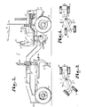
- the illustrated vehicle 1 has a rear frame structure 2 comprising a power section and including an operator's station 3.
- a front frame structure 4 is connected to the rear frame structure and carries an earth-working tool 5.
- An articulating joint 6 connects the front and rear frame structures together and is disconnectable, whereby various tools and front frame structures can be economically and interchangeably attached to the rear frame structure, thereby using a single power section and operator's station for a variety of purposes.
- the rear frame structure 2 has a rear end 9, intermediate portion 10 and forward end 11, and includes the power section which has an enclosure 12 on the rear end 9 concealing a suitable engine 13 ( Figure 2), connected to a transmission (not shown).
- a suitable engine 13 Figure 2
- suitable hydraulic pumps are driven by the engine 13 for powering various rams, described below, to control positioning of the earth-working tools.
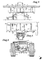
- a single set of ground engaging wheels 15 is suitably mounted on an axle assembly 16 and driven by the engine 13. Tandem wheels may alternatively be employed.
- the axle assembly 16 is fixed relative to the rear frame structure 2, so that the rear frame structure is independently movable and does not tend to heel or tip over on a swing axle, as is common in many types of earth working equipment.
- spaced brackets 45 and 46 connect the axle assembly 16 to the rear frame structure 2 in a fixed relationship.
- the axle assembly 16 may include as a part of the standard configuration of the rear frame structure 2, a bearing means in the form of a main rocker or pivot 47 suitably connected to the supporting frame portions of the frame structure 2 and received within a bearing eye 48 centered in the axle assembly 16, thereby facilitating side-to-side swinging or heeling over of the rear frame structure 2 relative to the axle assembly 16.
- the axle assembly is fixed, as by the brackets 45 and 46.
- Each of the brackets 45 and 46 comprises an elongate, L-shaped plate 50 having upwardly extending gussets 51, the plate 50 being positioned against a beam wall 52 of the rear frame structure 2.
- the gussets 51 are inset on the plate 50, leaving a lip 54 which extends under the beam wall 52 and is secured thereto, as by fasteners 55.
- a web 56 extends between the gussets 51 and at a right angle to the plate 50 and is also secured to the beam wall 52, as by fasteners 57.
- Flanges 59 extend from the axle assembly 16 and fasteners, such as bolts 58,secure the plate 50 to the axle assembly, thereby interconnecting the rear frame structure 2 and axle assembly 16 in a fixed relationship.
- a spacer plate 60 secured to the underside of the plate 50 correctly positions the bracket 45 relative to the axle assembly 16.
- the operator's station 3 is mounted generally over the forward end 11 and includes a platform 17, a forwardly facing operator's seat 18 and a console 19. Mounted on the console 19 is a steering wheel 20 and a bank of joystick levers 21 for controlling operation of the various hydraulic rams.
- a roll-over protection structure 23 is rigidly mounted on the rear frame structure 2 and extends over the operator's station 3 for at least partial shielding from the elements and to protect the operator from falling objects, roll-overs and the like.
- the articulating joint 6 is situated substantially under the operator's station 3 and includes upper and lower, axially aligned vertically oriented king pins 25, suitably mounted on ears 26 respectively extending from the forward end 11 of the rear frame structure 2 and from the front frame structure 4 as described below.
- the attachment of the articulating joint 6 is disconnectable, so that one can separate the front frame structure 4 from.the rear frame structure 2 and interchangeably attach front frame structures of various other configurations (not shown) and having earth engaging tools or devices thereon, such as ditch diggers, front end loaders and the like for various other purposes.
- the exemplary front frame structure 4 is a grader and has a forward end 28, an intermediate tool carrier section 29, and a rear end 30.
- Front ground engaging wheels 31 and a swing mounted or non-fixed axle assembly 32 are mounted at the forward end 28 for smooth, planar grading and are associated with appropriate steering means, including a hydraulic ram 33 to turn the wheels 31 up to approximately 50 degrees left or right ( Figures 3 and 4).
- Appropriate means are also included in conjunction with the forward end 28 to cause coordinated sideward tilting of the front wheels 31.
- the wheels 31 can be turned relative to the rear wheels 15 so as to cause the earth-working vehicle 1 to turn, first turning the front frame structure 4 and tending to pull the rear frame structure 2 therearound.
- the front frame structure 4 can be angled relative to the rear frame structure 2, and the front wheels 31 aligned in the same direction as the rear wheels 15, thereby crabbing the front and rear wheels relative to each other, as for grading a ditch or the like.
- the operator's station 3 does not tend to turn with the front frame structure 4 but remains rigidly mounted on the rear frame structure 2.
- the operator is provided with a safe, straight-ahead view of superior visibility as the vehicle moves, rather than the operator travelling sidewardly, as would be the case if the operator's station was on or aligned with the front frame structure.
- the tool 5 is a scraper blade 35 and is suitably mounted on a turntable arrangement 36 connected by a drag beam 37 to the forward end 28.
- Left and right elevation rams 39 extend between the tool carrier section 29 and the turntable arrangement 36, and a ram 40 is suitably mounted via a linkage arrangement 41 to cause sideward shifting of the scraper blade 35.
- a gear box arrangement 42 provides rotation of the blade 35.
- Suitable hydraulic conduits 43 having quick disconnect fittings extend from the various rams 33, 39 and 40 to the controls 21 and the hydraulic pump.
- the ears 26 for the articulated joint 6 extend from the rear end 30 of the front frame structure-4 and are suitably affixed to the king pins 25.
- the above described articulated earth-working vehicle 1 provides economical interchangeability of the front frame structure 4-and tool 5 with other variously configured front frame structures and tools adapted for jobs other than scraping or grading.
- the operator's station 3 and console 19 remain with the power components of the rear frame structure 2 to enable interchangeability.
- the quick disconnect fittings of the hydraulic conduits 43 enable relatively rapid changeover of hydraulic power lines.
- the positioning of the operator's station 3, as described above, provides superior visibility to other known motor graders, as well as the aforementioned interchangeability of working parts.
Landscapes
- Engineering & Computer Science (AREA)
- Mining & Mineral Resources (AREA)
- Civil Engineering (AREA)
- General Engineering & Computer Science (AREA)
- Structural Engineering (AREA)
- Mechanical Engineering (AREA)
- Chemical & Material Sciences (AREA)
- Combustion & Propulsion (AREA)
- Transportation (AREA)
- Body Structure For Vehicles (AREA)
Applications Claiming Priority (4)
| Application Number | Priority Date | Filing Date | Title |
|---|---|---|---|
| US30437681A | 1981-09-22 | 1981-09-22 | |
| US304376 | 1981-09-22 | ||
| US39753282A | 1982-07-12 | 1982-07-12 | |
| US397532 | 1982-07-12 |
Publications (2)
| Publication Number | Publication Date |
|---|---|
| EP0075482A2 true EP0075482A2 (de) | 1983-03-30 |
| EP0075482A3 EP0075482A3 (de) | 1983-11-16 |
Family
ID=26973989
Family Applications (1)
| Application Number | Title | Priority Date | Filing Date |
|---|---|---|---|
| EP82304967A Withdrawn EP0075482A3 (de) | 1981-09-22 | 1982-09-21 | Knickgelenktes Bodenbewegungsfahrzeug |
Country Status (3)
| Country | Link |
|---|---|
| EP (1) | EP0075482A3 (de) |
| AU (1) | AU8857282A (de) |
| GB (1) | GB2106567A (de) |
Cited By (2)
| Publication number | Priority date | Publication date | Assignee | Title |
|---|---|---|---|---|
| WO2011134012A1 (en) * | 2010-04-29 | 2011-11-03 | Xpress Drilling Services Pty Ltd | Roll over protection device |
| AU2012100147B4 (en) * | 2010-04-29 | 2012-05-24 | Xpress Drilling Services Pty Ltd | Roll Over Protection Device |
Family Cites Families (4)
| Publication number | Priority date | Publication date | Assignee | Title |
|---|---|---|---|---|
| US2949162A (en) * | 1955-12-22 | 1960-08-16 | Davis Engineering Inc | Carriage and driving mechanism for a mobile boom machine |
| US3157239A (en) * | 1961-09-07 | 1964-11-17 | Gen Motors Corp | Four wheel drive, two-engine, articulated frame tractor |
| US3526329A (en) * | 1967-09-26 | 1970-09-01 | Caterpillar Tractor Co | Bucket attachment for wheel loaders |
| US3527315A (en) * | 1968-05-09 | 1970-09-08 | Allis Chalmers Mfg Co | Articulated motor grader |
-
1982
- 1982-09-21 AU AU88572/82A patent/AU8857282A/en not_active Abandoned
- 1982-09-21 EP EP82304967A patent/EP0075482A3/de not_active Withdrawn
- 1982-09-21 GB GB08226963A patent/GB2106567A/en not_active Withdrawn
Cited By (2)
| Publication number | Priority date | Publication date | Assignee | Title |
|---|---|---|---|---|
| WO2011134012A1 (en) * | 2010-04-29 | 2011-11-03 | Xpress Drilling Services Pty Ltd | Roll over protection device |
| AU2012100147B4 (en) * | 2010-04-29 | 2012-05-24 | Xpress Drilling Services Pty Ltd | Roll Over Protection Device |
Also Published As
| Publication number | Publication date |
|---|---|
| GB2106567A (en) | 1983-04-13 |
| EP0075482A3 (de) | 1983-11-16 |
| AU8857282A (en) | 1983-03-31 |
Similar Documents
| Publication | Publication Date | Title |
|---|---|---|
| US6397967B1 (en) | Skid steer vehicle | |
| US6360459B1 (en) | Tiltable bucket assembly | |
| EP0166704B1 (de) | Zusatzgerät für Radlader und ähnliche Maschinen | |
| US6772544B2 (en) | Wheeled work vehicle | |
| US3512589A (en) | Earth moving apparatus | |
| US4833797A (en) | Trencher attachment | |
| US3450213A (en) | Scraper implement | |
| KR950011779A (ko) | 유압식 굴삭기 | |
| US5732781A (en) | Mechanism to laterally tilt front end loader buckets | |
| US5295318A (en) | Backhoe-loader | |
| US4161987A (en) | Tractor grader | |
| US4444542A (en) | Vehicle with double booms | |
| US4378193A (en) | Mobile shovel excavator | |
| US3653131A (en) | Excavating apparatus | |
| US4304305A (en) | Frame for mounting tilt and angled dozer blade to tractors | |
| US4501334A (en) | Wheeled excavator having a dozer blade and a boom-mounted stabilizer wheel | |
| EP0075482A2 (de) | Knickgelenktes Bodenbewegungsfahrzeug | |
| US6711839B1 (en) | Tractor with a working implement | |
| US4274213A (en) | Scraper blade mounting assembly | |
| US5195863A (en) | Excavator loader | |
| US3429380A (en) | Folding slope grader for bulldozers | |
| US2883772A (en) | Materials handling machine | |
| US4140186A (en) | Heavy-duty ripper for dual traction unit | |
| US6625908B1 (en) | Apparatus for digging a trench | |
| US4930589A (en) | Operator guidebar for a walk-beside articulated machine |
Legal Events
| Date | Code | Title | Description |
|---|---|---|---|
| PUAI | Public reference made under article 153(3) epc to a published international application that has entered the european phase |
Free format text: ORIGINAL CODE: 0009012 |
|
| AK | Designated contracting states |
Designated state(s): AT BE CH DE FR GB IT LI LU NL SE |
|
| RAP1 | Party data changed (applicant data changed or rights of an application transferred) |
Owner name: HAULMASTERS, INC. |
|
| RAP1 | Party data changed (applicant data changed or rights of an application transferred) |
Owner name: ROYAL TRACTOR COMPANY, INC. |
|
| PUAL | Search report despatched |
Free format text: ORIGINAL CODE: 0009013 |
|
| AK | Designated contracting states |
Designated state(s): AT BE CH DE FR GB IT LI LU NL SE |
|
| STAA | Information on the status of an ep patent application or granted ep patent |
Free format text: STATUS: THE APPLICATION IS DEEMED TO BE WITHDRAWN |
|
| 18D | Application deemed to be withdrawn |
Effective date: 19840821 |
|
| RIN1 | Information on inventor provided before grant (corrected) |
Inventor name: HARDWICK, LEE R. |