EP0075407B1 - Helicopter rotor - Google Patents
Helicopter rotor Download PDFInfo
- Publication number
- EP0075407B1 EP0075407B1 EP82304668A EP82304668A EP0075407B1 EP 0075407 B1 EP0075407 B1 EP 0075407B1 EP 82304668 A EP82304668 A EP 82304668A EP 82304668 A EP82304668 A EP 82304668A EP 0075407 B1 EP0075407 B1 EP 0075407B1
- Authority
- EP
- European Patent Office
- Prior art keywords
- rotor
- spindle
- hub
- further characterised
- tracks
- Prior art date
- Legal status (The legal status is an assumption and is not a legal conclusion. Google has not performed a legal analysis and makes no representation as to the accuracy of the status listed.)
- Expired
Links
Images


Classifications
-
- B—PERFORMING OPERATIONS; TRANSPORTING
- B64—AIRCRAFT; AVIATION; COSMONAUTICS
- B64C—AEROPLANES; HELICOPTERS
- B64C27/00—Rotorcraft; Rotors peculiar thereto
- B64C27/54—Mechanisms for controlling blade adjustment or movement relative to rotor head, e.g. lag-lead movement
- B64C27/58—Transmitting means, e.g. interrelated with initiating means or means acting on blades
- B64C27/59—Transmitting means, e.g. interrelated with initiating means or means acting on blades mechanical
Definitions
- This invention relates to helicopter rotors.
- One known type of helicopter rotor control system includes pitch control means in the form of a centrally located control spindle.
- a lower end of the spindle is connected to cyclic and collective inputs operable by the pilot, and an upper end is connected to radially extending spider arms equal in number to the number of rotor blades.
- the spider arms are connected by adjustable connecting rods to pitch control arms attached to the rotor blades.
- cyclic pitch changes are accomplished by tilting of the lower end of the spindle in any direction, and collective pitch changes by axial movements of the spindle. Because such movements have to be capable of being accomplished simultaneously, a support means for the spindle, normally located intermediate the ends of the spindle, has also to be capable of simultaneous tilting and axial movements whilst rotating about the axis.
- FR-A-888,051 proposes the use of a spherical bearing type of universal joint for an equivalent purpose, as does a!soGB ⁇ A ⁇ 811,211. !t has also been proposed to use a universal joint of this type at the upper end of the control spindle to accommodate the tilting movements of the latter, the universal joint itself being arranged internally of a piston slidably mounted in the rotor hub so as to permit the universal joint to move to accommodate axial movements of the spindle.
- torque to rotate the control spindle is transmitted through spring means attached to surfaces of one of the spider arms contacting the surface of a slot in the rotor drive shaft through which the spider arm is located.
- control spindle support means comprises a fabricated universal joint arranged intermediate the ends of the spindle and attached internally of a sleeve that is rotatably supported internally of the rotor hub, to provide for tilting movements.
- Axial movements are catered for by axially extending splines formed externally on a skirt portion of the sleeve and engaged in a splined ring supported from the rotor hub, and torque is transmitted from the rotor hub through the splines and the universal joint to rotate the control spindle.
- pitch control means in the form of a swash plate having a non-rotatable ring connected to a plurality of radially spaced-apart control rods and a rotatable ring connected either through radially extending spider arms or directly by adjustable connecting rods to pitch control arms attached to the blades.
- a support means is necessary to support the swash plate.
- this has comprised a part spherical annular bearing to provide for tilting of the swash plate for cyclic pitch changes, the bearing being mounted for vertical sliding movement in order to effect collective pitch changes.
- An objective of the present invention is therefore to provide a helicopter rotor having a control system that avoids much of the complexity, cost and weight penalties of known systems.
- the invention provides a helicopter rotor including a rotor hub adapted for rotation about an axis and supporting a plurality of generally radially extending rotor blades, and pitch control means adapted to change the pitch of the rotor blades both cyclically and collectively and including support means comprising a universal joint located concentrically of the axis of rotation, characterised in that said universal joint includes three equi-spaced radially extending pins attached to a rotating hub portion and each supporting a radially slidable and rotatable bearing having a spherical external surface, the bearings being located in generally axially extending tracks on another rotating hub portion, these tracks having a circular cross-sectional shape for rolling engagement by the bearings upon relative axial movement between the bearings and the tracks of the respective rotating hub portions for the purpose of changing the pitch of the rotor blades.
- the universal joint may be located intermediate the ends of a central control spindle having an upper end operatively attached to the rotor blades and a lower end operatively attached to input control means.
- the pins may extend radially outwardly from an outer surface of the spindle and the tracks may be formed internally of an annular housing attached to the rotor hub.
- the pins may be formed integral with the spindle.
- the central control spindle is hollow with an internal surface flared outwardly towards each end, a stationary hollow shaft extending through the spindle and upwardly through the rotor hub.
- the stationary hollow shaft is adapted to support equipment above the rotor.
- the universal joint may be located internally of a swash plate having a rotatable inner ring operatively attached to the rotor blades and a non-rotatable outer ring operatively attached to input control means.
- the pins may extend radially outwardly from a central spindle attached to the rotor hub and the locating tracks may be formed internally of the swash plate rotatable ring.
- a helicopter rotor generally indicated at 10 comprises a hollow rotor hub 11 mounted on a gearbox (not shown) for rotation about a generally vertical axis 12.
- the hub 11 includes a plurality of radially extending arms 13 each adapted to support a rotor blade (not shown) in a manner permitting rotation of the blade about its longitudinal axis to provide for changes in the blade pitch during operation.
- Blade pitch control means generally indicated at 14, includes a generally vertical control spindle 15 located centrally of the rotor hub 11.
- a lower end (not shown) of control spindle 15 is connected through a suitable bearing to control means operable by the pilot, and an upper end supports a plurality of radially extending spider arms 16.
- Each of the arms 16 extends through an aperture 17 in the hub 11 and terminates at an outer end pivotally connected to one end of a generally vertical, adjustable control rod 18, the other end of which is pivotally connected to a pitch control lever 19 operatively associated with one of the rotor blades.
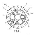
- Control spindle 15 is supported internally of the hub 11 intermediate its upper and lower ends by support means generally indicated at 20 ( Figures 1 and 2) which permits both tilting and vertical movements of the spindle 15 as well as simultaneous tilting and vertical movements.
- Support means 20 comprises a universal joint 21 having three equi-spaced radially extending pins 22 formed integral with the spindle 15. Each pin 22 supports a dry bearing 23 which carries a rotatable bearing 24 having a part spherical external surface 25.
- the bearings 24 are each located in an axially extending track 26 formed internally of an annular housing 27 fixedly attached to hub 11 through a bolted external flange 28.
- the tracks 26 have a part-circular cross-sectional shape ( Figure 2) having a radius corresponding approximately with the radius of the part-spherical surface 25 of the bearings 24, the parts being constructed so that axial movement in the tracks 26 is accomplished by rolling of the bearings 24 on the pins 22.
- the bearings 24 are capable of axial movement in the tracks 26 as well as radial sliding movement on the dry bearings 23, thereby permitting simultaneous tilting and axial movements of the spindle 15 whilst also transmitting torque from the rotor hub to the control spindle.
- a helicopter rotor generally indicated at 29 includes a rotor hub 30 bolted to the top of a hollow drive shaft 31 for rotation about a generally vertical axis 32.
- the hub 30 supports a plurality of elastomeric bearings 33, each of the bearings 33 providing support for a radially extending rotor blade (not shown) in a manner to permit rotation of the blades about a longitudinal axis thereof to provide for blade pitch change movements.
- Pitch control means is located centrally of the shaft 31 and comprises a swash plate 35 having an inner rotatable ring 36 supporting bearings 37 which carry an outer non-rotatable ring 38.
- Three generally vertical input control rods 39 are pivotally attached to lugs 40 extending radially outwardly from a circumferential region of non-rotatable ring 38.
- the inner rotatable ring 36 is extended upwardly and supports a plurality of radially extending spider arms 41 equal in number to the number of rotor blades, and which protrude through apertures 42 in the wall of the shaft 31 for pivotal attachment to generally vertically extending adjustable control rods 43 attached to pitch control levers (not shown) operatively associated with the rotor blades.
- Support means is located centrally of the swash plate 35 to maintain the swash plate concentric of axis 32, and comprises a universal joint 45 similar to the universal joint 21 previously described with reference to the embodiment of Figures 1 and 2. Like reference numerals will be used to identify similar parts.
- the three pins 22 are formed integral with one end of a hollow spindle 46 depending from a bolted attachment to the rotor hub 30 and a hollow stationary shaft 47 is located through the spindle 46 concentrically of the axis of rotation 32 and is extended upwardly to protrude from an upper surface of the rotor hub 30.
- the tracks 26 for the part-spherical bearings 24 carried by the spindles 22 are formed on an inner surface of the rotating ring 36.
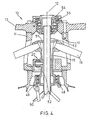
- FIG 4 The embodiment of Figure 4 is a modification of that previously described with reference to Figures 1 and 2.
- the hollow central control spindle 15 is shortened so as to be generally symmetrical in length about the support means generally indicated at 20 which is identical to the support means 20 of Figures 1 and 2.
- the lower end of control spindle 15 supports bearings 48 which in turn support a non-rotatable ring 49 operatively connected to a plurality of input control rods 50 (one only being shown).
- the internal surface of the spindle 15 flares outwardly towards each end as indicated at 51 and 52 respectively.
- the lower end of a hollow shaft 53 is rotationally fixed to non-rotating structure (not shown), and the shaft 53 is extended upwardly through the spindle 15 to terminate at an upper end which is rotationally fixed to a flanged boss 54 supported in bearings 55 located in a central aperture in the arms 13 of the rotor hub 11.
- tilting of the lower end of spindle 15 in any direction is permitted by a combination of axial and radial movements of the bearings 24 in the tracks 26, and is thereby transmitted through the arms 16, control rods 18 and pitch control levers 19 to change the pitch of the rotor blades cyclically as the rotor hub is rotated about axis 12.
- Axial movement of the spindle 15 is permitted by rolling of the bearings 24 in the tracks 26 to change the pitch of the rotor blades collectively, and it will be understood that these tilting and axial movements can be achieved simultaneously to provide for simultaneous collective and cyclic pitch changes of the rotor blades.
- tilting and axial movement of the swash plate 35 to effect cyclic and collective pitch changes is accomplished by appropriate vertical movements of the control rods 39. These movements are permitted in a manner similar to that previously described in relation to the embodiment of Figures 1 and 2 except that in this case it is the track bearing member (i.e. the inner rotatable ring 36) which is caused to move relative to the pins 22.
- the track bearing member i.e. the inner rotatable ring 36
- axial movement of the swash plate 35 is permitted by . rolling of the bearings 24 along the tracks 26, and tilting is permitted by a combination of the same rolling movement and a radial sliding movement of the bearings 24 along the pins 22.
- the universal joints 20 and 43 respectively, also serve to transmit torque from the rotating rotor hub to the pitch control means to ensure correct operational alignment of the spider arms 16 and 41 with the rotating rotor blades.
- a helicopter rotor incorporates a control system which includes a simple, efficient and compact support means to accommodate the aforementioned tilting and axial movements of a rotor blade pitch control means as well as providing the necessary torque transmission.
- a single assembly having a minimal number of parts, thereby minimising weight and cost.
- the aforementioned fabricated support means with the axial splines has twenty-two machined parts together with twenty attachment bolts and nuts, whereas the present support means consists of seven parts only, and represents a weight saving of about fifteen pounds (6.8 kg).
- the support means provides smooth vibration free running and constant angular motion regardless of its inclination, so that the central spider is relieved of undesirable accelerations that may be caused by Coriolis forces during operation.
- support means 20 and 44 as well as, in the embodiment of Figures 1 and 2, the use of dry bearings 23, minimises maintenance requirements and simplifies maintenance procedures.
- the compact nature of support means 20 and 44 is also of advantage in that it permits either a reduction in the rotor hub diameter, thereby further reducing weight or, in the embodiments of Figures 1, 2, and 4 the incorporation of a stiffer yet lighter control spindle 15.
- a rotor according to the invention offers more space internally of a rotor hub as illustrated in Figures 3 and 4 which can be used advantageously to mount and supply ancillary equipment above the rotor hub.
- conventional rotor facilities such as blade fold mechanisms and blade de-icing systems can be supplied and controlled by means routed through the stationary central shafts 47 and 53 respectively.
- the support means 20 and 44 is self-centering when the bearings 24 are located in the tracks 26, shimming to control play is eliminated, thereby simplifying both assembly and maintenance procedures.
- the pins 22 could be formed on a separate housing adapted for attachment externally of the spindle 15.
- the location of the respective parts of the support means could be reversed.
- the pins 22 may extend radially inwardly from an attachment to the hub 11 and the tracks 26 may be rotationally fixed externally of the spindle 15 either by being formed integral therewith or in a separate housing for attachment thereto, whereas in the embodiment of Figure 3, the pins may extend radially inwardly from the inner ring 36, and the tracks 26 may be formed on the spindle 46.
- the bearings 24 may be mounted on the pins 22 by needle bearings or bushes of nylon, PTFE or oil impregnated metal.
Description
- This invention relates to helicopter rotors.
- One known type of helicopter rotor control system includes pitch control means in the form of a centrally located control spindle. A lower end of the spindle is connected to cyclic and collective inputs operable by the pilot, and an upper end is connected to radially extending spider arms equal in number to the number of rotor blades. The spider arms are connected by adjustable connecting rods to pitch control arms attached to the rotor blades. During rotation of the rotor blades, cyclic pitch changes are accomplished by tilting of the lower end of the spindle in any direction, and collective pitch changes by axial movements of the spindle. Because such movements have to be capable of being accomplished simultaneously, a support means for the spindle, normally located intermediate the ends of the spindle, has also to be capable of simultaneous tilting and axial movements whilst rotating about the axis.
- Various forms of control spindle support means have been proposed and used. For instance, FR-A-888,051 proposes the use of a spherical bearing type of universal joint for an equivalent purpose, as does a!soGB―A―811,211. !t has also been proposed to use a universal joint of this type at the upper end of the control spindle to accommodate the tilting movements of the latter, the universal joint itself being arranged internally of a piston slidably mounted in the rotor hub so as to permit the universal joint to move to accommodate axial movements of the spindle. In one particular example of this proposed arrangement, torque to rotate the control spindle is transmitted through spring means attached to surfaces of one of the spider arms contacting the surface of a slot in the rotor drive shaft through which the spider arm is located.
- Another known form of control spindle support means comprises a fabricated universal joint arranged intermediate the ends of the spindle and attached internally of a sleeve that is rotatably supported internally of the rotor hub, to provide for tilting movements. Axial movements are catered for by axially extending splines formed externally on a skirt portion of the sleeve and engaged in a splined ring supported from the rotor hub, and torque is transmitted from the rotor hub through the splines and the universal joint to rotate the control spindle.
- Another known type of helicopter rotor control system utilises pitch control means in the form of a swash plate having a non-rotatable ring connected to a plurality of radially spaced-apart control rods and a rotatable ring connected either through radially extending spider arms or directly by adjustable connecting rods to pitch control arms attached to the blades. As in the previously mentioned type of control system, a support means is necessary to support the swash plate. Traditionally, this has comprised a part spherical annular bearing to provide for tilting of the swash plate for cyclic pitch changes, the bearing being mounted for vertical sliding movement in order to effect collective pitch changes. In this type of control system, torque is normally transmitted through a scissors linkage connected between the rotor hub and the rotatable ring, and it is often necessary also to provide a non-rotating scissors linkage between the non-rotatable ring and the helicopter structure.
- Whilst operationally satisfactory, the above types of control system, and especially the particular support means used, are fabricated from a large number of parts which increases their complexity, weight and cost. Furthermore, maintenance of these complex assemblies may also be time-consuming and costly. An objective of the present invention is therefore to provide a helicopter rotor having a control system that avoids much of the complexity, cost and weight penalties of known systems.
- Accordingly, the invention provides a helicopter rotor including a rotor hub adapted for rotation about an axis and supporting a plurality of generally radially extending rotor blades, and pitch control means adapted to change the pitch of the rotor blades both cyclically and collectively and including support means comprising a universal joint located concentrically of the axis of rotation, characterised in that said universal joint includes three equi-spaced radially extending pins attached to a rotating hub portion and each supporting a radially slidable and rotatable bearing having a spherical external surface, the bearings being located in generally axially extending tracks on another rotating hub portion, these tracks having a circular cross-sectional shape for rolling engagement by the bearings upon relative axial movement between the bearings and the tracks of the respective rotating hub portions for the purpose of changing the pitch of the rotor blades.
- In one embodiment of the invention the universal joint may be located intermediate the ends of a central control spindle having an upper end operatively attached to the rotor blades and a lower end operatively attached to input control means. Conveniently, the pins may extend radially outwardly from an outer surface of the spindle and the tracks may be formed internally of an annular housing attached to the rotor hub. The pins may be formed integral with the spindle.
- Preferably, the central control spindle is hollow with an internal surface flared outwardly towards each end, a stationary hollow shaft extending through the spindle and upwardly through the rotor hub. Conveniently the stationary hollow shaft is adapted to support equipment above the rotor.
- In another embodiment of the invention the universal joint may be located internally of a swash plate having a rotatable inner ring operatively attached to the rotor blades and a non-rotatable outer ring operatively attached to input control means. In such an embodiment, the pins may extend radially outwardly from a central spindle attached to the rotor hub and the locating tracks may be formed internally of the swash plate rotatable ring.
- The invention will now be described by way of example only and with reference to the accompanying drawings in which:-
- Figure 1 is a fragmentary part sectioned side elevation of a helicopter rotor constructed in accordance with one embodiment of the invention;
- Figure 2 is a sectioned view taken along lines A-A of Figure 1;
- Figure 3 is a fragmentary part sectioned side elevation of a helicopter rotor constructed in accordance with a further embodiment of the invention; and,
- Figure 4 is a fragmentary part sectioned side elevation of a helicopter rotor constructed in accordance with a yet further embodiment of the invention.
- Referring now to Figure 1, a helicopter rotor generally indicated at 10 comprises a
hollow rotor hub 11 mounted on a gearbox (not shown) for rotation about a generallyvertical axis 12. - The
hub 11 includes a plurality of radially extendingarms 13 each adapted to support a rotor blade (not shown) in a manner permitting rotation of the blade about its longitudinal axis to provide for changes in the blade pitch during operation. - Blade pitch control means, generally indicated at 14, includes a generally
vertical control spindle 15 located centrally of therotor hub 11. A lower end (not shown) ofcontrol spindle 15 is connected through a suitable bearing to control means operable by the pilot, and an upper end supports a plurality of radially extendingspider arms 16. - Each of the
arms 16 extends through anaperture 17 in thehub 11 and terminates at an outer end pivotally connected to one end of a generally vertical,adjustable control rod 18, the other end of which is pivotally connected to apitch control lever 19 operatively associated with one of the rotor blades. -
Control spindle 15 is supported internally of thehub 11 intermediate its upper and lower ends by support means generally indicated at 20 (Figures 1 and 2) which permits both tilting and vertical movements of thespindle 15 as well as simultaneous tilting and vertical movements. - Support means 20 comprises a
universal joint 21 having three equi-spaced radially extendingpins 22 formed integral with thespindle 15. Eachpin 22 supports a dry bearing 23 which carries a rotatable bearing 24 having a part sphericalexternal surface 25. - The
bearings 24 are each located in an axially extendingtrack 26 formed internally of anannular housing 27 fixedly attached tohub 11 through a boltedexternal flange 28. Thetracks 26 have a part-circular cross-sectional shape (Figure 2) having a radius corresponding approximately with the radius of the part-spherical surface 25 of thebearings 24, the parts being constructed so that axial movement in thetracks 26 is accomplished by rolling of thebearings 24 on thepins 22. Thus, thebearings 24 are capable of axial movement in thetracks 26 as well as radial sliding movement on thedry bearings 23, thereby permitting simultaneous tilting and axial movements of thespindle 15 whilst also transmitting torque from the rotor hub to the control spindle. - In the embodiment illustrated in Figure 3, a helicopter rotor generally indicated at 29 includes a
rotor hub 30 bolted to the top of ahollow drive shaft 31 for rotation about a generallyvertical axis 32. Thehub 30 supports a plurality ofelastomeric bearings 33, each of thebearings 33 providing support for a radially extending rotor blade (not shown) in a manner to permit rotation of the blades about a longitudinal axis thereof to provide for blade pitch change movements. - Pitch control means, generally indicated at 34, is located centrally of the
shaft 31 and comprises aswash plate 35 having an innerrotatable ring 36 supportingbearings 37 which carry an outernon-rotatable ring 38. Three generally vertical input control rods 39 (one only being shown) are pivotally attached tolugs 40 extending radially outwardly from a circumferential region ofnon-rotatable ring 38. The innerrotatable ring 36 is extended upwardly and supports a plurality of radially extendingspider arms 41 equal in number to the number of rotor blades, and which protrude throughapertures 42 in the wall of theshaft 31 for pivotal attachment to generally vertically extendingadjustable control rods 43 attached to pitch control levers (not shown) operatively associated with the rotor blades. - Support means, generally indicated at 44, is located centrally of the
swash plate 35 to maintain the swash plate concentric ofaxis 32, and comprises auniversal joint 45 similar to theuniversal joint 21 previously described with reference to the embodiment of Figures 1 and 2. Like reference numerals will be used to identify similar parts. - In the embodiment of Figure 3, the three
pins 22 are formed integral with one end of ahollow spindle 46 depending from a bolted attachment to therotor hub 30 and a hollowstationary shaft 47 is located through thespindle 46 concentrically of the axis ofrotation 32 and is extended upwardly to protrude from an upper surface of therotor hub 30. Thetracks 26 for the part-spherical bearings 24 carried by thespindles 22 are formed on an inner surface of the rotatingring 36. - The embodiment of Figure 4 is a modification of that previously described with reference to Figures 1 and 2. In Figure 4, the hollow
central control spindle 15 is shortened so as to be generally symmetrical in length about the support means generally indicated at 20 which is identical to the support means 20 of Figures 1 and 2. The lower end ofcontrol spindle 15 supportsbearings 48 which in turn support anon-rotatable ring 49 operatively connected to a plurality of input control rods 50 (one only being shown). - It will be noted that the internal surface of the
spindle 15 flares outwardly towards each end as indicated at 51 and 52 respectively. The lower end of ahollow shaft 53 is rotationally fixed to non-rotating structure (not shown), and theshaft 53 is extended upwardly through thespindle 15 to terminate at an upper end which is rotationally fixed to aflanged boss 54 supported inbearings 55 located in a central aperture in thearms 13 of therotor hub 11. - In operation of the embodiment of Figures 1 and 2, tilting of the lower end of
spindle 15 in any direction is permitted by a combination of axial and radial movements of thebearings 24 in thetracks 26, and is thereby transmitted through thearms 16,control rods 18 and pitch control levers 19 to change the pitch of the rotor blades cyclically as the rotor hub is rotated aboutaxis 12. Axial movement of thespindle 15 is permitted by rolling of thebearings 24 in thetracks 26 to change the pitch of the rotor blades collectively, and it will be understood that these tilting and axial movements can be achieved simultaneously to provide for simultaneous collective and cyclic pitch changes of the rotor blades. - In the embodiment of Figure 3, tilting and axial movement of the
swash plate 35 to effect cyclic and collective pitch changes is accomplished by appropriate vertical movements of thecontrol rods 39. These movements are permitted in a manner similar to that previously described in relation to the embodiment of Figures 1 and 2 except that in this case it is the track bearing member (i.e. the inner rotatable ring 36) which is caused to move relative to thepins 22. Thus, axial movement of theswash plate 35 is permitted by . rolling of thebearings 24 along thetracks 26, and tilting is permitted by a combination of the same rolling movement and a radial sliding movement of thebearings 24 along thepins 22. - An advantage of the embodiment of Figure 3, stemming from the arrangement in which the
pins 22 remain stationary during tilting of universal joint'45, is that it permits thestationary shaft 47 to be routed upwardly through the rotor hub to facilitate the attachment of equipment above the rotor and also the routing of power supplies and control signal lines to any such equipment. - A similar facility is provided by the arrangement of the embodiment of Figure 4 by virtue of the flared
internal surfaces central control spindle 15 which permits tilting of thespindle 15 about the support means 20 in a manner identical to that previously described with reference to Figures 1 and 2, and without interference with thehollow shaft 53. In addition, in this embodiment, the provision of the stationaryflanged boss 54 at the top of the hub provides a convenient attachment for equipment that it may be desired to mount above the rotor. As in the previous embodiment, any necessary power supplies and control signal lines are routed through theshaft 53. - It will be apparent that, in all the embodiments hereinbefore described, the
universal joints spider arms - Thus, a helicopter rotor according to this invention incorporates a control system which includes a simple, efficient and compact support means to accommodate the aforementioned tilting and axial movements of a rotor blade pitch control means as well as providing the necessary torque transmission. These features are provided by a single assembly having a minimal number of parts, thereby minimising weight and cost. As an exemplary comparison only, the aforementioned fabricated support means with the axial splines has twenty-two machined parts together with twenty attachment bolts and nuts, whereas the present support means consists of seven parts only, and represents a weight saving of about fifteen pounds (6.8 kg). Furthermore, the support means provides smooth vibration free running and constant angular motion regardless of its inclination, so that the central spider is relieved of undesirable accelerations that may be caused by Coriolis forces during operation.
- The simplicity and small number of parts of the support means 20 and 44 as well as, in the embodiment of Figures 1 and 2, the use of
dry bearings 23, minimises maintenance requirements and simplifies maintenance procedures. The compact nature of support means 20 and 44 is also of advantage in that it permits either a reduction in the rotor hub diameter, thereby further reducing weight or, in the embodiments of Figures 1, 2, and 4 the incorporation of a stiffer yetlighter control spindle 15. - Furthermore, a rotor according to the invention offers more space internally of a rotor hub as illustrated in Figures 3 and 4 which can be used advantageously to mount and supply ancillary equipment above the rotor hub. Clearly, of course, conventional rotor facilities such as blade fold mechanisms and blade de-icing systems can be supplied and controlled by means routed through the stationary
central shafts bearings 24 are located in thetracks 26, shimming to control play is eliminated, thereby simplifying both assembly and maintenance procedures. - Whilst several embodiments of the invention have been described and illustrated, it will be understood that many modifications can be made. For example, in the embodiments of Figures 1, 2 and 4, the
pins 22 could be formed on a separate housing adapted for attachment externally of thespindle 15. Alternatively, in all embodiments, the location of the respective parts of the support means could be reversed. Thus, in the embodiments of Figures 1, and 4, thepins 22 may extend radially inwardly from an attachment to thehub 11 and thetracks 26 may be rotationally fixed externally of thespindle 15 either by being formed integral therewith or in a separate housing for attachment thereto, whereas in the embodiment of Figure 3, the pins may extend radially inwardly from theinner ring 36, and thetracks 26 may be formed on thespindle 46. Thebearings 24 may be mounted on thepins 22 by needle bearings or bushes of nylon, PTFE or oil impregnated metal.
Claims (9)
Applications Claiming Priority (2)
| Application Number | Priority Date | Filing Date | Title |
|---|---|---|---|
| GB8128362 | 1981-09-18 | ||
| GB8128362 | 1981-09-18 |
Publications (2)
| Publication Number | Publication Date |
|---|---|
| EP0075407A1 EP0075407A1 (en) | 1983-03-30 |
| EP0075407B1 true EP0075407B1 (en) | 1986-05-07 |
Family
ID=10524613
Family Applications (1)
| Application Number | Title | Priority Date | Filing Date |
|---|---|---|---|
| EP82304668A Expired EP0075407B1 (en) | 1981-09-18 | 1982-09-06 | Helicopter rotor |
Country Status (5)
| Country | Link |
|---|---|
| US (1) | US4477224A (en) |
| EP (1) | EP0075407B1 (en) |
| JP (1) | JPS5861099A (en) |
| CA (1) | CA1202939A (en) |
| DE (1) | DE3271008D1 (en) |
Families Citing this family (6)
| Publication number | Priority date | Publication date | Assignee | Title |
|---|---|---|---|---|
| US4688993A (en) * | 1985-03-21 | 1987-08-25 | United Technologies Corporation | Tangential link swashplate centering member |
| US4957413A (en) * | 1986-04-28 | 1990-09-18 | The United States Of America As Represented By The Secretary Of The Navy | Omnidirectional variable thrust propeller |
| GB8615109D0 (en) * | 1986-06-20 | 1986-07-23 | Westland Plc | Helicopter rotor |
| FR2764578B1 (en) * | 1997-06-13 | 1999-09-10 | Eurocopter France | GIRAVION ROTOR WITH TWO-PLATE HUB AND PARTIALLY EXTERNAL STEP CONTROL |
| CN203306224U (en) | 2013-05-31 | 2013-11-27 | 深圳市大疆创新科技有限公司 | Propeller and aircraft provided with same |
| CN206384149U (en) * | 2016-11-25 | 2017-08-08 | 深圳光启空间技术有限公司 | Variable-pitch transmission gear |
Family Cites Families (10)
| Publication number | Priority date | Publication date | Assignee | Title |
|---|---|---|---|---|
| FR888051A (en) * | 1942-02-26 | 1943-12-02 | Constructions Aeronautiques Sudest | Orientable hub with its connecting member to an aviation device, the lift of which is provided by a rotary wing |
| GB608459A (en) * | 1942-02-26 | 1948-09-15 | Sncase | Improvements in rotors for rotary-wing aircraft |
| US2677429A (en) * | 1947-02-07 | 1954-05-04 | Const Aeronautiques Du Sud Que | Stabilizing device for helicopters and the like flying machines |
| GB811211A (en) * | 1954-04-15 | 1959-04-02 | Charles Walter Mccutchen | Improvements in or relating to cyclic pitch controls for helicopters |
| US2984306A (en) * | 1958-05-08 | 1961-05-16 | United Aircraft Corp | Helicopter rotor head and its controls |
| US3080002A (en) * | 1961-06-29 | 1963-03-05 | Doman Helicopters Inc | Rotor with fixed pylon |
| GB1529870A (en) * | 1975-10-13 | 1978-10-25 | Westland Aircraft Ltd | Helicopter rotors |
| US4093400A (en) * | 1976-12-15 | 1978-06-06 | United Technologies Corporation | Cross beam rotor |
| IT1164936B (en) * | 1979-02-27 | 1987-04-15 | Giovanni Agusta Costruzioni Ae | INTERNAL CONTROL ROTOR SHAFT FOR HELICOPTERS |
| US4302154A (en) * | 1979-09-27 | 1981-11-24 | The Boeing Company | Integrated transmission and rotor head |
-
1982
- 1982-09-06 DE DE8282304668T patent/DE3271008D1/en not_active Expired
- 1982-09-06 EP EP82304668A patent/EP0075407B1/en not_active Expired
- 1982-09-13 US US06/417,338 patent/US4477224A/en not_active Expired - Fee Related
- 1982-09-17 JP JP57161115A patent/JPS5861099A/en active Pending
- 1982-09-17 CA CA000411711A patent/CA1202939A/en not_active Expired
Also Published As
| Publication number | Publication date |
|---|---|
| CA1202939A (en) | 1986-04-08 |
| DE3271008D1 (en) | 1986-06-12 |
| US4477224A (en) | 1984-10-16 |
| EP0075407A1 (en) | 1983-03-30 |
| JPS5861099A (en) | 1983-04-11 |
Similar Documents
| Publication | Publication Date | Title |
|---|---|---|
| US6033182A (en) | Swash-plate device for controlling the pitch of rotor blades with non rotating plate stop track and pin | |
| US6280141B1 (en) | Swash-plates system for control of the pitch of rotor blades with rotating plate driver | |
| US4297078A (en) | Helicopter rotors | |
| US8303248B2 (en) | Swash plate anti-torque mechanism | |
| US2961051A (en) | Rotor hub and drive system | |
| US6695254B2 (en) | Rotary-wing aircraft rotor with constant velocity drive | |
| US3873236A (en) | Fan with variable pitch blades and translating bearing actuation system | |
| US20030222171A1 (en) | Constant velocity drive rotary-wing aircraft rotor with torque splitting differential | |
| US4630998A (en) | Apparatus for control of collective and cyclic pitch of the blades of a rotor | |
| GB2177988A (en) | Tangential link swashplate centering member | |
| EP1954559A2 (en) | Compact load path swashplate assembly | |
| US3322200A (en) | Helicopter rotor masts | |
| US5165853A (en) | Main helicopter rotor | |
| US7021897B2 (en) | Blade pitch control disk device for a rotorcraft rotor | |
| US5071319A (en) | Low maintenance, advanced technology swashplate | |
| US4547127A (en) | Wing mounting for a rotary wing aircraft | |
| US4231705A (en) | Helicopter rotor | |
| EP0075407B1 (en) | Helicopter rotor | |
| JP2009538249A (en) | Constant speed drive system for gimbaled rotor hub | |
| JP2739581B2 (en) | Variable pitch controller for bypass fan | |
| US4080098A (en) | Helicopter rotors | |
| JPH0829758B2 (en) | Flexible switch plate centering member | |
| EP0449531B1 (en) | Rotors | |
| US4047838A (en) | Blade pitch control mechanism for helicopters | |
| GB2243591A (en) | Helicopter rotors |
Legal Events
| Date | Code | Title | Description |
|---|---|---|---|
| PUAI | Public reference made under article 153(3) epc to a published international application that has entered the european phase |
Free format text: ORIGINAL CODE: 0009012 |
|
| AK | Designated contracting states |
Designated state(s): DE FR GB IT |
|
| 17P | Request for examination filed |
Effective date: 19830627 |
|
| ITF | It: translation for a ep patent filed |
Owner name: BARZANO' E ZANARDO ROMA S.P.A. |
|
| GRAA | (expected) grant |
Free format text: ORIGINAL CODE: 0009210 |
|
| AK | Designated contracting states |
Kind code of ref document: B1 Designated state(s): DE FR GB IT |
|
| REF | Corresponds to: |
Ref document number: 3271008 Country of ref document: DE Date of ref document: 19860612 |
|
| ET | Fr: translation filed | ||
| PLBE | No opposition filed within time limit |
Free format text: ORIGINAL CODE: 0009261 |
|
| STAA | Information on the status of an ep patent application or granted ep patent |
Free format text: STATUS: NO OPPOSITION FILED WITHIN TIME LIMIT |
|
| 26N | No opposition filed | ||
| ITTA | It: last paid annual fee | ||
| PGFP | Annual fee paid to national office [announced via postgrant information from national office to epo] |
Ref country code: GB Payment date: 19920825 Year of fee payment: 11 |
|
| PGFP | Annual fee paid to national office [announced via postgrant information from national office to epo] |
Ref country code: FR Payment date: 19920909 Year of fee payment: 11 |
|
| PGFP | Annual fee paid to national office [announced via postgrant information from national office to epo] |
Ref country code: DE Payment date: 19920923 Year of fee payment: 11 |
|
| PG25 | Lapsed in a contracting state [announced via postgrant information from national office to epo] |
Ref country code: GB Effective date: 19930906 |
|
| GBPC | Gb: european patent ceased through non-payment of renewal fee |
Effective date: 19930906 |
|
| PG25 | Lapsed in a contracting state [announced via postgrant information from national office to epo] |
Ref country code: FR Free format text: LAPSE BECAUSE OF NON-PAYMENT OF DUE FEES Effective date: 19940531 |
|
| PG25 | Lapsed in a contracting state [announced via postgrant information from national office to epo] |
Ref country code: DE Effective date: 19940601 |
|
| REG | Reference to a national code |
Ref country code: FR Ref legal event code: ST |