EP0074884A1 - Handrad mit Kupplung für Werkzeugmaschinen - Google Patents
Handrad mit Kupplung für Werkzeugmaschinen Download PDFInfo
- Publication number
- EP0074884A1 EP0074884A1 EP82401620A EP82401620A EP0074884A1 EP 0074884 A1 EP0074884 A1 EP 0074884A1 EP 82401620 A EP82401620 A EP 82401620A EP 82401620 A EP82401620 A EP 82401620A EP 0074884 A1 EP0074884 A1 EP 0074884A1
- Authority
- EP
- European Patent Office
- Prior art keywords
- steering wheel
- wheel according
- weights
- hub
- balls
- Prior art date
- Legal status (The legal status is an assumption and is not a legal conclusion. Google has not performed a legal analysis and makes no representation as to the accuracy of the status listed.)
- Withdrawn
Links
- 238000006073 displacement reaction Methods 0.000 claims description 3
- 238000003754 machining Methods 0.000 claims description 3
- 239000007787 solid Substances 0.000 claims description 3
- 208000027418 Wounds and injury Diseases 0.000 description 1
- 230000001133 acceleration Effects 0.000 description 1
- 238000005266 casting Methods 0.000 description 1
- 230000006378 damage Effects 0.000 description 1
- 208000014674 injury Diseases 0.000 description 1
- 238000004519 manufacturing process Methods 0.000 description 1
- 238000000034 method Methods 0.000 description 1
- 238000003801 milling Methods 0.000 description 1
- 238000000465 moulding Methods 0.000 description 1
- 230000010355 oscillation Effects 0.000 description 1
Images
Classifications
-
- F—MECHANICAL ENGINEERING; LIGHTING; HEATING; WEAPONS; BLASTING
- F16—ENGINEERING ELEMENTS AND UNITS; GENERAL MEASURES FOR PRODUCING AND MAINTAINING EFFECTIVE FUNCTIONING OF MACHINES OR INSTALLATIONS; THERMAL INSULATION IN GENERAL
- F16F—SPRINGS; SHOCK-ABSORBERS; MEANS FOR DAMPING VIBRATION
- F16F15/00—Suppression of vibrations in systems; Means or arrangements for avoiding or reducing out-of-balance forces, e.g. due to motion
- F16F15/10—Suppression of vibrations in rotating systems by making use of members moving with the system
- F16F15/14—Suppression of vibrations in rotating systems by making use of members moving with the system using masses freely rotating with the system, i.e. uninvolved in transmitting driveline torque, e.g. rotative dynamic dampers
-
- B—PERFORMING OPERATIONS; TRANSPORTING
- B23—MACHINE TOOLS; METAL-WORKING NOT OTHERWISE PROVIDED FOR
- B23Q—DETAILS, COMPONENTS, OR ACCESSORIES FOR MACHINE TOOLS, e.g. ARRANGEMENTS FOR COPYING OR CONTROLLING; MACHINE TOOLS IN GENERAL CHARACTERISED BY THE CONSTRUCTION OF PARTICULAR DETAILS OR COMPONENTS; COMBINATIONS OR ASSOCIATIONS OF METAL-WORKING MACHINES, NOT DIRECTED TO A PARTICULAR RESULT
- B23Q5/00—Driving or feeding mechanisms; Control arrangements therefor
- B23Q5/54—Arrangements or details not restricted to group B23Q5/02 or group B23Q5/22 respectively, e.g. control handles
-
- G—PHYSICS
- G05—CONTROLLING; REGULATING
- G05G—CONTROL DEVICES OR SYSTEMS INSOFAR AS CHARACTERISED BY MECHANICAL FEATURES ONLY
- G05G1/00—Controlling members, e.g. knobs or handles; Assemblies or arrangements thereof; Indicating position of controlling members
- G05G1/08—Controlling members for hand actuation by rotary movement, e.g. hand wheels
Definitions
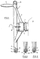
- the present invention relates to a manual handwheel of the disengageable type for a machine tool and more particularly for a machine having rapid automatic displacement members.
- the flywheel is capable, at the end of the stroke in automatic advance, of reaching a high rotational speed which may, on some of them, correspond approximately to the rotation of the axis transmitting the movement.
- the object of the present invention is therefore to eliminate the aforementioned drawbacks by proposing a flywheel that is both handy and safe, said flywheel of the type comprising a body forming its outer periphery linked to a hub mounted disengageable on an axis transmitting the movement of a rapid displacement member of a machine tool being characterized in that the aforementioned body (3) comprises movable weights (17) having the function of canceling its drive in rotation due to the axis-hub friction.
- the aforementioned body has a generally hollow toric shape whose volume is partially filled with weights.
- the body is obtained from a solid flywheel taken up in machining and on which a closing casing is fixed.
- FIG. 1 represents a manual flywheel 1 according to the invention provided with an operating handle 2 and constituted by a body 3 forming its outer periphery of generally toric shape connected by means of spokes 4 to a hub 5 mounted, as known per se , disengageable on a substantially horizontal axis 7 transmitting the movement of a member 9 for rapid automatic movement of a machine tool such as a milling machine for example (not shown).
- a machine tool such as a milling machine for example (not shown).
- the solid body 3 has been taken up in machining so as to dig therein, preferably on the inner side, a circular groove 11 which cooperates with an attached casing 13 fixed, by means of screws 15 for example, on said body to produce a hollow volume and closed 16, of generally substantially toroidal shape partially filled with weights or balls 17 capable of moving freely inside said volume.
- FIG. 2 represents an alternative embodiment of the body 3 which is constituted by a torus which comes directly from the foundry and in which is provided a hole 19 for the passage of the weights or balls 17, hole which is then plugged by means of a curable paste 20 in particular.
- FIG. 3 represents another variant which differs from the previous one by the use of a raceway for the balls 17 constituted by a tube 21 which lines the inside of the torus with a hole 19 in the body 3 , 1 set / being obtained by a molding process in which the tube is inserted, before casting, in the mold intended to produce said flywheel.
- the weights or balls are intended to move freely inside the body 3 and therefore have a diameter less than that of the volume section or the aforementioned torus; moreover, the weights or balls occupy only part of the hollow volume of the body 3.
- the volume occupied by the elements 17 represents approximately 10% of the hollow volume defined above and that the ratio between the diameter of the balls and that of the section of the torus is lower. at 6/15.
Landscapes
- Engineering & Computer Science (AREA)
- Mechanical Engineering (AREA)
- Physics & Mathematics (AREA)
- General Engineering & Computer Science (AREA)
- General Physics & Mathematics (AREA)
- Automation & Control Theory (AREA)
- Acoustics & Sound (AREA)
- Aviation & Aerospace Engineering (AREA)
- Steering-Linkage Mechanisms And Four-Wheel Steering (AREA)
- Toys (AREA)
- Mechanical Operated Clutches (AREA)
Applications Claiming Priority (2)
| Application Number | Priority Date | Filing Date | Title |
|---|---|---|---|
| FR8117460 | 1981-09-16 | ||
| FR8117460A FR2512720A1 (fr) | 1981-09-16 | 1981-09-16 | Volant de manoeuvre manuel du type debrayable pour machine-outil |
Publications (1)
| Publication Number | Publication Date |
|---|---|
| EP0074884A1 true EP0074884A1 (de) | 1983-03-23 |
Family
ID=9262181
Family Applications (1)
| Application Number | Title | Priority Date | Filing Date |
|---|---|---|---|
| EP82401620A Withdrawn EP0074884A1 (de) | 1981-09-16 | 1982-09-02 | Handrad mit Kupplung für Werkzeugmaschinen |
Country Status (4)
| Country | Link |
|---|---|
| EP (1) | EP0074884A1 (de) |
| JP (1) | JPS5857542A (de) |
| ES (1) | ES274742Y (de) |
| FR (1) | FR2512720A1 (de) |
Cited By (2)
| Publication number | Priority date | Publication date | Assignee | Title |
|---|---|---|---|---|
| EP0911091A3 (de) * | 1997-10-21 | 2002-06-12 | Ykk Corporation | Drahtwalzvorrichtung |
| TWI579102B (zh) * | 2014-06-06 | 2017-04-21 | Control of the mechanical control of the clutch mechanism |
Citations (5)
| Publication number | Priority date | Publication date | Assignee | Title |
|---|---|---|---|---|
| DE977086C (de) * | 1954-03-20 | 1965-01-28 | Kloeckner Humboldt Deutz Ag | Handrad zum Betaetigen von Bremsen, Entladeklappen und dergleichen bei Schienenfahrzeugen |
| US3548508A (en) * | 1968-11-14 | 1970-12-22 | Richard F Olson | Center locater device |
| GB1303813A (de) * | 1969-05-22 | 1973-01-24 | ||
| DE2427332A1 (de) * | 1974-06-06 | 1975-12-18 | Heinrich Hermanus | Transparenter hohlkoerper mit innerem beschlagschutz |
| US3990535A (en) * | 1975-09-11 | 1976-11-09 | Bruce Jimmie R | Vibration damping device for levers |
Family Cites Families (1)
| Publication number | Priority date | Publication date | Assignee | Title |
|---|---|---|---|---|
| JPS5211147A (en) * | 1975-07-18 | 1977-01-27 | Nippon Handa Kogyo | Automatic soldering device |
-
1981
- 1981-09-16 FR FR8117460A patent/FR2512720A1/fr active Granted
-
1982
- 1982-08-20 ES ES1982274742U patent/ES274742Y/es not_active Expired
- 1982-09-02 EP EP82401620A patent/EP0074884A1/de not_active Withdrawn
- 1982-09-13 JP JP15825882A patent/JPS5857542A/ja active Pending
Patent Citations (5)
| Publication number | Priority date | Publication date | Assignee | Title |
|---|---|---|---|---|
| DE977086C (de) * | 1954-03-20 | 1965-01-28 | Kloeckner Humboldt Deutz Ag | Handrad zum Betaetigen von Bremsen, Entladeklappen und dergleichen bei Schienenfahrzeugen |
| US3548508A (en) * | 1968-11-14 | 1970-12-22 | Richard F Olson | Center locater device |
| GB1303813A (de) * | 1969-05-22 | 1973-01-24 | ||
| DE2427332A1 (de) * | 1974-06-06 | 1975-12-18 | Heinrich Hermanus | Transparenter hohlkoerper mit innerem beschlagschutz |
| US3990535A (en) * | 1975-09-11 | 1976-11-09 | Bruce Jimmie R | Vibration damping device for levers |
Cited By (2)
| Publication number | Priority date | Publication date | Assignee | Title |
|---|---|---|---|---|
| EP0911091A3 (de) * | 1997-10-21 | 2002-06-12 | Ykk Corporation | Drahtwalzvorrichtung |
| TWI579102B (zh) * | 2014-06-06 | 2017-04-21 | Control of the mechanical control of the clutch mechanism |
Also Published As
| Publication number | Publication date |
|---|---|
| ES274742Y (es) | 1984-08-16 |
| JPS5857542A (ja) | 1983-04-05 |
| FR2512720B1 (de) | 1984-03-16 |
| FR2512720A1 (fr) | 1983-03-18 |
| ES274742U (es) | 1984-01-16 |
Similar Documents
| Publication | Publication Date | Title |
|---|---|---|
| EP0712667B1 (de) | Zentrifuge mit abnehmbarem Rotor und einer Einrichtung zur axialen Verriegelung des Rotors auf der Antriebswelle | |
| EP0497139B1 (de) | Kopf für Handstück und Handstück insbesondere für die Zahnchirurgie | |
| FR2573303A1 (fr) | Mandrin a levier pour piece a main dentaire | |
| FR2552838A1 (fr) | Mecanisme planetaire a billes reglable de facon continue | |
| FR2621964A1 (fr) | Mecanisme de crabotage | |
| FR2499448A1 (fr) | Tete de coupe pour appareil de coupe a lame non protegee | |
| EP0004230B1 (de) | Vorrichtung zum Betätigen und Kontrollieren der Neigung eines Fahrzeugaufbaus | |
| FR2740940A1 (fr) | Transmission pour tondeuse a gazon autopropulsee | |
| EP1751445B9 (de) | Kupplung zwischen einer rotationsausgangsantriebswelle für ein schneidgerät, rotationsquerschneider und schneidvorrichtung mit dieser kupplung | |
| FR2465871A1 (fr) | Marteau perforateur | |
| FR2479048A1 (fr) | Tourelle porte-outils a corps revolver | |
| EP0074884A1 (de) | Handrad mit Kupplung für Werkzeugmaschinen | |
| FR2546454A1 (fr) | Vehicule de travail autopropulse | |
| FR2683285A1 (fr) | Mecanisme a roue libre pour vehicules a traction integrale. | |
| FR2580360A1 (fr) | Machine agricole de type a operateur marchant a pied, equipee d'un systeme de transmission muni d'un appareil de changement de vitesses progressif a friction de type a disques | |
| FR2552696A1 (fr) | Marteau perforateur | |
| FR2727886A1 (fr) | Dispositif de faconnage de tubes | |
| FR2946405A1 (fr) | Dispositif d'inversion de sens de marche d'un engin roulant automoteur | |
| FR2538066A1 (fr) | Vanne et ponceuse a main incorporant une telle vanne | |
| FR2681275A3 (en) | Apparatus for changing a cutting tool built into a machine | |
| EP0278898A1 (de) | Drehendes Futter für Schneidpost | |
| FR2694796A1 (fr) | Embrayage visqueux. | |
| EP0081160B1 (de) | Verlängerungsvorrichtung für die Vorgelegewelle eines Schaltgetriebes für Kraftfahrzeuge | |
| FR2979557A1 (fr) | Dispositif de reglage fin d'une machine-outil | |
| FR2700131A3 (fr) | Ponceuse excentrique à disque comportant un frein de disque. |
Legal Events
| Date | Code | Title | Description |
|---|---|---|---|
| PUAI | Public reference made under article 153(3) epc to a published international application that has entered the european phase |
Free format text: ORIGINAL CODE: 0009012 |
|
| 17P | Request for examination filed |
Effective date: 19820906 |
|
| AK | Designated contracting states |
Designated state(s): AT DE GB IT SE |
|
| STAA | Information on the status of an ep patent application or granted ep patent |
Free format text: STATUS: THE APPLICATION IS DEEMED TO BE WITHDRAWN |
|
| 18D | Application deemed to be withdrawn |
Effective date: 19850522 |
|
| RIN1 | Information on inventor provided before grant (corrected) |
Inventor name: CABROL, ROBERT |