EP0074875A2 - Heavy-duty rocker arm - Google Patents
Heavy-duty rocker arm Download PDFInfo
- Publication number
- EP0074875A2 EP0074875A2 EP82401592A EP82401592A EP0074875A2 EP 0074875 A2 EP0074875 A2 EP 0074875A2 EP 82401592 A EP82401592 A EP 82401592A EP 82401592 A EP82401592 A EP 82401592A EP 0074875 A2 EP0074875 A2 EP 0074875A2
- Authority
- EP
- European Patent Office
- Prior art keywords
- rocker arm
- layers
- wide
- portions
- openings
- Prior art date
- Legal status (The legal status is an assumption and is not a legal conclusion. Google has not performed a legal analysis and makes no representation as to the accuracy of the status listed.)
- Granted
Links
Images
Classifications
-
- F—MECHANICAL ENGINEERING; LIGHTING; HEATING; WEAPONS; BLASTING
- F01—MACHINES OR ENGINES IN GENERAL; ENGINE PLANTS IN GENERAL; STEAM ENGINES
- F01L—CYCLICALLY OPERATING VALVES FOR MACHINES OR ENGINES
- F01L1/00—Valve-gear or valve arrangements, e.g. lift-valve gear
- F01L1/12—Transmitting gear between valve drive and valve
- F01L1/18—Rocking arms or levers
- F01L1/181—Centre pivot rocking arms
-
- F—MECHANICAL ENGINEERING; LIGHTING; HEATING; WEAPONS; BLASTING
- F02—COMBUSTION ENGINES; HOT-GAS OR COMBUSTION-PRODUCT ENGINE PLANTS
- F02B—INTERNAL-COMBUSTION PISTON ENGINES; COMBUSTION ENGINES IN GENERAL
- F02B3/00—Engines characterised by air compression and subsequent fuel addition
- F02B3/06—Engines characterised by air compression and subsequent fuel addition with compression ignition
Definitions
- This invention relates to a heavy-duty rocker arm formed of stamped metal sheets.
- the present invention provides a stamped rocker arm basically which consists of two stamped metal pieces or sheets, each having two wide portions joined by a narrow web portion.
- the wide portions are turned back around the web portions and are located in contiguous relationship to form the main body portion of the rocker arm.
- the web portions thereby form loops which carry push rod screws and stem pads.
- the wide portions of one of the metal sheets have inner surfaces in contiguous relationship with the wide portions of the other metal sheet having inner surfaces in contiguous relationship with the outer surfaces of the first sheet.
- the four layers of metal are affixed together, as by rivets, with the four layers providing the required strength for the main body portion of the rocker arm without excessive weight in outer portions.
- the wide portions of the second sheet can be shaped to extend closer to the looped end portion of the first sheet, if desired, when greater strength is required of the outer portions of the rocker arm.
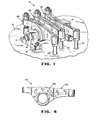
- an overall rocker arm assembly for a diesel engine or the like is indicated at 10.
- the assembly is located above a cylinder head 12 of the engine, on which are located two bearing blocks 14 carrying a rocker arm shaft 16 into which oil can be supplied from a suitable passage 18.
- a center rocker arm 20 mounted on the shaft operates a fuel injector through a stem 22 while outer rocker arms 24 and 26 operate supply and exhaust valves of the engine cylinder therebelow through valve stems 28 and 30.
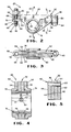
- the rocker arm 20 for the injector is shown more fully in Figs. 2-5.
- the rocker arm includes a first stamped metal piece or sheet 32 of generally bow-tie shape, when flat. It includes two wide end portions or layers 34 and 36 connected by a narrow web portion 38.
- the first piece 32 is doubled back with the inner surfaces of the wide portions 34 and 36 in contiguous relationship, with the web portion 38 sized or drilled to form a loop 40.
- the inner surfaces of the wide portions 34 and 36 have matching grooves 42 and 44 forming an oil passage 46 communicating with short, vertical grooves forming a short end or vertical passage 48 adjacent the loop 40.
- An upper portion of the web portion 38 is staked to close off the loop 40 above the passage 48.
- the inner surfaces of the wide portions 34 and 38 also have matching grooves 50 and 52 forming an oil passage 54 extending in the oppositive direction from the passage 46.
- lower portions of the wide portions 34 and 36 have intermediate circular openings 56 and 58 through which the rocker arm shaft 16 will extend.
- the rocker arm 20 also includes a second stamped metal piece or sheet 60 which is also of generally bow-tie shape, when flat. It includes two wide end portions or layers 62 and 64 connected by a narrow web portion 66.
- the second piece 60 is doubled back to form a loop 68 with the inner surfaces of the wide portions 62 and 64 being contiguous' with the outer surfaces of the wide portions 34 and 36 of the first sheet 32.
- the loop 68 cooperates with narrower ends of the wide portions 34 and 36, as shown in Fig. 3, to form an opening which is drilled and tapped to produce a threaded bore 70.
- An engageable member or screw 86 has a threaded shank 88 threadably engaged in the threaded bore 70 and has a lower rounded end 90 engageable with the upper end of a push rod.
- the screw 86 is of a known design, having an annular groove 92 with radially-extending passages 94 communicating with a central passage 96 for supplying oil from the passage 54 to the upper P n.d of the push rod.
- the upper end of the screw 86 can have a hexagonal recess or the like for receiving a tool to adjust the screw up and down relative to the rocker arm, with a jam nut 98 holding the screw in position, when properly adjusted.
- the rocker arm 24 for the valve stem 28 is shown in Fig. 6 without the engageable members assembled in the ends.
- the rocker arm 24 also includes a first stamped metal piece or sheet -102 and a second stamped metal piece or sheet 104.
- the basic difference between the rocker arms 20 and 24 from the standpoint of the instant invention is that the wide portions of the second metal piece 104 terminate near the rocker arm shaft openings rather than extend toward the outer end of the first stamped metal piece 102. This is because the force encountered at the outer end, near the valve stem 28 or 30, is not as high as that required for the injector stem 22. Consequently, the wide portions of the second stamped metal piece 104 can accordingly be shortened to reduce the weight of the overall rocker arm. Hence, this construction can be tailored to fit the strength and rigidity requirements of the particular rocker arm to maintain weight at a minimum.
Landscapes
- Engineering & Computer Science (AREA)
- Mechanical Engineering (AREA)
- General Engineering & Computer Science (AREA)
- Valve-Gear Or Valve Arrangements (AREA)
- Fuel-Injection Apparatus (AREA)
Abstract
Description
- This invention relates to a heavy-duty rocker arm formed of stamped metal sheets.
- Heavy-duty rocker arms, particularly for diesel engines and other larger engines, are commonly cast or forged to provide the high strength which is required. In particular, the cast or forged construction has been needed in order to obtain sufficient strength in the main body portion of the rocker arm below the rocker arm shaft, where space is limited. Greater strength is required in that area in diesel engines, for example, because of the higher cylinder pressures and other forces encountered in comparison with smaller gasoline engines.
- The present invention provides a stamped rocker arm basically which consists of two stamped metal pieces or sheets, each having two wide portions joined by a narrow web portion. The wide portions are turned back around the web portions and are located in contiguous relationship to form the main body portion of the rocker arm. The web portions thereby form loops which carry push rod screws and stem pads. The wide portions of one of the metal sheets have inner surfaces in contiguous relationship with the wide portions of the other metal sheet having inner surfaces in contiguous relationship with the outer surfaces of the first sheet. The four layers of metal are affixed together, as by rivets, with the four layers providing the required strength for the main body portion of the rocker arm without excessive weight in outer portions. Further, the wide portions of the second sheet can be shaped to extend closer to the looped end portion of the first sheet, if desired, when greater strength is required of the outer portions of the rocker arm.
- It is, therefore, a principal object of the invention to provide a stamped rocker arm construction, particularly for heavy-duty applications, such as for diesel engines which has high strength in the area below the shaft on which the rocker arm is mounted and which is lighter in weight.
- Other features and advantages of the invention will be apparent from the following description thereof, which refers to the accompanying drawings wherein :
- - Figure 1 is a somewhat schematic view in perspective of a rocker arm assembly employing rocker arms embodying the invention ;
- - Figure 2 is a side view in -elevation; with parts broken away and with parts in section, of one of the rocker arms of Figure 1 ;
- - Figure 3 is a top view of the rocker arm of Figure 2 ;
- - Figure 4 is an enlarged view in transverse cross section taken along the line 4-4 of Figure 2.;
- - Figure 5 is an enlarged view in transverse cross-section taken along the line 5-5 of Figure 2 ; and
- - Figure 6 is a side view in elevation of another rocker arm of Figure 1, with certain components omitted.
- Referring to the drawings, and more particularly to Figure 1 an overall rocker arm assembly for a diesel engine or the like is indicated at 10. The assembly is located above a
cylinder head 12 of the engine, on which are located two bearingblocks 14 carrying arocker arm shaft 16 into which oil can be supplied from asuitable passage 18. Acenter rocker arm 20 mounted on the shaft operates a fuel injector through astem 22 whileouter rocker arms valve stems - The
rocker arm 20 for the injector is shown more fully in Figs. 2-5. The rocker arm includes a first stamped metal piece orsheet 32 of generally bow-tie shape, when flat. It includes two wide end portions orlayers narrow web portion 38. Thefirst piece 32 is doubled back with the inner surfaces of thewide portions web portion 38 sized or drilled to form aloop 40. The inner surfaces of thewide portions grooves oil passage 46 communicating with short, vertical grooves forming a short end orvertical passage 48 adjacent theloop 40. An upper portion of theweb portion 38 is staked to close off theloop 40 above thepassage 48. The inner surfaces of thewide portions grooves oil passage 54 extending in the oppositive direction from thepassage 46. In addition, lower portions of thewide portions circular openings rocker arm shaft 16 will extend. - The
rocker arm 20 also includes a second stamped metal piece orsheet 60 which is also of generally bow-tie shape, when flat. It includes two wide end portions orlayers narrow web portion 66. Thesecond piece 60 is doubled back to form aloop 68 with the inner surfaces of thewide portions wide portions first sheet 32. Theloop 68 cooperates with narrower ends of thewide portions bore 70. Thewide portions circular flanges circular opening wide portions first piece 32. These receive a bronze bushing orsleeve 76 which is force fit and pivotally supports therocker arm 20 on theshaft 16. The bushing orsleeve 76 has an opening 78 (Fig. 2) communicating with theoil passage 46 and anopening 80 along with a groove 82 (Fig. 5) communicating with theoil passage 54. These openings and groove receive oil through therocker arm shaft 16 having longitudinally-located openings therein and, in turn supply oil to theloop 40 and the threadedbore 70. Theloop 40 receives an engageable member orpad 84 which has ashank 85 force fit in theloop 40 and oil from thepassages pad 84 which engages the upper end of theinjector stem 22. - An engageable member or
screw 86 has a threadedshank 88 threadably engaged in the threadedbore 70 and has a lowerrounded end 90 engageable with the upper end of a push rod. Thescrew 86 is of a known design, having anannular groove 92 with radially-extendingpassages 94 communicating with acentral passage 96 for supplying oil from thepassage 54 to the upper Pn.d of the push rod. The upper end of thescrew 86 can have a hexagonal recess or the like for receiving a tool to adjust the screw up and down relative to the rocker arm, with ajam nut 98 holding the screw in position, when properly adjusted. - The
wide portions pieces rivets 100 are employed for this purpose. Because high pressures and high strength are required at the end of therocker arm 20 having theinjector stem pad 84, thewide portions piece 60 extend near the loop end of thepiece 32 for additional strength and stiffness. When the rocker arm is otherwise complete, it is brazed to provide additional strength and also to seal the openings on the oil passages. This is done before the components are assembled. - The
rocker arm 24 for thevalve stem 28 is shown in Fig. 6 without the engageable members assembled in the ends. Therocker arm 24 also includes a first stamped metal piece or sheet -102 and a second stamped metal piece orsheet 104. The basic difference between therocker arms second metal piece 104 terminate near the rocker arm shaft openings rather than extend toward the outer end of the first stampedmetal piece 102. This is because the force encountered at the outer end, near thevalve stem injector stem 22. Consequently, the wide portions of the second stampedmetal piece 104 can accordingly be shortened to reduce the weight of the overall rocker arm. Hence, this construction can be tailored to fit the strength and rigidity requirements of the particular rocker arm to maintain weight at a minimum.
Claims (1)
- A heavy-duty rocker arm (20) characterized in that said rocker arm (20) comprises a first stamped sheet of metal (32) including two wide first layers (34, 36) having contiguous inner surfaces and having aligned first openings (56, 58) for receiving a rocker arm shaft (16), said wide first layers (34, 36) being joined by a first narrow loop portion (40) at common ends of said wide layers (34, 36), ends of said layers on the other side of said intermediate openings terminating in adjacent locations, a second stamped sheet of metal (60) including two wide additional layers (62, 64) having surfaces contiguous with outer surfaces of said first layers (34, 36), said additional layers having second openings (72, 74) aligned with the first openings (56, 58) and joined at common ends by an additional loop portion (68) on the side of said first and second openings (56, 58, 72, 74) opposite said first loop portion (40) and means (100) affixing said wide first layers (34, 36) and said wide additional layers (62, 64) together.
Applications Claiming Priority (2)
| Application Number | Priority Date | Filing Date | Title |
|---|---|---|---|
| US29938381A | 1981-09-04 | 1981-09-04 | |
| US299383 | 1994-09-01 |
Publications (3)
| Publication Number | Publication Date |
|---|---|
| EP0074875A2 true EP0074875A2 (en) | 1983-03-23 |
| EP0074875A3 EP0074875A3 (en) | 1983-06-15 |
| EP0074875B1 EP0074875B1 (en) | 1985-10-23 |
Family
ID=23154544
Family Applications (1)
| Application Number | Title | Priority Date | Filing Date |
|---|---|---|---|
| EP19820401592 Expired EP0074875B1 (en) | 1981-09-04 | 1982-08-27 | Heavy-duty rocker arm |
Country Status (3)
| Country | Link |
|---|---|
| EP (1) | EP0074875B1 (en) |
| JP (1) | JPS5864805U (en) |
| DE (1) | DE3267044D1 (en) |
Cited By (5)
| Publication number | Priority date | Publication date | Assignee | Title |
|---|---|---|---|---|
| DE4433278A1 (en) * | 1994-09-19 | 1996-03-28 | Motoren Werke Mannheim Ag | IC engine valve gear lubrication |
| US6516766B2 (en) * | 1997-04-23 | 2003-02-11 | Koyo Seiko Co., Ltd. | Rocker arm |
| EP1420147A1 (en) * | 2002-11-12 | 2004-05-19 | Schätti AG | Workpiece comprising interconnected lamination stacks |
| DE102004052998A1 (en) * | 2004-11-03 | 2006-05-04 | Deutz Ag | Tilting or pulling lever with ball pressure piece for controlling valves has stepped or blind boring with support surface |
| WO2015154762A1 (en) * | 2014-04-10 | 2015-10-15 | Schaeffler Technologies AG & Co. KG | Sheet-metal rocker arm |
Families Citing this family (2)
| Publication number | Priority date | Publication date | Assignee | Title |
|---|---|---|---|---|
| JP2585000B2 (en) * | 1987-07-01 | 1997-02-26 | ヤンマーディーゼル株式会社 | Valve arm support structure for intake and exhaust valves of diesel engines |
| CN103850738A (en) * | 2014-03-28 | 2014-06-11 | 浙江龙虎锻造有限公司 | Valve rocker arm shaft |
Citations (3)
| Publication number | Priority date | Publication date | Assignee | Title |
|---|---|---|---|---|
| US2578638A (en) * | 1944-07-19 | 1951-12-11 | John R Winter Sr | Rocker arm |
| US2811959A (en) * | 1954-12-28 | 1957-11-05 | Gen Motors Corp | Valve actuating mechanism |
| US3222950A (en) * | 1964-06-03 | 1965-12-14 | Jr John R Winter | Rocker arm for internal-combustion engines |
-
1982
- 1982-08-27 EP EP19820401592 patent/EP0074875B1/en not_active Expired
- 1982-08-27 DE DE8282401592T patent/DE3267044D1/en not_active Expired
- 1982-09-03 JP JP13318582U patent/JPS5864805U/en active Granted
Patent Citations (3)
| Publication number | Priority date | Publication date | Assignee | Title |
|---|---|---|---|---|
| US2578638A (en) * | 1944-07-19 | 1951-12-11 | John R Winter Sr | Rocker arm |
| US2811959A (en) * | 1954-12-28 | 1957-11-05 | Gen Motors Corp | Valve actuating mechanism |
| US3222950A (en) * | 1964-06-03 | 1965-12-14 | Jr John R Winter | Rocker arm for internal-combustion engines |
Cited By (6)
| Publication number | Priority date | Publication date | Assignee | Title |
|---|---|---|---|---|
| DE4433278A1 (en) * | 1994-09-19 | 1996-03-28 | Motoren Werke Mannheim Ag | IC engine valve gear lubrication |
| DE4433278B4 (en) * | 1994-09-19 | 2004-05-27 | Deutz Ag | Lubrication of the valve train |
| US6516766B2 (en) * | 1997-04-23 | 2003-02-11 | Koyo Seiko Co., Ltd. | Rocker arm |
| EP1420147A1 (en) * | 2002-11-12 | 2004-05-19 | Schätti AG | Workpiece comprising interconnected lamination stacks |
| DE102004052998A1 (en) * | 2004-11-03 | 2006-05-04 | Deutz Ag | Tilting or pulling lever with ball pressure piece for controlling valves has stepped or blind boring with support surface |
| WO2015154762A1 (en) * | 2014-04-10 | 2015-10-15 | Schaeffler Technologies AG & Co. KG | Sheet-metal rocker arm |
Also Published As
| Publication number | Publication date |
|---|---|
| EP0074875B1 (en) | 1985-10-23 |
| JPS5864805U (en) | 1983-05-02 |
| JPH0227180Y2 (en) | 1990-07-23 |
| DE3267044D1 (en) | 1985-11-28 |
| EP0074875A3 (en) | 1983-06-15 |
Similar Documents
| Publication | Publication Date | Title |
|---|---|---|
| EP0785340B1 (en) | A rocker arm assembly for an internal combustion engine | |
| US5289758A (en) | Pin plugs for use in a piston assembly | |
| US5566658A (en) | Clamping load distributor and top stop for a fuel injector | |
| US5676098A (en) | Mechanical direct-acting tappet with roller follower | |
| CA2103771C (en) | Rocker arm of the cam-follower type for operating two valves | |
| US4674453A (en) | Rocker arm and method of forming the same | |
| KR20050084180A (en) | Multipart cooled piston for an internal combustion engine | |
| EP0767291A1 (en) | Light weight cam follower | |
| EP0074875A2 (en) | Heavy-duty rocker arm | |
| JPH08510813A (en) | Piston assembly with load-distributed central fixed wrist pin | |
| US5251587A (en) | Valve lifter for engine | |
| US5445119A (en) | Tappet and shim assembly for internal combustion engine | |
| US5188068A (en) | Roller tappet | |
| EP0342383B1 (en) | Adjustable lash valve train for overhead valve engine | |
| US3626469A (en) | Valve gear | |
| EP1024253B1 (en) | Electromagnetic valve actuating apparatus for internal combustion engine | |
| US5560265A (en) | Rocker arm mounting stud | |
| US3963004A (en) | Two-piece valve bridge | |
| US5577470A (en) | Valve system for internal combustion engine | |
| CA1275016A (en) | Engine rocker arm assembly | |
| US5492085A (en) | Supported pushrod for internal combustion engines | |
| US5410995A (en) | Valve crosshead assembly with wear-reducing contact pad | |
| US5983848A (en) | Finger follower | |
| EP0923090A1 (en) | Electromagnetic actuator with detached lower collar to align with cylinder head bore | |
| GB2296531A (en) | Fuel injector clamping |
Legal Events
| Date | Code | Title | Description |
|---|---|---|---|
| PUAI | Public reference made under article 153(3) epc to a published international application that has entered the european phase |
Free format text: ORIGINAL CODE: 0009012 |
|
| 17P | Request for examination filed |
Effective date: 19820908 |
|
| AK | Designated contracting states |
Designated state(s): DE FR GB |
|
| PUAL | Search report despatched |
Free format text: ORIGINAL CODE: 0009013 |
|
| AK | Designated contracting states |
Designated state(s): DE FR GB |
|
| GRAA | (expected) grant |
Free format text: ORIGINAL CODE: 0009210 |
|
| AK | Designated contracting states |
Designated state(s): DE FR GB |
|
| REF | Corresponds to: |
Ref document number: 3267044 Country of ref document: DE Date of ref document: 19851128 |
|
| ET | Fr: translation filed | ||
| PLBE | No opposition filed within time limit |
Free format text: ORIGINAL CODE: 0009261 |
|
| STAA | Information on the status of an ep patent application or granted ep patent |
Free format text: STATUS: NO OPPOSITION FILED WITHIN TIME LIMIT |
|
| 26N | No opposition filed | ||
| PG25 | Lapsed in a contracting state [announced via postgrant information from national office to epo] |
Ref country code: FR Free format text: LAPSE BECAUSE OF NON-PAYMENT OF DUE FEES Effective date: 19880429 |
|
| REG | Reference to a national code |
Ref country code: FR Ref legal event code: ST |
|
| PG25 | Lapsed in a contracting state [announced via postgrant information from national office to epo] |
Ref country code: GB Free format text: LAPSE BECAUSE OF NON-PAYMENT OF DUE FEES Effective date: 19880827 |
|
| PG25 | Lapsed in a contracting state [announced via postgrant information from national office to epo] |
Ref country code: DE Effective date: 19890503 |
|
| GBPC | Gb: european patent ceased through non-payment of renewal fee |