EP0074531A1 - Fuel injection device - Google Patents
Fuel injection device Download PDFInfo
- Publication number
- EP0074531A1 EP0074531A1 EP82107780A EP82107780A EP0074531A1 EP 0074531 A1 EP0074531 A1 EP 0074531A1 EP 82107780 A EP82107780 A EP 82107780A EP 82107780 A EP82107780 A EP 82107780A EP 0074531 A1 EP0074531 A1 EP 0074531A1
- Authority
- EP
- European Patent Office
- Prior art keywords
- fuel
- internal combustion
- combustion engine
- compressor
- air
- Prior art date
- Legal status (The legal status is an assumption and is not a legal conclusion. Google has not performed a legal analysis and makes no representation as to the accuracy of the status listed.)
- Withdrawn
Links
Images
Classifications
-
- F—MECHANICAL ENGINEERING; LIGHTING; HEATING; WEAPONS; BLASTING
- F02—COMBUSTION ENGINES; HOT-GAS OR COMBUSTION-PRODUCT ENGINE PLANTS
- F02M—SUPPLYING COMBUSTION ENGINES IN GENERAL WITH COMBUSTIBLE MIXTURES OR CONSTITUENTS THEREOF
- F02M69/00—Low-pressure fuel-injection apparatus ; Apparatus with both continuous and intermittent injection; Apparatus injecting different types of fuel
- F02M69/04—Injectors peculiar thereto
- F02M69/042—Positioning of injectors with respect to engine, e.g. in the air intake conduit
-
- F—MECHANICAL ENGINEERING; LIGHTING; HEATING; WEAPONS; BLASTING
- F02—COMBUSTION ENGINES; HOT-GAS OR COMBUSTION-PRODUCT ENGINE PLANTS
- F02B—INTERNAL-COMBUSTION PISTON ENGINES; COMBUSTION ENGINES IN GENERAL
- F02B29/00—Engines characterised by provision for charging or scavenging not provided for in groups F02B25/00, F02B27/00 or F02B33/00 - F02B39/00; Details thereof
- F02B29/04—Cooling of air intake supply
- F02B29/0481—Intake air cooling by means others than heat exchangers, e.g. by rotating drum regenerators, cooling by expansion or by electrical means
-
- F—MECHANICAL ENGINEERING; LIGHTING; HEATING; WEAPONS; BLASTING
- F02—COMBUSTION ENGINES; HOT-GAS OR COMBUSTION-PRODUCT ENGINE PLANTS
- F02M—SUPPLYING COMBUSTION ENGINES IN GENERAL WITH COMBUSTIBLE MIXTURES OR CONSTITUENTS THEREOF
- F02M69/00—Low-pressure fuel-injection apparatus ; Apparatus with both continuous and intermittent injection; Apparatus injecting different types of fuel
- F02M69/04—Injectors peculiar thereto
- F02M69/042—Positioning of injectors with respect to engine, e.g. in the air intake conduit
- F02M69/044—Positioning of injectors with respect to engine, e.g. in the air intake conduit for injecting into the intake conduit downstream of an air throttle valve
-
- Y—GENERAL TAGGING OF NEW TECHNOLOGICAL DEVELOPMENTS; GENERAL TAGGING OF CROSS-SECTIONAL TECHNOLOGIES SPANNING OVER SEVERAL SECTIONS OF THE IPC; TECHNICAL SUBJECTS COVERED BY FORMER USPC CROSS-REFERENCE ART COLLECTIONS [XRACs] AND DIGESTS
- Y02—TECHNOLOGIES OR APPLICATIONS FOR MITIGATION OR ADAPTATION AGAINST CLIMATE CHANGE
- Y02T—CLIMATE CHANGE MITIGATION TECHNOLOGIES RELATED TO TRANSPORTATION
- Y02T10/00—Road transport of goods or passengers
- Y02T10/10—Internal combustion engine [ICE] based vehicles
- Y02T10/12—Improving ICE efficiencies
Definitions
- the invention is based on a fuel injection system according to the preamble of the main claim.
- a fuel injection system is already known in which the injection takes place downstream of the turbocharger. This has the disadvantage that the air temperatures before entering the cylinders of the internal combustion engine rise to over 100 ° C in some cases, which results in lower filling and poorer efficiency of the internal combustion engine.
- the fuel injection system according to the invention with the characterizing features of the main claim has the advantage that the fuel injected upstream of the compressor due to its energy requirement during evaporation leads to cooling of the intake air and the compressor, which in addition to an extension of the life of the compressor due to less wear higher degree of filling of the internal combustion engine and thus an increase in performance is achieved. Further advantages are an earlier ignition timing with the result of lower fuel consumption and better efficiency, which reduces harmful components in the exhaust gas.
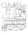
- the combustion air flows through an air filter 1 into an intake manifold section 2, in which an air measuring element 3 of a known type, for example a hot wire air mass meter or a damper air volume meter, is arranged.
- an air measuring element 3 of a known type, for example a hot wire air mass meter or a damper air volume meter
- a compressor 5 for example a turbocharger of known type, which compresses the air quantity drawn in by an internal combustion engine 4
- individual intake pipes 8 branch off from the intake pipe section 6 and lead to the individual cylinders of the internal combustion engine 4.
- the illustrated internal combustion engine 4 is intended to be a 6-cylinder internal combustion engine.
- At 10 is one Exhaust gas line, which leads to an exhaust gas turbine 11, which is rigidly coupled to the compressor 5 and is driven by the heated and highly compressed exhaust gas.
- a bypass valve 12 is used to open when the maximum permissible boost pressure in the intake manifold section 6 is reached and to allow part of the exhaust gas to flow past the exhaust gas turbine 11.
- a main injection valve 14 is arranged on each individual intake manifold 8, via which fuel can be injected immediately before the intake valve of each cylinder.
- the main injection valves 14 are connected to a fuel distributor line 15, into which fuel is conveyed from a fuel tank 18 by a fuel pump 17 driven by an electric motor 16.
- a pressure control valve 19 ensures a constant fuel pressure in the fuel rail 15.
- the exemplary embodiment of a fuel injection system shown, for example, is to be an electronic fuel injection system with main injection valves 14 designed as electromagnetic valves.
- the main injection valves 14 are activated via a control line 20 by an electronic control unit 21 Known type depending on the operating parameters of the internal combustion engine such as speed 22, air volume 23, throttle valve position 24, temperature 25 and others.
- an auxiliary injection valve 27 is therefore arranged upstream of the compressor 5 on the intake manifold section 2 and is connected to the fuel rail 15 via a branch line 28.
- Evaporation of the fuel injected via the additional injection valve 27 upstream of the compressor 5 removes heat from the intake air, which not only reduces the compressor temperature, but also reduces the temperature of the air supplied to the cylinders of the internal combustion engine 4, which results in the degree of filling of the individual cylinders increases, which results in an increase in performance of the internal combustion engine. This also results in an earlier ignition timing and better efficiency, which reduces fuel consumption and the proportion of toxic exhaust gas components.
- the otherwise inventive charge air cooler can be eliminated or at least reduced by the injection according to the invention via the additional injection valve 27 upstream of the compressor.
- the additional injection valve 27 can also be controlled electromagnetically by the electronic control unit 21.
- the control of the additional injection valve 27 can advantageously take place in such a way that below the operating temperature of the internal combustion engine of approximately 80 ° C. there is no injection via the additional injection valve 27, that is to say the additional injection valve is closed.
- the amount of fuel injected in each case via the main injection valves 14 should be reduced in proportion to the amount of fuel injected via the additional injection valve 27.
- the configuration according to the invention of a fuel injection system with an additional injection valve 27 for injecting fuel upstream of the compressor is not limited to use in an electronic fuel injection system. Rather, an additional injection valve can also be provided in an equivalent configuration in a mechanical fuel injection system, which injects fuel under the conditions described upstream of the compressor 5 into the intake manifold section 2, the injection quantities being reduced in a corresponding manner via the main injection valves 14.
Abstract
Description
Die Erfindung geht aus von einer Kraftstoffeinspritzanlage nach der Gattung des Hauptanspruchs. Es ist schon eine Kraftstoffeinspritzanlage bekannt, bei der die Einspritzung stromabwärts des Turboladers erfolgt. Hierbei ergibt sich der Nachteil, daß die Lufttemperaturen vor dem Eintritt in die Zylinder der Brennkraftmaschine auf zum Teil über 100 C steigen, was eine geringere Füllung und einen schlechteren Wirkungsgrad der Brennkraftmaschine zur Folge hat.The invention is based on a fuel injection system according to the preamble of the main claim. A fuel injection system is already known in which the injection takes place downstream of the turbocharger. This has the disadvantage that the air temperatures before entering the cylinders of the internal combustion engine rise to over 100 ° C in some cases, which results in lower filling and poorer efficiency of the internal combustion engine.
Die erfindungsgemäße Kraftstoffeinspritzanlage mit den kennzeichnenden Merkmalen des Hauptanspruchs hat demgegenüber den Vorteil, daß der stromaufwärts des Verdichters eingespritzte Kraftstoff infolge seines Energiebedarfes bei der Verdampfung zu einer Kühlung der angesaugten Luft und des Verdichters führt, wodurch neben einer Verlängerung der Lebensdauer des Verdichters infolge geringeren Verschleißes ein höherer Füllungsgrad der Brennkraftmaschine und damit eine Leistungssteigerung erzielt wird. Als weitere Vorteile ergeben sich ein früherer Zündzeitpunkt mit der Folge eines niederen Kraftstoffverbrauches und ein besserer Wirkungsgrad, der eine Verringerung schädlicher Bestandteile im Abgas bewirkt.The fuel injection system according to the invention with the characterizing features of the main claim has the advantage that the fuel injected upstream of the compressor due to its energy requirement during evaporation leads to cooling of the intake air and the compressor, which in addition to an extension of the life of the compressor due to less wear higher degree of filling of the internal combustion engine and thus an increase in performance is achieved. Further advantages are an earlier ignition timing with the result of lower fuel consumption and better efficiency, which reduces harmful components in the exhaust gas.
Durch die in den Unteransprüchen aufgeführten Maßnahmen sind vorteilhafte Weiterbildungen und Verbesserungen der im Hauptanspruch angegebenen Kraftstoffeinspritzanlage möglich.The measures listed in the subclaims permit advantageous developments and improvements of the fuel injection system specified in the main claim.
Ein Ausführungsbeispiel der Erfindung ist in der Zeichnung vereinfacht dargestellt und in der nachfolgenden Beschreibung näher erläutert.An embodiment of the invention is shown in simplified form in the drawing and explained in more detail in the following description.
Bei der in der Zeichnung dargestellten Kraftstoffeinspritzanlage strömt die Verbrennungsluft durch einen Luftfilter 1 in einen Saugrohrabschnitt 2, in dem ein Luftmeßorgan 3 bekannter Bauart, beispielsweise ein Hitzdrahtluftmassenmesser oder ein Stauklappenluftmengenmesser, angeordnet ist. Stromabwärts des Luftmeßorgans 3 ist ein die von einer Brennkraftmaschine 4 angesaugte Luftmenge komprimierender Verdichter 5, beispielsweise ein Turbolader bekannter Bauart angeordnet, stromabwärts dessen die komprimierte Luft in einen Saugrohrabschnitt 6 mit einer Drosselklappe 7 gelangt. Stromabwärts der Drosselklappe 7 zweigen von dem Saugrohrabschnitt 6 Einzelsaugrohre 8 ab, die zu den einzelnen Zylindern der Brennkraftmaschine 4 führen. Bei der dargestellten Brennkraftmaschine 4 soll es sich um eine 6-Zylinder-Brennkraftmaschine handeln. Mit 10 ist eine Abgasleitung bezeichnet, die zu einer Abgas-Turbine 11 .führt, die mit dem Verdichter 5 starr gekoppelt ist und durch das erhitzte und stark komprimierte Abgas angetrieben wird. Ein Bypassventil 12 dient dazu, beim Erreichen des maximal zulässigen Ladedruckes in dem Saugrohrabschnitt 6 zu öffnen und einen Teil des Abgases an der Abgas-Turbine 11 vorbeiströmen zu lassen.In the fuel injection system shown in the drawing, the combustion air flows through an
An jedem Einzelsaugrohr 8 ist ein Haupteinspritzventil 14 angeordnet, über das Kraftstoff unmittelbar vor das Einlaßventil jedes Zylinders eingespritzt werden kann. Die Haupteinspritzventile 14 stehen mit einer Kraftstoffverteilerleitung 15 in Verbindung, in die durch eine von einem Elektromotor 16 angetriebene Kraftstoffpumpe 17 Kraftstoff aus einem Kraftstoffbehälter 18 gefördert wird. Ein Druckregelventil 19 sorgt für einen konstanten Kraftstoffdruck in der Kraftstoffverteilerleitung 15. Bei dem beispielsweise dargestellten Ausführungsbeispiel einer Kraftstoffeinspritzanlage soll es sich um eine elektronische Kraftstoffeinspritzanlage handeln mit als Elektromagnetventile ausgebildeten Haupteinspritzventilen 14. Die Ansteuerung der Haupteinspritzventile 14 erfolgt über eine Ansteuerleitung 20 durch ein elektronisches Steuergerät 21 bekannter Bauart in Abhängigkeit von Betriebskenngrössen der Brennkraftmaschine wie Drehzahl 22, Luftmenge 23, Drosselklappenstellung 24, Temperatur 25 und anderen.A
Die Komprimierung der angesaugten Luft durch den Verdichter 5 führt zum Teil zu Lufttemperaturen von über 100 °C, was zu einer geringeren Füllung der Motorzylinder und zu einer Verschlechterung des Wirkungsgrades der Brennkraftmaschine einerseits führt und andererseits die Gefahr eines höheren Verschleißes des Verdichters 5 und damit einer Verringerung der Lebensdauer in sich birgt. Erfindungsgemäß ist deshalb stromaufwärts des Verdichters 5 am Saugrohrabschnitt 2 ein Zusatzeinspritzventil 27 angeordnet, das über eine Zweigleitung 28 mit der Kraftstoffverteilerleitung 15 in Verbindung steht. Durch die Verdampfung des über das Zusatzeinspritzventil 27 stromaufwärts des Verdichters 5 eingespritzten Kraftstoffes wird der angesaugten Luft Wärme entzogen, wodurch es nicht nur zu einer Verringerung der Verdichtertemperatur, sondern auch zu einer Verringerung der Temperatur der den Zylindern der Brennkraftmaschine 4 zugeführten Luft kommt, wodurch sich der Füllungsgrad der einzelnen Zylinder erhöht, was eine Leistungssteigerung der Brennkraftmaschine zur Folge hat. Daraus ergibt sich weiterhin ein früherer Zündzeitpunkt und ein besserer Wirkungsgrad, wodurch der Kraftstoffverbrauch und die Anteile giftiger Abgasbestandteile verringert werden. Außerdem kann durch die erfindungsgemäße Einspritzung über das Zusatzeinspritzventil 27 stromaufwärts des Verdichters ein sonst üblicher Ladeluftkühler entfallen oder zumindest verkleinert werden. Das Zusatzeinspritzventil 27 kann ebenfalls elektromagnetisch ausgebildet durch das elektronische Steuergerät 21 ansteuerbar sein. Dabei kann die Ansteuerung des Zusatzeinspritzventiles 27 vorteilhafterweise derart erfolgen, daß unterhalb der Betriebstemperatur der Brennkraftmaschine von ca. 80 0C keine Einspritzung über das Zusatzeinspritzventil 27 erfolgt, das Zusatzeinspritzventil also geschlossen ist. Außerdem ist es zweckmäßig in Betriebsbereichen des Leerlaufs und der unteren Teillast der Brennkraftmaschine ebenfalls eine Einspritzung über das Zusatzeinspritzventil 27 zu unterbinden. Erst bei höherer Teillast und Vollast ist die erfindungsgemäße Einspritzung von Kraftstoff über das Zusatzeinspritzventil 27 zur Kühlung der angesaugten Luftmenge und des Verdichters 5 besonders zweckmäßig, wobei die über das Zusatzeinspritzventil 27 eingespritzte Kraftstoffmenge in Abhängigkeit von der Drehzahl 22 und/oder der Last 24 erfolgen sollte. Bei Einspritzung über das Zusatzeinspritzventil 27 sollte die über die Haupteinspritzventile 14 jeweils eingespritzte Kraftstoffmenge anteilig entsprechend der über das Zusatzeinspritzventil 27 eingespritzten Kraftstoffmenge reduziert werden.The compression of the intake air by the
Die erfindungsgemäße Ausgestaltung einer Kraftstoffeinspritzanlage mit einem Zusatzeinspritzventil 27 zur Einspritzung von Kraftstoff stromaufwärts des Verdichters ist nicht beschränkt auf die Verwendung bei einer elektronischen Kraftstoffeinspritzanlage. Vielmehr kann auch in äquivalenter Ausgestaltung bei einer mechanischen Kraftstoffeinspritzanlage ein Zusatzeinspritzventil vorgesehen sein, das unter den geschilderten Bedingungen stromaufwärts des Verdichters 5 in den Saugrohrabschnitt 2 Kraftstoff einspritzt, wobei in entsprechender Weise die Einspritzmengen über die Haupteinspritzventile 14 reduziert werden.The configuration according to the invention of a fuel injection system with an
Claims (4)
Applications Claiming Priority (2)
| Application Number | Priority Date | Filing Date | Title |
|---|---|---|---|
| DE19813135791 DE3135791A1 (en) | 1981-09-10 | 1981-09-10 | FUEL INJECTION PUMP |
| DE3135791 | 1981-09-10 |
Publications (1)
| Publication Number | Publication Date |
|---|---|
| EP0074531A1 true EP0074531A1 (en) | 1983-03-23 |
Family
ID=6141258
Family Applications (1)
| Application Number | Title | Priority Date | Filing Date |
|---|---|---|---|
| EP82107780A Withdrawn EP0074531A1 (en) | 1981-09-10 | 1982-08-25 | Fuel injection device |
Country Status (3)
| Country | Link |
|---|---|
| EP (1) | EP0074531A1 (en) |
| JP (1) | JPS5857069A (en) |
| DE (1) | DE3135791A1 (en) |
Cited By (4)
| Publication number | Priority date | Publication date | Assignee | Title |
|---|---|---|---|---|
| US4474161A (en) * | 1982-01-30 | 1984-10-02 | Robert Bosch Gmbh | Method for mixture formation for mixture-compressing internal combustion engines and fuel supply system for performing the method |
| US4498443A (en) * | 1982-05-24 | 1985-02-12 | Honda Motor Co., Ltd. | Fuel supply control method having fail-safe function for abnormalities in intake passage pressure detecting means of an internal combustion engine having a turbocharger |
| EP0235835A1 (en) * | 1986-02-04 | 1987-09-09 | ALFA LANCIA INDUSTRIALE S.p.A. | Gasoline feed device for internal combustion engine |
| EP1321658A1 (en) * | 2001-12-18 | 2003-06-25 | Guido Parisi | Kit for diesel motor |
Families Citing this family (3)
| Publication number | Priority date | Publication date | Assignee | Title |
|---|---|---|---|---|
| DE4122553A1 (en) * | 1991-07-08 | 1993-01-14 | Bayerische Motoren Werke Ag | Reciprocating piston engine to burn petrol or alcohol - Has compression ratio, which is larger in alcohol operation than petroleum operation. |
| DE4131626A1 (en) * | 1991-09-23 | 1993-03-25 | Kloeckner Humboldt Deutz Ag | Fuel injection control for low emission IC engine - uses detected fuel ratio to control fuel injection into combustion space |
| DE102021101413A1 (en) | 2021-01-22 | 2022-07-28 | Ford Global Technologies, Llc | Method of operating an internal combustion engine assembly during a purge condition |
Citations (3)
| Publication number | Priority date | Publication date | Assignee | Title |
|---|---|---|---|---|
| FR1079660A (en) * | 1952-07-30 | 1954-12-01 | Daimler Benz Ag | Arrangement of carburettors on internal combustion engines with charge blower |
| DE2737849A1 (en) * | 1977-08-23 | 1979-03-08 | Volkswagenwerk Ag | PROCEDURE FOR OPERATING A MULTICYLINDRICAL OTTO COMBUSTION ENGINE WITH EXHAUST GAS TURBOCHARGE AND COMBUSTION ENGINE FOR PERFORMING THE PROCESS |
| DE2825945A1 (en) * | 1978-06-14 | 1979-12-20 | Rudolf Dr Wieser | Supercharged vehicle engine cooling - has charge air cooler and engine and charge compressor jackets in closed cycle with pump and radiator |
-
1981
- 1981-09-10 DE DE19813135791 patent/DE3135791A1/en not_active Withdrawn
-
1982
- 1982-08-25 EP EP82107780A patent/EP0074531A1/en not_active Withdrawn
- 1982-09-09 JP JP57156000A patent/JPS5857069A/en active Pending
Patent Citations (3)
| Publication number | Priority date | Publication date | Assignee | Title |
|---|---|---|---|---|
| FR1079660A (en) * | 1952-07-30 | 1954-12-01 | Daimler Benz Ag | Arrangement of carburettors on internal combustion engines with charge blower |
| DE2737849A1 (en) * | 1977-08-23 | 1979-03-08 | Volkswagenwerk Ag | PROCEDURE FOR OPERATING A MULTICYLINDRICAL OTTO COMBUSTION ENGINE WITH EXHAUST GAS TURBOCHARGE AND COMBUSTION ENGINE FOR PERFORMING THE PROCESS |
| DE2825945A1 (en) * | 1978-06-14 | 1979-12-20 | Rudolf Dr Wieser | Supercharged vehicle engine cooling - has charge air cooler and engine and charge compressor jackets in closed cycle with pump and radiator |
Cited By (5)
| Publication number | Priority date | Publication date | Assignee | Title |
|---|---|---|---|---|
| US4474161A (en) * | 1982-01-30 | 1984-10-02 | Robert Bosch Gmbh | Method for mixture formation for mixture-compressing internal combustion engines and fuel supply system for performing the method |
| US4498443A (en) * | 1982-05-24 | 1985-02-12 | Honda Motor Co., Ltd. | Fuel supply control method having fail-safe function for abnormalities in intake passage pressure detecting means of an internal combustion engine having a turbocharger |
| EP0235835A1 (en) * | 1986-02-04 | 1987-09-09 | ALFA LANCIA INDUSTRIALE S.p.A. | Gasoline feed device for internal combustion engine |
| EP1321658A1 (en) * | 2001-12-18 | 2003-06-25 | Guido Parisi | Kit for diesel motor |
| WO2003052258A1 (en) * | 2001-12-18 | 2003-06-26 | Guido Parisi | Kit for diesel motor |
Also Published As
| Publication number | Publication date |
|---|---|
| JPS5857069A (en) | 1983-04-05 |
| DE3135791A1 (en) | 1983-03-24 |
Similar Documents
| Publication | Publication Date | Title |
|---|---|---|
| AT400473B (en) | INTERNAL COMBUSTION ENGINE WITH EXHAUST TURBOCHARGER | |
| WO2005088114A1 (en) | Fuel injection device for an internal combustion engine | |
| DE4041628A1 (en) | MIX-COMPRESSING COMBUSTION ENGINE WITH SECONDARY AIR INLET AND WITH AIR MEASUREMENT IN THE SUCTION PIPE | |
| WO2017157754A1 (en) | Internal combustion engine and method for operating an internal combustion engine | |
| CH639727A5 (en) | PISTON COMBUSTION ENGINE WITH AT LEAST TWO EXHAUST GAS TURBOCHARGERS. | |
| DE2836870A1 (en) | MOTOR VEHICLE WITH EXHAUST GAS TURBOCHARGER | |
| DE102017116648A1 (en) | Internal combustion engine, in particular for a motor vehicle, and method for operating such an internal combustion engine | |
| DE2932081A1 (en) | BYPASS CONTROL DEVICE FOR TURBOCHARGED COMBUSTION ENGINES | |
| DE1935155C3 (en) | Internal combustion engine utilizing the vibrations of the fresh gases in the inlet line | |
| DE202015100452U1 (en) | Device for reducing the tendency to knock of an externally ignited supercharged internal combustion engine | |
| DE102008055896A1 (en) | Turbo charger arrangement for combustion engine, has multiple cylinders, which are combined at exhaust side of two cylinder groups, where cylinder groups are connected with turbine housing | |
| EP3417164B1 (en) | Internal combustion engine and method for operating an internal combustion engine | |
| EP0074531A1 (en) | Fuel injection device | |
| DE102015214107A1 (en) | Internal combustion engine with a compressor and an additional compressor | |
| DE102018112292A1 (en) | Internal combustion engine with exhaust gas recirculation via exhaust gas compressor and pressure accumulator | |
| DE3203179C2 (en) | ||
| DE4320045A1 (en) | Supercharged internal combustion engine | |
| DE102014019556A1 (en) | Method for operating an internal combustion engine for a motor vehicle | |
| DE2836215A1 (en) | FUEL SUPPLY SYSTEM | |
| DE102017222770A1 (en) | Method for operating a crankcase ventilation device of an internal combustion engine for a motor vehicle, and an internal combustion engine with such a crankcase ventilation device | |
| EP0022583B1 (en) | Bypass control device for turbo-supercharged internal-combustion engines | |
| DE1601374A1 (en) | Self-igniting, air-compressing internal combustion engine, especially for operation with fuels that are unwilling to burn | |
| DE3043584A1 (en) | Diesel engine with intake air preheater - uses exhaust-heated exchanger and valve to by=pass exchanger at full engine load | |
| DE102015200706A1 (en) | A method for reducing the tendency to knock of a spark-ignited supercharged internal combustion engine and apparatus for carrying out the method | |
| CH631239A5 (en) | Method for the operation of an internal combustion engine with turbocharging |
Legal Events
| Date | Code | Title | Description |
|---|---|---|---|
| PUAI | Public reference made under article 153(3) epc to a published international application that has entered the european phase |
Free format text: ORIGINAL CODE: 0009012 |
|
| 17P | Request for examination filed |
Effective date: 19820825 |
|
| AK | Designated contracting states |
Designated state(s): DE FR GB IT |
|
| STAA | Information on the status of an ep patent application or granted ep patent |
Free format text: STATUS: THE APPLICATION IS DEEMED TO BE WITHDRAWN |
|
| 18D | Application deemed to be withdrawn |
Effective date: 19840410 |
|
| RIN1 | Information on inventor provided before grant (corrected) |
Inventor name: SEEBALD, LUTZ |