EP0074355B1 - Measuring instrument for checking the squeeze time in spot welding - Google Patents
Measuring instrument for checking the squeeze time in spot welding Download PDFInfo
- Publication number
- EP0074355B1 EP0074355B1 EP82900166A EP82900166A EP0074355B1 EP 0074355 B1 EP0074355 B1 EP 0074355B1 EP 82900166 A EP82900166 A EP 82900166A EP 82900166 A EP82900166 A EP 82900166A EP 0074355 B1 EP0074355 B1 EP 0074355B1
- Authority
- EP
- European Patent Office
- Prior art keywords
- clamping force
- welding
- electrodes
- measuring
- turned
- Prior art date
- Legal status (The legal status is an assumption and is not a legal conclusion. Google has not performed a legal analysis and makes no representation as to the accuracy of the status listed.)
- Expired
Links
Images


Classifications
-
- G—PHYSICS
- G21—NUCLEAR PHYSICS; NUCLEAR ENGINEERING
- G21K—HANDLING OF PARTICLES OR IONISING RADIATION NOT OTHERWISE PROVIDED FOR; IRRADIATION DEVICES; GAMMA RAY OR X-RAY MICROSCOPES
- G21K4/00—Conversion screens for the conversion of the spatial distribution of X-rays or particle radiation into visible images, e.g. fluoroscopic screens
-
- B—PERFORMING OPERATIONS; TRANSPORTING
- B23—MACHINE TOOLS; METAL-WORKING NOT OTHERWISE PROVIDED FOR
- B23K—SOLDERING OR UNSOLDERING; WELDING; CLADDING OR PLATING BY SOLDERING OR WELDING; CUTTING BY APPLYING HEAT LOCALLY, e.g. FLAME CUTTING; WORKING BY LASER BEAM
- B23K11/00—Resistance welding; Severing by resistance heating
- B23K11/24—Electric supply or control circuits therefor
- B23K11/25—Monitoring devices
-
- G—PHYSICS
- G01—MEASURING; TESTING
- G01L—MEASURING FORCE, STRESS, TORQUE, WORK, MECHANICAL POWER, MECHANICAL EFFICIENCY, OR FLUID PRESSURE
- G01L1/00—Measuring force or stress, in general
- G01L1/20—Measuring force or stress, in general by measuring variations in ohmic resistance of solid materials or of electrically-conductive fluids; by making use of electrokinetic cells, i.e. liquid-containing cells wherein an electrical potential is produced or varied upon the application of stress
- G01L1/22—Measuring force or stress, in general by measuring variations in ohmic resistance of solid materials or of electrically-conductive fluids; by making use of electrokinetic cells, i.e. liquid-containing cells wherein an electrical potential is produced or varied upon the application of stress using resistance strain gauges
- G01L1/225—Measuring circuits therefor
-
- G—PHYSICS
- G01—MEASURING; TESTING
- G01L—MEASURING FORCE, STRESS, TORQUE, WORK, MECHANICAL POWER, MECHANICAL EFFICIENCY, OR FLUID PRESSURE
- G01L5/00—Apparatus for, or methods of, measuring force, work, mechanical power, or torque, specially adapted for specific purposes
- G01L5/0061—Force sensors associated with industrial machines or actuators
- G01L5/0076—Force sensors associated with manufacturing machines
- G01L5/0085—Force sensors adapted for insertion between cooperating machine elements, e.g. for measuring the nip force between rollers
Definitions
- the present invention relates to a portable measuring instrument for checking the squeeze time in point welding by comparing the clamping force value when the welding current is turned on with a predetermined value, thereby indicating, when the measured clamping force value is lower than the predetermined value, that the squeeze time is too short and, when the measured value is higher than the predetermined value, that the squeeze time is too long, said instrument comprising a force measuring cell, including a wire strain bridge for example, which is insertable between a pair of welding electrodes for measuring the clamping force therebetween and which is coordinated with a pair of electrodes in a voltage detector for detecting voltage between the welding electrodes.
- the working control cycle of a mechanically driven spot welding machine is initiated by an impulse from a welding timer activating the valve which controls the working cylinder providing the electrode movement and force.
- a predetermined electrode force has been reached, the welding process itself is initiated by the welding current being turned on.
- the time from the moment the valve controlling the electrode movement is activated up to the moment when the current is turned on is called the squeeze time, and it is of great importance that this time be correctly set. If it is too short, insuffient electrode force will be built up, resulting in poor weld quality. If it is too long, the welding cycle will be unnecessarily extended, lowering the rate of production.
- the length of the required squeeze time is dependent on a number of factors, such as the type of welding machine, air or hydraulic operation, valve and pipe arrangements, requirements on quiet and smooth operation of the equipment, etc. Thus, it is not possible to give any general values of the length of the squeeze time.
- the purpose of the present invention is to achieve a measuring instrument which provides directly a clear picture of the squeeze process and which is small enough to be easily carried on ones person.
- a further purpose is to achieve an instrument which does not require special electrical connection to the welding machine thus disrupting production only very minimally.
- the instrument according to the invention provides information on the magnitude of the clamping force when the welding current is turned on, which makes it possible to determine directly whether the squeeze time is too short or too long.
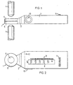
- Figs. 1 and 2 show a side view and a plane view respectively of one embodiment of an instrument according to the invention
- Fig. 3 shows a block diagram of the instrument electronics
- Fig. 4 shows a diagram of the clamping force as a function of time during one welding cycle.
- the instrument according to the invention comprises a measuring cell, generally designated 1 which, via a flexible connection 2 of rubber for example, is connected to an apparatus casing 3 containing the electronics shown in the block diagram in Fig. 3.
- the measuring cell 1 which is intended to be inserted between a pair of welding electrodes 4 in a spot welding machine, has a pair of circular plates 5 of electrically conducting material which are electrically insulated from each other by means of an intermediate insulation.
- the plates 5 are provided with flat striking surfaces 6 and carry between them a force measuring means in the form of a wire strain bridge 7 (see Fig. 3).
- the apparatus casing 3 which also serves as a handle for use of the instrument, there is an optical indicator in the form of scale 8 with a stack of light-emitting diodes 9 indicating the clamping force which the measuring cell 1 is subjected to by the welding electrodes 4. Furthermore, there is a button 10 for turning on/off and resetting, a combined scale changing control and switch 11 as well as an LED 12 which indicates if the wrong measuring range has been selected.
- the instrument In use, the instrument is held in one hand and is activated by pressing in the button 10 and holding it pressed in, whereafter the measuring cell 1 is inserted between the welding electrodes 4, as shown in Fig. 1. Then the welding machine is activated, so that a work cycle is run through. When the electrodes 4 clamp the measuring cell, any obliqueness of the instrument is compensated for by the flexible connection 2, so that the instrument is not knocked out of the hand of the user. After the welding cycle has been completed, the instrument is removed with the button 10 still pressed in, and the electrode force can be read directly on the LED stack 9. The instrument provides information both on the clamping force upon turning on of the welding current and on the maximum welding force. In Fig.
- the filled-in circles in the stack 9 represent lighted diodes, and the uppermost lighted diode in the continuous stack indicates the clamping force when the welding current is turned on, while the solitary lighted diode above the stack indicates the top value, i.e. . the maximum clamping force.
- Fig. 3 shows a block diagram of the circuits connected between the wire strain bridge 7, the plates 5 and the LED stack 9; where 20 designates an amplifier and 21 designates a voltage detector with a circuit 22 for switching on and resetting, activated by the button 10. 23 designates a switch controlled by the voltage detector, while 24 and 25 designate a peak value memory and a sampling and holding circuit respectively, which via a switch 27 controlled by a clock circuit 26 provide an analogue voltage value to a driver 28 for the LED stack 9. Before the welding current is turned on, the switch 23 is in the position shown in the figure, which means that the stack of lighted diodes grows as the clamping force of the electrodes 4 increases.
- the switch 23 changes position with the result that the driver 28 alternatingly via the switch 27 controlled by the clock circuit 26 receives voltage from the sampling and holding circuit 25 and the peak value memory 24.
- the holding circuit 25 "freezes" the level of the diode stack when the current is turned on, while the peak value memory stores the peak value of the clamping force and displays this as a single point.
- Fig. 2 shows that the clamping force between the electrodes 4, when the current was turned on, was about 3.5 kN, while the peak value was 4 kN. This sequence is illustrated in Fig. 4 and means that the squeeze time was 15 periods.
- the block diagram in Fig. 3 also includes a voltage source 28 and a scale range indicator 29, which is controlled by the selector knob 11. Finally, there is a circuit 30 for detecting the choice of a too low measuring range, which is indicated by the diode 12.
Landscapes
- Chemical & Material Sciences (AREA)
- Analytical Chemistry (AREA)
- Physics & Mathematics (AREA)
- General Physics & Mathematics (AREA)
- Engineering & Computer Science (AREA)
- Mechanical Engineering (AREA)
- General Engineering & Computer Science (AREA)
- High Energy & Nuclear Physics (AREA)
- Measurement Of Length, Angles, Or The Like Using Electric Or Magnetic Means (AREA)
- Force Measurement Appropriate To Specific Purposes (AREA)
- Resistance Welding (AREA)
Abstract
Description
- The present invention relates to a portable measuring instrument for checking the squeeze time in point welding by comparing the clamping force value when the welding current is turned on with a predetermined value, thereby indicating, when the measured clamping force value is lower than the predetermined value, that the squeeze time is too short and, when the measured value is higher than the predetermined value, that the squeeze time is too long, said instrument comprising a force measuring cell, including a wire strain bridge for example, which is insertable between a pair of welding electrodes for measuring the clamping force therebetween and which is coordinated with a pair of electrodes in a voltage detector for detecting voltage between the welding electrodes.
- The working control cycle of a mechanically driven spot welding machine is initiated by an impulse from a welding timer activating the valve which controls the working cylinder providing the electrode movement and force. When a predetermined electrode force has been reached, the welding process itself is initiated by the welding current being turned on. The time from the moment the valve controlling the electrode movement is activated up to the moment when the current is turned on is called the squeeze time, and it is of great importance that this time be correctly set. If it is too short, insuffient electrode force will be built up, resulting in poor weld quality. If it is too long, the welding cycle will be unnecessarily extended, lowering the rate of production.
- The length of the required squeeze time is dependent on a number of factors, such as the type of welding machine, air or hydraulic operation, valve and pipe arrangements, requirements on quiet and smooth operation of the equipment, etc. Thus, it is not possible to give any general values of the length of the squeeze time.
- Methods known up to now for checking that the squeeze time has a suitable length are relatively complicated and involve the moving of a recording oscilloscope with the necessary adaptor equipment to the welding machine as well as hooking up and adjustment. Such an equipment is disclosed in US-A-2 430 237 and when using it disruption of production is unavoidable.
- The purpose of the present invention is to achieve a measuring instrument which provides directly a clear picture of the squeeze process and which is small enough to be easily carried on ones person. A further purpose is to achieve an instrument which does not require special electrical connection to the welding machine thus disrupting production only very minimally.
- This is achieved according to the invention by means of an instrument in which the force measuring cell and the voltage detector are coupled via an electronic unit to optical indicating means, which only indicate the clamping force, that the voltage detector is arranged to send, when the welding current is turned on, an impulse to the electronic unit to indicate on the optical indicating means the value of the clamping force at the moment of said turning on, and that the electronic unit is arranged to retain this value regardless of changes in the clamping force after the current is turned on.
- The instrument according to the invention provides information on the magnitude of the clamping force when the welding current is turned on, which makes it possible to determine directly whether the squeeze time is too short or too long.
- The invention will be described in more detail with reference to the embodiment shown on the accompanying drawings, of which Figs. 1 and 2 show a side view and a plane view respectively of one embodiment of an instrument according to the invention, Fig. 3 shows a block diagram of the instrument electronics, and Fig. 4 shows a diagram of the clamping force as a function of time during one welding cycle.
- The instrument according to the invention comprises a measuring cell, generally designated 1 which, via a
flexible connection 2 of rubber for example, is connected to anapparatus casing 3 containing the electronics shown in the block diagram in Fig. 3. - The
measuring cell 1, which is intended to be inserted between a pair ofwelding electrodes 4 in a spot welding machine, has a pair ofcircular plates 5 of electrically conducting material which are electrically insulated from each other by means of an intermediate insulation. Theplates 5 are provided with flatstriking surfaces 6 and carry between them a force measuring means in the form of a wire strain bridge 7 (see Fig. 3). - On the
apparatus casing 3, which also serves as a handle for use of the instrument, there is an optical indicator in the form ofscale 8 with a stack of light-emittingdiodes 9 indicating the clamping force which themeasuring cell 1 is subjected to by thewelding electrodes 4. Furthermore, there is abutton 10 for turning on/off and resetting, a combined scale changing control and switch 11 as well as anLED 12 which indicates if the wrong measuring range has been selected. - In use, the instrument is held in one hand and is activated by pressing in the
button 10 and holding it pressed in, whereafter themeasuring cell 1 is inserted between thewelding electrodes 4, as shown in Fig. 1. Then the welding machine is activated, so that a work cycle is run through. When theelectrodes 4 clamp the measuring cell, any obliqueness of the instrument is compensated for by theflexible connection 2, so that the instrument is not knocked out of the hand of the user. After the welding cycle has been completed, the instrument is removed with thebutton 10 still pressed in, and the electrode force can be read directly on theLED stack 9. The instrument provides information both on the clamping force upon turning on of the welding current and on the maximum welding force. In Fig. 2, the filled-in circles in thestack 9 represent lighted diodes, and the uppermost lighted diode in the continuous stack indicates the clamping force when the welding current is turned on, while the solitary lighted diode above the stack indicates the top value, i.e. . the maximum clamping force. - Fig. 3 shows a block diagram of the circuits connected between the
wire strain bridge 7, theplates 5 and theLED stack 9; where 20 designates an amplifier and 21 designates a voltage detector with acircuit 22 for switching on and resetting, activated by thebutton 10. 23 designates a switch controlled by the voltage detector, while 24 and 25 designate a peak value memory and a sampling and holding circuit respectively, which via aswitch 27 controlled by aclock circuit 26 provide an analogue voltage value to adriver 28 for theLED stack 9. Before the welding current is turned on, theswitch 23 is in the position shown in the figure, which means that the stack of lighted diodes grows as the clamping force of theelectrodes 4 increases. When the welding current is turned on, theswitch 23 changes position with the result that thedriver 28 alternatingly via theswitch 27 controlled by theclock circuit 26 receives voltage from the sampling and holdingcircuit 25 and thepeak value memory 24. Theholding circuit 25 "freezes" the level of the diode stack when the current is turned on, while the peak value memory stores the peak value of the clamping force and displays this as a single point. - Fig. 2 shows that the clamping force between the
electrodes 4, when the current was turned on, was about 3.5 kN, while the peak value was 4 kN. This sequence is illustrated in Fig. 4 and means that the squeeze time was 15 periods. - In the welding cycle shown as an example in the diagram in Fig. 4, the turning on of the current occurred just before full electrode force was achieved and the welding current was kept on for 10 periods. Full clamping force between the electrodes was maintained for 5 periods after the current was turned off, followed by a pause of 20 periods until the start of the next welding cycle to provide time for the electrodes to be unloaded and separated from the workpiece.
- If the LED stack had given a reading of 2.5 kN, the squeeze time would have been too short, i.e. 10 periods (see Fig. 4).
- In addition to the above-mentioned electronics, the block diagram in Fig. 3 also includes a
voltage source 28 and ascale range indicator 29, which is controlled by theselector knob 11. Finally, there is acircuit 30 for detecting the choice of a too low measuring range, which is indicated by thediode 12.
Claims (4)
Applications Claiming Priority (2)
| Application Number | Priority Date | Filing Date | Title |
|---|---|---|---|
| SE8009094A SE448356B (en) | 1980-12-23 | 1980-12-23 | PORTABLE METHOD INSTRUMENT FOR CONTROL OF PLANT TIME IN POINT WELDING |
| SE8009094 | 1980-12-23 |
Publications (2)
| Publication Number | Publication Date |
|---|---|
| EP0074355A1 EP0074355A1 (en) | 1983-03-23 |
| EP0074355B1 true EP0074355B1 (en) | 1986-06-18 |
Family
ID=20342558
Family Applications (1)
| Application Number | Title | Priority Date | Filing Date |
|---|---|---|---|
| EP82900166A Expired EP0074355B1 (en) | 1980-12-23 | 1981-12-21 | Measuring instrument for checking the squeeze time in spot welding |
Country Status (6)
| Country | Link |
|---|---|
| US (1) | US4485683A (en) |
| EP (1) | EP0074355B1 (en) |
| JP (1) | JPS57502251A (en) |
| DE (1) | DE3174861D1 (en) |
| SE (1) | SE448356B (en) |
| WO (1) | WO1982002163A1 (en) |
Families Citing this family (16)
| Publication number | Priority date | Publication date | Assignee | Title |
|---|---|---|---|---|
| FR2570495B1 (en) * | 1984-09-19 | 1986-12-05 | Alsthom Atlantique | FORCE MEASUREMENT DEVICE TANGENTIALLY APPLIED TO A ROTOR PROVIDED WITH TEETH |
| DE4135537C1 (en) * | 1991-10-28 | 1993-04-08 | Harald Dipl.-Ing. 8180 Tegernsee De Preiss | |
| US5608173A (en) * | 1995-06-07 | 1997-03-04 | Sensor Developments, Inc. | Force measuring apparatus having electrically-insulated load bearing surfaces |
| US5648617A (en) * | 1995-08-25 | 1997-07-15 | Applied Robotics, Inc. | Single axis robot force sensor assembly |
| DE102004020745A1 (en) * | 2004-04-27 | 2005-11-24 | Werner & Pfleiderer Lebensmitteltechnik Gmbh | oven |
| DE202004006799U1 (en) | 2004-04-28 | 2004-07-22 | Senstronic Deutschland Gmbh | Optical measuring device |
| EP1844889B1 (en) * | 2006-04-13 | 2019-07-17 | KUKA Deutschland GmbH | Method and device for spot welding on at least one workpiece using at least one robot |
| US10056010B2 (en) | 2013-12-03 | 2018-08-21 | Illinois Tool Works Inc. | Systems and methods for a weld training system |
| US10105782B2 (en) | 2014-01-07 | 2018-10-23 | Illinois Tool Works Inc. | Feedback from a welding torch of a welding system |
| US10170019B2 (en) | 2014-01-07 | 2019-01-01 | Illinois Tool Works Inc. | Feedback from a welding torch of a welding system |
| CN106463791B (en) * | 2014-06-26 | 2021-06-04 | 罗伯特·博世有限公司 | Transmission device for transmitting electrical signals from at least one battery to at least one electronic evaluation unit |
| US10665128B2 (en) | 2014-06-27 | 2020-05-26 | Illinois Tool Works Inc. | System and method of monitoring welding information |
| US10417934B2 (en) | 2014-11-05 | 2019-09-17 | Illinois Tool Works Inc. | System and method of reviewing weld data |
| US10402959B2 (en) | 2014-11-05 | 2019-09-03 | Illinois Tool Works Inc. | System and method of active torch marker control |
| US10204406B2 (en) | 2014-11-05 | 2019-02-12 | Illinois Tool Works Inc. | System and method of controlling welding system camera exposure and marker illumination |
| US10427239B2 (en) | 2015-04-02 | 2019-10-01 | Illinois Tool Works Inc. | Systems and methods for tracking weld training arc parameters |
Family Cites Families (11)
| Publication number | Priority date | Publication date | Assignee | Title |
|---|---|---|---|---|
| DE741925C (en) * | 1941-08-01 | 1943-11-19 | Aeg | Resistance welding machine with a pressure-dependent organ that is influenced by the electrode pressure and determines the start and end of the current flow through the welding point |
| US2430237A (en) * | 1945-03-26 | 1947-11-04 | Gen Motors Corp | Weld analyzer |
| US2616014A (en) * | 1948-02-26 | 1952-10-28 | Gen Motors Corp | Weld analyzer |
| GB723366A (en) * | 1951-06-06 | 1955-02-09 | Onera (Off Nat Aerospatiale) | Apparatus for checking electric spot-welding operations |
| US2744182A (en) * | 1953-11-23 | 1956-05-01 | Rohr Aircraft Corp | Indicator for resistance welding |
| GB849494A (en) * | 1956-02-09 | 1960-09-28 | Rolls Royce | Improvements in or relating to apparatus for use in determining or observing the operating characteristics of electrical resistance welding apparatus |
| US3222923A (en) * | 1961-06-09 | 1965-12-14 | Lebow Associates Inc | Welder transducer |
| GB1162915A (en) * | 1967-07-03 | 1969-09-04 | Digital Sensors Inc | Improvements relating to electrical resistance welding |
| FR1569022A (en) * | 1968-03-27 | 1969-05-30 | ||
| US3824377A (en) * | 1972-05-10 | 1974-07-16 | Trodyne Corp | Acoustic emission spot welding controller |
| US4307608A (en) * | 1977-12-12 | 1981-12-29 | Fitness Motivation Institute Of America | Apparatus for digitally displaying muscle strength |
-
1980
- 1980-12-23 SE SE8009094A patent/SE448356B/en not_active IP Right Cessation
-
1981
- 1981-12-21 EP EP82900166A patent/EP0074355B1/en not_active Expired
- 1981-12-21 WO PCT/SE1981/000386 patent/WO1982002163A1/en not_active Ceased
- 1981-12-21 DE DE8282900166T patent/DE3174861D1/en not_active Expired
- 1981-12-21 US US06/414,260 patent/US4485683A/en not_active Expired - Fee Related
- 1981-12-21 JP JP50018882A patent/JPS57502251A/ja active Pending
Also Published As
| Publication number | Publication date |
|---|---|
| EP0074355A1 (en) | 1983-03-23 |
| WO1982002163A1 (en) | 1982-07-08 |
| SE448356B (en) | 1987-02-16 |
| US4485683A (en) | 1984-12-04 |
| DE3174861D1 (en) | 1986-07-24 |
| JPS57502251A (en) | 1982-12-23 |
| SE8009094L (en) | 1982-06-24 |
Similar Documents
| Publication | Publication Date | Title |
|---|---|---|
| US4485683A (en) | Instrument for measuring the clamping force between a pair of welding electrodes | |
| US8037598B2 (en) | Method of repetitively accomplishing mechanical action of a tool member | |
| CN109193353B (en) | Arc generating equipment and method for evaluating the resistance to arc ablation of electrical contact materials | |
| JPS6488147A (en) | Electrolyte measuring apparatus | |
| GB1591817A (en) | Fluoride coating apparatus | |
| JPH074506Y2 (en) | Meter equipped with measuring probe | |
| EP0483150B1 (en) | Acupuncture locating device | |
| SE449709C (en) | APPLIANCE FOR DIRECT SIZING OF THE WORK PIECE IN A NUMERICALLY CONTROLLED TOOL MACHINE | |
| CN106226608A (en) | A kind of cable phase sequence determinator | |
| US5437181A (en) | Concrete slump testing | |
| US2732518A (en) | Bore hole detecting circuit and bore hole firing | |
| JPH10170571A (en) | Conduction state of wiring equipment, and insulation resistance measuring device | |
| CN213122149U (en) | Electronic components's detection platform | |
| JPS56108971A (en) | Resistance measuring method and device using said measuring method | |
| EP0551199A2 (en) | Electrical insulation and continuity tester | |
| EP0389784A3 (en) | Electrical shaving apparatus | |
| CN219715686U (en) | Vibration rod open-circuit and short-circuit tester with high testing efficiency | |
| CN215116672U (en) | Remote discharge detection device for battery pack | |
| CN218122215U (en) | PTC break-make testboard that shocks resistance | |
| JP2737144B2 (en) | Battery with remaining capacity display function | |
| CN223139753U (en) | An insulation detection device for electric tools | |
| KR0159867B1 (en) | Local vacuum measuring device for battery vacuum drying oven | |
| CN211155735U (en) | Fat detector | |
| JPH067945A (en) | Thermocouple wire welding unit | |
| JPH0626860Y2 (en) | Battery voltage inspection device |
Legal Events
| Date | Code | Title | Description |
|---|---|---|---|
| PUAI | Public reference made under article 153(3) epc to a published international application that has entered the european phase |
Free format text: ORIGINAL CODE: 0009012 |
|
| 17P | Request for examination filed |
Effective date: 19821227 |
|
| AK | Designated contracting states |
Designated state(s): BE DE FR GB NL |
|
| GRAA | (expected) grant |
Free format text: ORIGINAL CODE: 0009210 |
|
| AK | Designated contracting states |
Kind code of ref document: B1 Designated state(s): BE DE FR GB NL |
|
| REF | Corresponds to: |
Ref document number: 3174861 Country of ref document: DE Date of ref document: 19860724 |
|
| ET | Fr: translation filed | ||
| BECA | Be: change of holder's address |
Free format text: 860618 *ABACUS A.B.BOKVAGEN 2, S-293 00 OLOFSTROM |
|
| BECH | Be: change of holder |
Free format text: 860618 *ABACUS A.B. |
|
| PGFP | Annual fee paid to national office [announced via postgrant information from national office to epo] |
Ref country code: NL Payment date: 19861231 Year of fee payment: 6 |
|
| PLBE | No opposition filed within time limit |
Free format text: ORIGINAL CODE: 0009261 |
|
| STAA | Information on the status of an ep patent application or granted ep patent |
Free format text: STATUS: NO OPPOSITION FILED WITHIN TIME LIMIT |
|
| 26N | No opposition filed | ||
| PG25 | Lapsed in a contracting state [announced via postgrant information from national office to epo] |
Ref country code: BE Effective date: 19871231 |
|
| REG | Reference to a national code |
Ref country code: GB Ref legal event code: 732 |
|
| REG | Reference to a national code |
Ref country code: FR Ref legal event code: TP |
|
| BERE | Be: lapsed |
Owner name: ABACUS A.B. Effective date: 19871231 |
|
| PG25 | Lapsed in a contracting state [announced via postgrant information from national office to epo] |
Ref country code: NL Effective date: 19880701 |
|
| NLS | Nl: assignments of ep-patents |
Owner name: ABACUS AB TE OLOFSTROEM, ZWEDEN. |
|
| NLV4 | Nl: lapsed or anulled due to non-payment of the annual fee | ||
| PGFP | Annual fee paid to national office [announced via postgrant information from national office to epo] |
Ref country code: GB Payment date: 19901220 Year of fee payment: 10 |
|
| PGFP | Annual fee paid to national office [announced via postgrant information from national office to epo] |
Ref country code: FR Payment date: 19901228 Year of fee payment: 10 |
|
| PGFP | Annual fee paid to national office [announced via postgrant information from national office to epo] |
Ref country code: DE Payment date: 19910208 Year of fee payment: 10 |
|
| PG25 | Lapsed in a contracting state [announced via postgrant information from national office to epo] |
Ref country code: GB Effective date: 19911221 |
|
| GBPC | Gb: european patent ceased through non-payment of renewal fee | ||
| PG25 | Lapsed in a contracting state [announced via postgrant information from national office to epo] |
Ref country code: FR Effective date: 19920831 |
|
| PG25 | Lapsed in a contracting state [announced via postgrant information from national office to epo] |
Ref country code: DE Effective date: 19920901 |
|
| REG | Reference to a national code |
Ref country code: FR Ref legal event code: ST |