EP0074180B1 - Ventilaufbau - Google Patents
Ventilaufbau Download PDFInfo
- Publication number
- EP0074180B1 EP0074180B1 EP82304128A EP82304128A EP0074180B1 EP 0074180 B1 EP0074180 B1 EP 0074180B1 EP 82304128 A EP82304128 A EP 82304128A EP 82304128 A EP82304128 A EP 82304128A EP 0074180 B1 EP0074180 B1 EP 0074180B1
- Authority
- EP
- European Patent Office
- Prior art keywords
- cup
- housing
- projections
- head
- assembly
- Prior art date
- Legal status (The legal status is an assumption and is not a legal conclusion. Google has not performed a legal analysis and makes no representation as to the accuracy of the status listed.)
- Expired
Links
Images
Classifications
-
- B—PERFORMING OPERATIONS; TRANSPORTING
- B65—CONVEYING; PACKING; STORING; HANDLING THIN OR FILAMENTARY MATERIAL
- B65D—CONTAINERS FOR STORAGE OR TRANSPORT OF ARTICLES OR MATERIALS, e.g. BAGS, BARRELS, BOTTLES, BOXES, CANS, CARTONS, CRATES, DRUMS, JARS, TANKS, HOPPERS, FORWARDING CONTAINERS; ACCESSORIES, CLOSURES, OR FITTINGS THEREFOR; PACKAGING ELEMENTS; PACKAGES
- B65D83/00—Containers or packages with special means for dispensing contents
- B65D83/14—Containers or packages with special means for dispensing contents for delivery of liquid or semi-liquid contents by internal gaseous pressure, i.e. aerosol containers comprising propellant for a product delivered by a propellant
- B65D83/44—Valves specially adapted therefor; Regulating devices
- B65D83/48—Lift valves, e.g. operated by push action
-
- B—PERFORMING OPERATIONS; TRANSPORTING
- B65—CONVEYING; PACKING; STORING; HANDLING THIN OR FILAMENTARY MATERIAL
- B65D—CONTAINERS FOR STORAGE OR TRANSPORT OF ARTICLES OR MATERIALS, e.g. BAGS, BARRELS, BOTTLES, BOXES, CANS, CARTONS, CRATES, DRUMS, JARS, TANKS, HOPPERS, FORWARDING CONTAINERS; ACCESSORIES, CLOSURES, OR FITTINGS THEREFOR; PACKAGING ELEMENTS; PACKAGES
- B65D83/00—Containers or packages with special means for dispensing contents
- B65D83/14—Containers or packages with special means for dispensing contents for delivery of liquid or semi-liquid contents by internal gaseous pressure, i.e. aerosol containers comprising propellant for a product delivered by a propellant
- B65D83/16—Containers or packages with special means for dispensing contents for delivery of liquid or semi-liquid contents by internal gaseous pressure, i.e. aerosol containers comprising propellant for a product delivered by a propellant characterised by the actuating means
- B65D83/20—Containers or packages with special means for dispensing contents for delivery of liquid or semi-liquid contents by internal gaseous pressure, i.e. aerosol containers comprising propellant for a product delivered by a propellant characterised by the actuating means operated by manual action, e.g. button-type actuator or actuator caps
Definitions
- This invention concerns a valve assembly for a container for pressurised fluid, and a pressurised fluid container including such an assembly.
- the invention relates to a valve assembly for an aerosol container, for example, around which the container can be charged with a pressurising medium or propellant and through which subsequently pressurised fluid can be dispensed.
- One known type of aerosol valve assembly comprises a cup mounting the assembly to the aerosol body, a valve housing fitted in the cup, and valve means supported by the cup and the valve housing.
- the housing has a head which is retained within the cup by crimps in the side wall of the cup engaging behind the head, and the valve means include a valve stem extending from within the housing out through the end wall of the cup and an elastomeric gasket encircling the valve stem and arranged between the head of the housing and the end wall of the cup.
- the valve stem is resiliently biassed into an extended position and normally holds the gasket so that it seals passages from the exterior of the cup through to the interior of the container. When the valve stem is depressed, however, the gasket is deformed to open one or more of these passages so that the container can be charged with propellant and subsequently pressurised fluid can be discharged.
- the gasket is arranged to be deformed to provide a first passage from an operating button mounted on the stem into a space between the head of the valve housing and the side wall of the cup and a second passage partly in parallel to the first, which extends from the button through the interior of the housing to a dip-tube in the container.
- a third charging passage is available along the flow path which is used for dispensing, but in the reverse direction, that is to say, through the operating button, and the valve stem to the interior of the housing, and thence to the dip-tube.
- the major part of the propellant flow will occur through the first passage.
- the head of the valve housing is continuous, that is to say, un- grooved or unbeaded, and a small clearance is provided between the head and side wall of the cup for the passage of propellant during charging.
- the housing is located relative to the cup by the engagement of the crimps in the cup wall behind the head and with the body of the housing.
- valve assembly is a development of that just mentioned and has a substantial passage formed between the head of the valve housing and the side wall of the cup for ease of filling.
- the housing is again secured relative to the cup by crimps as previously mentioned and six equi-spaced locating ribs formed around the housing head serve to centre the head within the cup by contacting the interior of the cup.
- the housing has a thickened tubular portion beneath the head so as to provide a reinforcing collar or body ring which increases the rigidity of the housing enabling it better to withstand, without gross deformation, the radially inward pressures generated at the crimps, these pressures serving to restrain relative movement, primarily tilting movement, of the housing relative to the cup.
- the head of the housing and the side wall of the cup have been formed with only a narrow clearance between the two and the area of the flow-path which they define is increased by providing seven equi-spaced wide grooves in the head, the width of the grooves being approximately the same as that of the residual head regions between them. Again, location is achieved by the engagement of crimps behind the head and against a continuous reinforcing collar on the housing body. Eight crimps were provided of similar width to that of the grooves, but it was found that occassionally valve body misalignment would occur.
- the head of the valve housing has six radial projections 45, and between these projections there are spaces 25 through which propellant fluid can flow during filling.
- a tubular portion which includes ribs or thickened portions 59 between which there are passages, also for the flow of propellant fluid during filling. These passages are apparently exactly in line with the spaces 25 in the head.
- the valve housing is retained in a lid or cup 42 by means of six deformations 44 which extend inwardly below the six projections 45.
- valve body 41 has to be correctly oriented relative to the lid or cup 42 before the retaining deformations 44 are formed.
- alternate circumferentially spaced apart areas of the tubular portion namely the ribs 59
- the intervening circumferentially spaced apart areas of the tubular portion namely the passages between the thickened portions 59, are clearly structures completely different from the ribs 59 themselves and serve to permit additional propellant fluid flow, without taking any part in the retention of the housing within the lid or cup 42.
- This segmentation of the housing on a scale comparable with the scale of the deformations 44 requires the additional step of relative orientation during assembly.
- the present invention has limited similarity with that of the above proposal in that internal projections on the cup also contact spaced apart areas of a tubular portion, and the tubular portion is formed with flow paths to enhance propellant flow.
- the present invention is totally different from what is taught, described and claimed in British Published Application No. 2,049,827A.
- the valve housing is not angularly orientated relative to the cup during assembly, the housing flow paths have no special angular relationship with the contact areas of the projections on the cup and, regarded on the scale of the projections, the tubular portion comes sufficiently close to being continuous (i.e. non-segmented) that it can be treated as continuous for assembly purposes.
- the invention also improves on those prior art constructions which did not require orientation, in that the firmness of location previously achieved by having the projections firmly engage with a tubular portion adjacent to the head is retained while the total flow area for incoming propellant, at the level of the projections, is increased by the provision of extra flow paths.
- the exterior wall of the head is formed with grooves which extend into said tubular portion so as to provide said flow paths.
- a substantial flow area may be provided also between the housing head and the side wall of the cup.
- the number of grooves provided is significantly greater than six and, in the embodiment described below, there are sixteen grooves.
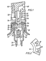
- valve assembly illustrated in the drawings comprises a sheet metal valve mounting cup 10 secured to an aerosol container body (not shown) in a conventional manner.
- the cup 10 carries valve means 14 including a valve housing 12.
- the cup 10 is formed with a plurality of spaced projections in the form of crimps 16 which engage beneath a head 18 of the housing 12. Further engagement between the crimps and the housing occurs at a tubular portion in the form of reinforcing collar or body ring 20 at which the housing 12 is thickened beneath the head 18. These engagements are such that the housing is accurately located within the mounting cup against any substantial movement in either the axial or the radial directions, and any substantial tilting movement, as will later become more fully apparent.
- a passage 22 is defined between the exterior of the housing 12 and the side wall of the cup 10 by a small clearance 24 between the periphery of the head 18 and the side wall, and grooves 26 extending continuously down both the head 18 and the body ring 20.
- the grooves 26 are both many and narrow and they are significantly narrower than the width of the crimps 16, so that the crimps 16 cannot penetrate into them to any substantial extent.
- the number and depth of the grooves 26 is sufficient to provide a substantial flow area for the passage 22. In this instance, there are 16 of the grooves 26 and they extend radially to a substantial extent into the head 18 and body ring 20.
- the remanent thickness of material at the base of the grooves is nevertheless substantial and the housing remains correspondingly robust and not prone to distortion.
- the housing 12 is hollow and its interior communicates with a dip-tube 28 by way of a nozzle 30.
- the valve means 14 are arranged to control opening of the passage 22 and the interior of the housing 12 to the exterior of the cup 10 for pressurisation and product dispensing.
- the valve means 14 are provided with a valve stem 32 movable within the housing 12, and an elastomeric gasket 34 encircling the valve stem 32 and clamped between the housing 12 and the end wall of the cup 10 by the engagement of the crimps 16 with the housing.
- the valve stem 32 projects through the cup end wall and, with this end wall, defines an annular propellant inlet opening 36 into the cup.
- the valve stem contains a bore 38 which communicates with an aperture 40 extending through the wall of the stem to an annular seat 42 for receiving the inner periphery of the gasket 34.
- the stem 32 is resiliently biassed outwardly of the cup 10 (i.e. upwardly as shown) by a spring 60 and thus normally occupies the position illustrated in Fig. 1 in which the gasket is flat and closes both the annular opening 36 and the aperture 40.
- This passage is the passage used for product dispensing; it also serves in the reverse direction during pressurisation of the container, when it is one of three passages available for propellant flow into the container.
- Depression of the valve stem 32 is effected by operation of the button 46 mounted on the outer end of the stem 32.
- the button 46 is provided with a discharge aperture 48 in communication with the bore 38 and with a pressurising aperture 50 which opens into an annular region 52 of the button 46 in communication with an annular opening 54 in the base of the button.
- the opening 54 is arranged to overlie the opening 36 between the cup 10 and valve stem 32 when the stem is depressed to bring the button 46 into engagement with the cup 10.
- the button 46 is released, so allowing the stem 32 to return resiliently to its normal position in which the gasket 34 seals the container. Thereafter the container may be used in conventional manner to dispense products by depressing the button so as to open the aperture 40 and allow product to be discharged through the aperture 48 via the dip-tube 28, the interior of the housing, and the stem bore 38.
- Rapid pressurisation of the container is possible as a result of combined flow through the inside of the housing and between the housing and the cup; the speed of pressurisation is enhanced by the substantial flow area presented by the passage 22.
- the grooves 26 provide a substantial flow-path between the housing 12 and the cup 10 in the form of a multiplicity of small individual flow paths at positions 62 in Fig. 2.
- these flow paths do not impair the location of the housing in the assembly since they are not sufficiently wide to accommodate any substantial part of the crimps 16.
- they can never be restricted by the crimps to any substantial extent, irrespective of the relative orientation of the housing and the cup, so the extra flow area they provide will always be available.
- sixteen grooves are provided. However, this particular number is not essential, and other numbers of grooves may be used; preferably, significantly more than six grooves are provided. Preferably the grooves are equi-spaced and extend continuously along the whole length of the head 18 and body ring 20 as shown.
Landscapes
- Chemical & Material Sciences (AREA)
- Dispersion Chemistry (AREA)
- Engineering & Computer Science (AREA)
- Mechanical Engineering (AREA)
- Containers And Packaging Bodies Having A Special Means To Remove Contents (AREA)
- Nozzles (AREA)
- Filling Or Discharging Of Gas Storage Vessels (AREA)
Claims (7)
Priority Applications (1)
| Application Number | Priority Date | Filing Date | Title |
|---|---|---|---|
| AT82304128T ATE12085T1 (de) | 1981-08-06 | 1982-08-04 | Ventilaufbau. |
Applications Claiming Priority (2)
| Application Number | Priority Date | Filing Date | Title |
|---|---|---|---|
| GB8124007 | 1981-08-06 | ||
| GB8124007 | 1981-08-06 |
Publications (2)
| Publication Number | Publication Date |
|---|---|
| EP0074180A1 EP0074180A1 (de) | 1983-03-16 |
| EP0074180B1 true EP0074180B1 (de) | 1985-03-13 |
Family
ID=10523732
Family Applications (1)
| Application Number | Title | Priority Date | Filing Date |
|---|---|---|---|
| EP82304128A Expired EP0074180B1 (de) | 1981-08-06 | 1982-08-04 | Ventilaufbau |
Country Status (19)
| Country | Link |
|---|---|
| US (1) | US4503999A (de) |
| EP (1) | EP0074180B1 (de) |
| JP (1) | JPS5933428B2 (de) |
| AR (1) | AR228193A1 (de) |
| AT (1) | ATE12085T1 (de) |
| AU (1) | AU536818B2 (de) |
| BR (1) | BR8204619A (de) |
| CA (1) | CA1188270A (de) |
| DE (1) | DE3262553D1 (de) |
| DK (1) | DK347782A (de) |
| ES (1) | ES514773A0 (de) |
| FI (1) | FI822756L (de) |
| GB (1) | GB2104597B (de) |
| GR (1) | GR77993B (de) |
| HU (1) | HU184997B (de) |
| IN (1) | IN156953B (de) |
| NO (1) | NO822679L (de) |
| PT (1) | PT75383B (de) |
| ZA (1) | ZA825529B (de) |
Families Citing this family (7)
| Publication number | Priority date | Publication date | Assignee | Title |
|---|---|---|---|---|
| GB8319353D0 (en) * | 1983-07-18 | 1983-08-17 | Aerosol Inventions Dev | Valve assembly |
| DE4438364A1 (de) * | 1994-10-27 | 1996-05-02 | Pfeiffer Erich Gmbh & Co Kg | Austragvorrichtung für Medien sowie Verfahren und Vorrichtung zur Befüllung einer Austragvorrichtung |
| US5881929A (en) * | 1997-04-25 | 1999-03-16 | Summit Packaging Systems, Inc. | Plastic coated mounting cup for spray button seal |
| US6152190A (en) * | 1999-04-15 | 2000-11-28 | Summit Packaging Systems, Inc. | Actuator with resilient annular skirt for improved seal during button-on-filling process |
| US6161599A (en) | 1999-04-15 | 2000-12-19 | Summit Packaging Systems, Inc, | Actuator with a longitudinal filling passageway communicating with each formed internal compartment |
| GB2414016B (en) * | 2004-03-26 | 2007-04-11 | Diageo Ireland | A valve assembly for a beverage dispenser |
| FR2885889B1 (fr) * | 2005-05-20 | 2007-10-19 | Valois Sas | Valve de distribution de produit fluide |
Citations (1)
| Publication number | Priority date | Publication date | Assignee | Title |
|---|---|---|---|---|
| DE2503626A1 (de) * | 1975-01-29 | 1976-08-05 | Praezisions Ventil Gmbh | Ventil fuer druckgaspackungen |
Family Cites Families (7)
| Publication number | Priority date | Publication date | Assignee | Title |
|---|---|---|---|---|
| DE1400707A1 (de) * | 1963-05-29 | 1968-10-17 | Abplanalp Robert H | Fuelleinrichtung fuer Aerosolbehaelter mit einer ein Abgabeventil tragenden Verschlusskappe |
| DE1250362B (de) * | 1964-03-20 | |||
| US3416770A (en) * | 1967-01-11 | 1968-12-17 | Scovill Manufacturing Co | Aerosol valve unit |
| US3658214A (en) * | 1970-05-01 | 1972-04-25 | Walter C Beard | Metering valve for fluid dispenser |
| DE2206079B2 (de) * | 1972-02-09 | 1973-12-06 | Deutsche Praezisions-Ventil Gmbh, 6234 Hattersheim | Ventil für Druckgaspackungen |
| GB1534873A (en) * | 1975-12-11 | 1978-12-06 | Metal Box Co Ltd | Valve assemblies for pressurised dispensing containers |
| DE2912081A1 (de) * | 1979-03-27 | 1980-10-02 | Perfect Ventil Gmbh | Ventil fuer druckgaspackungen |
-
1982
- 1982-07-30 ZA ZA825529A patent/ZA825529B/xx unknown
- 1982-08-02 AU AU86677/82A patent/AU536818B2/en not_active Ceased
- 1982-08-03 CA CA000408640A patent/CA1188270A/en not_active Expired
- 1982-08-03 DK DK347782A patent/DK347782A/da not_active Application Discontinuation
- 1982-08-03 US US06/404,775 patent/US4503999A/en not_active Expired - Fee Related
- 1982-08-04 DE DE8282304128T patent/DE3262553D1/de not_active Expired
- 1982-08-04 AT AT82304128T patent/ATE12085T1/de not_active IP Right Cessation
- 1982-08-04 GB GB08222439A patent/GB2104597B/en not_active Expired
- 1982-08-04 GR GR68957A patent/GR77993B/el unknown
- 1982-08-04 EP EP82304128A patent/EP0074180B1/de not_active Expired
- 1982-08-05 PT PT75383A patent/PT75383B/pt unknown
- 1982-08-05 BR BR8204619A patent/BR8204619A/pt unknown
- 1982-08-05 JP JP57135781A patent/JPS5933428B2/ja not_active Expired
- 1982-08-05 ES ES514773A patent/ES514773A0/es active Granted
- 1982-08-05 NO NO822679A patent/NO822679L/no unknown
- 1982-08-05 HU HU822520A patent/HU184997B/hu not_active IP Right Cessation
- 1982-08-06 IN IN930/CAL/82A patent/IN156953B/en unknown
- 1982-08-06 AR AR290241A patent/AR228193A1/es active
- 1982-08-06 FI FI822756A patent/FI822756L/fi not_active Application Discontinuation
Patent Citations (1)
| Publication number | Priority date | Publication date | Assignee | Title |
|---|---|---|---|---|
| DE2503626A1 (de) * | 1975-01-29 | 1976-08-05 | Praezisions Ventil Gmbh | Ventil fuer druckgaspackungen |
Also Published As
| Publication number | Publication date |
|---|---|
| DK347782A (da) | 1983-02-07 |
| FI822756L (fi) | 1983-02-07 |
| ES8308017A1 (es) | 1983-08-16 |
| FI822756A0 (fi) | 1982-08-06 |
| AU8667782A (en) | 1983-08-18 |
| GR77993B (de) | 1984-09-26 |
| BR8204619A (pt) | 1983-07-26 |
| JPS5933428B2 (ja) | 1984-08-15 |
| HU184997B (en) | 1984-11-28 |
| US4503999A (en) | 1985-03-12 |
| GB2104597A (en) | 1983-03-09 |
| CA1188270A (en) | 1985-06-04 |
| NO822679L (no) | 1983-02-07 |
| AR228193A1 (es) | 1983-01-31 |
| GB2104597B (en) | 1984-09-12 |
| ATE12085T1 (de) | 1985-03-15 |
| ES514773A0 (es) | 1983-08-16 |
| PT75383B (en) | 1984-10-31 |
| PT75383A (en) | 1982-09-01 |
| EP0074180A1 (de) | 1983-03-16 |
| ZA825529B (en) | 1983-11-30 |
| DE3262553D1 (en) | 1985-04-18 |
| JPS5849460A (ja) | 1983-03-23 |
| IN156953B (de) | 1985-12-21 |
| AU536818B2 (en) | 1984-05-24 |
Similar Documents
| Publication | Publication Date | Title |
|---|---|---|
| US4015757A (en) | Rapid charging valve for a pressurized dispenser | |
| EP0191614B1 (de) | Ventil für unter Druck stehende Abgabebehälter | |
| US6394321B1 (en) | Aerosol powder valve | |
| US5292033A (en) | Dispenser for a liquid to pasty product and subplate for a dispenser of this kind | |
| EP1117600B1 (de) | Pulveraerosolventil | |
| US4078705A (en) | Valves for pressurized dispensers | |
| US4824075A (en) | Tilt action dispensing valve assembly | |
| US3333744A (en) | Valve and nozzle construction for aerosol whipped cream dispenser | |
| US3158298A (en) | Aerosol valve-fast pressure fill type | |
| US3319669A (en) | Aerosol dispenser | |
| US6619515B1 (en) | Aerosol tilt valve | |
| US3838799A (en) | Rapid charging valve housing | |
| EP0074180B1 (de) | Ventilaufbau | |
| US3845887A (en) | Pressurized aerosol dispenser valve and gasket | |
| US4410110A (en) | Valve-and-lid assembly for a container | |
| US3272403A (en) | Valve for pressure container | |
| US3918611A (en) | Pressure relief system for an aerosol dispenser | |
| US3219069A (en) | Aerosol valve | |
| US3407975A (en) | Aerosol container and cap therefor | |
| US3675824A (en) | Aerosol can with propellant actuated slide piston | |
| US3158297A (en) | Aerosol valve which also functions as a pressure filling means | |
| US4615470A (en) | Valve assembly for container of pressurized fluid | |
| US3550813A (en) | Hand-held dispenser for mixing fluids | |
| US3791561A (en) | Pressure relief system for an aerosol dispenser | |
| US4730752A (en) | Anti-seating valve cup |
Legal Events
| Date | Code | Title | Description |
|---|---|---|---|
| PUAI | Public reference made under article 153(3) epc to a published international application that has entered the european phase |
Free format text: ORIGINAL CODE: 0009012 |
|
| AK | Designated contracting states |
Designated state(s): AT BE CH DE FR GB IT LI LU NL SE |
|
| 17P | Request for examination filed |
Effective date: 19830423 |
|
| ITF | It: translation for a ep patent filed |
Owner name: DR. ING. A. RACHELI & C. |
|
| GRAA | (expected) grant |
Free format text: ORIGINAL CODE: 0009210 |
|
| AK | Designated contracting states |
Designated state(s): AT BE CH DE FR GB IT LI LU NL SE |
|
| REF | Corresponds to: |
Ref document number: 12085 Country of ref document: AT Date of ref document: 19850315 Kind code of ref document: T |
|
| REF | Corresponds to: |
Ref document number: 3262553 Country of ref document: DE Date of ref document: 19850418 |
|
| ET | Fr: translation filed | ||
| PGFP | Annual fee paid to national office [announced via postgrant information from national office to epo] |
Ref country code: AT Payment date: 19850708 Year of fee payment: 4 |
|
| PG25 | Lapsed in a contracting state [announced via postgrant information from national office to epo] |
Ref country code: LU Free format text: LAPSE BECAUSE OF NON-PAYMENT OF DUE FEES Effective date: 19850831 |
|
| PGFP | Annual fee paid to national office [announced via postgrant information from national office to epo] |
Ref country code: NL Payment date: 19850831 Year of fee payment: 4 |
|
| PLBI | Opposition filed |
Free format text: ORIGINAL CODE: 0009260 |
|
| 26 | Opposition filed |
Opponent name: DEUTSCHE PRAEZISIONSVENTIL GMBH Effective date: 19851211 |
|
| NLR1 | Nl: opposition has been filed with the epo |
Opponent name: DEUTSCHE PRAEZISIONSVENTIL GMBH |
|
| PG25 | Lapsed in a contracting state [announced via postgrant information from national office to epo] |
Ref country code: GB Effective date: 19860804 |
|
| PG25 | Lapsed in a contracting state [announced via postgrant information from national office to epo] |
Ref country code: SE Effective date: 19860805 |
|
| RDAG | Patent revoked |
Free format text: ORIGINAL CODE: 0009271 |
|
| STAA | Information on the status of an ep patent application or granted ep patent |
Free format text: STATUS: PATENT REVOKED |
|
| BERE | Be: lapsed |
Owner name: METAL BOX P.L.C. Effective date: 19860831 |
|
| 27W | Patent revoked |
Effective date: 19861017 |
|
| REG | Reference to a national code |
Ref country code: CH Ref legal event code: PL |
|
| NLR2 | Nl: decision of opposition | ||
| GBPC | Gb: european patent ceased through non-payment of renewal fee | ||
| REG | Reference to a national code |
Ref country code: FR Ref legal event code: ST |
|
| EUG | Se: european patent has lapsed |
Ref document number: 82304128.0 Effective date: 19870812 |