EP0074173B1 - Improvements in or relating to magnetrons - Google Patents
Improvements in or relating to magnetrons Download PDFInfo
- Publication number
- EP0074173B1 EP0074173B1 EP82303999A EP82303999A EP0074173B1 EP 0074173 B1 EP0074173 B1 EP 0074173B1 EP 82303999 A EP82303999 A EP 82303999A EP 82303999 A EP82303999 A EP 82303999A EP 0074173 B1 EP0074173 B1 EP 0074173B1
- Authority
- EP
- European Patent Office
- Prior art keywords
- magnetron
- tines
- cavity
- tuning fork
- tuning
- Prior art date
- Legal status (The legal status is an assumption and is not a legal conclusion. Google has not performed a legal analysis and makes no representation as to the accuracy of the status listed.)
- Expired
Links
- 230000010355 oscillation Effects 0.000 claims description 7
- 230000008878 coupling Effects 0.000 claims description 4
- 238000010168 coupling process Methods 0.000 claims description 4
- 238000005859 coupling reaction Methods 0.000 claims description 4
- 239000004020 conductor Substances 0.000 claims description 3
- OCDRLZFZBHZTKQ-NMUBGGKPSA-N onetine Chemical compound C[C@@H](O)[C@@]1(O)C[C@@H](C)[C@@](C)(O)C(=O)OC\C2=C\CN(C)CC[C@@H](OC1=O)C2=O OCDRLZFZBHZTKQ-NMUBGGKPSA-N 0.000 claims 1
- 125000004122 cyclic group Chemical group 0.000 abstract description 3
- 230000000694 effects Effects 0.000 abstract description 2
- 230000003993 interaction Effects 0.000 description 5
- XEEYBQQBJWHFJM-UHFFFAOYSA-N Iron Chemical compound [Fe] XEEYBQQBJWHFJM-UHFFFAOYSA-N 0.000 description 4
- 230000004048 modification Effects 0.000 description 3
- 238000012986 modification Methods 0.000 description 3
- RYGMFSIKBFXOCR-UHFFFAOYSA-N Copper Chemical compound [Cu] RYGMFSIKBFXOCR-UHFFFAOYSA-N 0.000 description 2
- 229910052802 copper Inorganic materials 0.000 description 2
- 239000010949 copper Substances 0.000 description 2
- 229910052742 iron Inorganic materials 0.000 description 2
- 239000000463 material Substances 0.000 description 2
- 230000002411 adverse Effects 0.000 description 1
- 230000004075 alteration Effects 0.000 description 1
- 230000001419 dependent effect Effects 0.000 description 1
- 238000006073 displacement reaction Methods 0.000 description 1
- 230000005684 electric field Effects 0.000 description 1
- 230000005226 mechanical processes and functions Effects 0.000 description 1
- 239000002184 metal Substances 0.000 description 1
- 229910052751 metal Inorganic materials 0.000 description 1
- 230000035939 shock Effects 0.000 description 1
Images


Classifications
-
- H—ELECTRICITY
- H01—ELECTRIC ELEMENTS
- H01J—ELECTRIC DISCHARGE TUBES OR DISCHARGE LAMPS
- H01J25/00—Transit-time tubes, e.g. klystrons, travelling-wave tubes, magnetrons
- H01J25/50—Magnetrons, i.e. tubes with a magnet system producing an H-field crossing the E-field
- H01J25/52—Magnetrons, i.e. tubes with a magnet system producing an H-field crossing the E-field with an electron space having a shape that does not prevent any electron from moving completely around the cathode or guide electrode
- H01J25/54—Magnetrons, i.e. tubes with a magnet system producing an H-field crossing the E-field with an electron space having a shape that does not prevent any electron from moving completely around the cathode or guide electrode having only one cavity or other resonator, e.g. neutrode tubes
- H01J25/55—Coaxial cavity magnetrons
-
- H—ELECTRICITY
- H01—ELECTRIC ELEMENTS
- H01J—ELECTRIC DISCHARGE TUBES OR DISCHARGE LAMPS
- H01J23/00—Details of transit-time tubes of the types covered by group H01J25/00
- H01J23/16—Circuit elements, having distributed capacitance and inductance, structurally associated with the tube and interacting with the discharge
- H01J23/18—Resonators
- H01J23/20—Cavity resonators; Adjustment or tuning thereof
- H01J23/207—Tuning of single resonator
Definitions
- This invention relates to magnetrons.
- a magnetron produces a microwave output signal whose frequency is primarily dependent on the frequency characteristics of a resonant chamber associated with the magnetron. By altering the electrical properties of the chamber, the frequency of oscillation of the magnetron can be adjusted and this is often necessary to provide fine tuning of its output frequency. It is sometimes desirable to sweep the frequency of resonance periodically over a predetermined frequency range, but it is difficult to obtain fast sweep rates since the mechanical actuators and linkages usually necessary to produce an alteration of the electrical properties of the resonator exhibit a relatively great mechanical inertia.
- a co-axial magnetron includes an evacuated housing which contains within it an annular resonant cavity which surrounds a cathode and which determines the frequency of oscillation of a microwave signal generated by the magnetron; tuning fork means mounted within the evacuated housing and operative to induce vibratory motion in the outer cylindrical walls of said annular resonant cavity so as to cyclically alter its resonant frequency, the inner cylindrical surfaces of the tines of the tuning fork means having a substantially circular base and following the shape of the annular resonant cavity; and means responsive to the movement of the outer cylindrical walls for generating a signal representative of the instantaneous frequency of the cavity.
- the tuning fork means can itself constitute the whole or part of the outer cylindrical walls of the annular resonant cavity, or instead the tines of the tuning fork means can be coupled to thin flexible material of general cylindrical form which constitutes the outer walls of the cavity.
- the mean cross-sectional shape of the cavity may not be exactly circular and the departure of the shape from a true circle which occurs as the walls are vibrated can be minimised by the use of more than one tuning fork means arranged around the outer walls of the cavity.
- the movement of the walls or the movement of the tines of the tuning fork can be monitored, whichever is the more convenient.
- a co-axial magnetron consists of an annular cavity 1 which surrounds an elongate cathode 2 and an interaction space 3 consisting of a large number of individual cavities which are spaced apart by anode vanes positioned around the cathode 2. These cavities constitute the anode structure, and a magnetic field is produced within the interaction space 3 by means of magnets 4 and 5.
- the annular cavity 1 is formed by a pair of general cylindrical walls, the inner surface 30 of which is constituted by the anode structure and the outer surface 31 of which is constituted by one face of a tuning fork 6, which is firmly mounted at its base 7 to a rigid outer housing 8 which constitutes an evacuated envelope.
- the base 9 of the housing 8 constitutes one end plate of the cavity 1, and the opposite end plate of the cavity is constituted by a movable annular ring 10.
- the base 9, the ring 10 and the tuning fork 6 are made of a robust material which is suited to the mechanical functions which they have to provide, whilst the faces of these bodies which constitute the cavity 1 itself are copper plated to ensure good electrical conductivity.
- electrons are emitted by the cathode 2 into the interaction space 3 when a high voltage, usually in pulse form, is applied between the cathode and the anode structure.
- the electrons set up microwave oscillations under the influence of the magnetic field and under the influence of the very high electric field which exists between the anode walls of the interaction space 3 and the cathode 2.
- the resonant frequency is determined by the electrical properties of the interaction space 3 and by the resonant frequency of the annular cavity 1
- the resonant frequency of the annular cavity 1 is determined by the physical dimensions of the walls 9, 10, 30 and 31 which bound it, and thus by moving the end plate 10 or by moving the cylindrical wall 31 of the tuning fork 6, the resonant frequency can be altered.
- the outer cavity wall 31 is constituted by the tuning fork 6 which is mounted, as previously described, to the housing 8 at its base 7.
- the tuning fork 6 consists of two tines 11 and 12 which are set into vibration in anti-phase by means of a drive unit 13, which consists of an electromagnet which acts upon an iron or magnetic body 14 mounted on the tine 11.
- the drive unit 13 is arranged to operate at the resonant frequency of the tuning fork 6 so as to impart the energy to it which is necessary for it to maintain oscillation.
- the mode of vibration is as represented by the arrows A shown in Figure 2, and the effect is to cyclically increase and decrease the outer diameter of the co-axial cavity 1 - in practice the outer surface 31 is likely to depart slightly from that of a true cylinder during the course of the cyclic movement.
- the actual frequency of vibration of the tuning fork is determined almost wholly by the mechanical properties and dimensions of the tuning fork itself.
- One of the most important properties of a tuning fork is that it is very sharply resonant at a predetermined frequency, and that it is unable to maintain vibration at frequencies which depart significantly from the resonant value.
- the tuning fork 6 is made in the form of two eccentric cylindrical surfaces, the inner surface 31 constituting the outer cylindrical wall of the co-axial cavity 1, and the outer cylindrical surface 15 of the tuning fork 6 having an axis which is displaced from that of the inner cylindrical surface 31 so as to give the increased thickness required at the base 7, and to allow the tines 11 and 12 to have a suitable mechanical taper towards their ends.
- the tuning fork 6 is vibrated so the resonant frequency of the cavity changes accordingly in a cyclic manner as previously described.
- an output microwave signal is generated having a frequency which is determined by the instantaneous position of the tines 11 and 12.
- the microwave signal is coupled via the gap 16 between the adjacent open ends of the tines 11 and 12 to an output port 17.
- a thin flexible connection of electrically conductive material 18 is provided to connect the respective end edges of the tines 11 and 12 to the output port 17 itself.
- An electrically transmissive window 19 is arranged within the output port 17 to allow the microwave energy to pass through without significant attenuation, but to preserve the vacuum within the body of the magnetron.
- the interior of the housing 8 is maintained at a very high level of vacuum, since only under this condition is the magnetron an efficient generator of microwave energy.
- each tine 11 and 12 is provided with a respective electro-magnetic transducer 21, which are both mounted in the wall of the housing 8.
- a small piece of iron or magnet 22, 23 carried by each tine 11, 12 alters the coupling with the electro-magnetic transducers 21 from which an output signal can be taken which is representative of the velocity of the tine at any instant. From a knowledge of the resonant properties of the tuning fork 6, the instantaneous frequency of the cavity can thus be determined.
- the tuning fork thus enables the magnetron to be operated in a frequency agile mode, that is to say, successive pulses of microwave energy can be generated at different predetermined frequencies which lies within the band represented by the maximum and minimum sizes of the resonant cavity 1 defined by the extent of the vibratory movement of the tines 11 and 12.
- the frequency of oscillation can be precisely adjusted or slightly varied, as required, by adjusting the position of the movable annular ring 10 (by means not shown, but which can be of a conventional nature).
- the tuning fork 6 When the tuning fork 6 is in its normal mode of operation in which its two tines are in anti-phase, the mechanical losses and coupling to the outer housing 8 are very small.
- the power required by the drive unit 13 is very small and the oscillation is insensitive to vibrations of the magnetron. Any translational movement of the tuning fork 6 caused by the application or shock or large amplitude vibration to the magnetron as a whole causes a similar (i.e. in-phase) displacement of both tines, so that overall the resonant frequency is not adversely affected to any significant extent. Since the magnetron frequency is substantially independent of any in-phase tuning fork movement, the transducers 20 and 21 can take a particularly simple form since only a knowledge of the tine velocity is required as opposed to a knowledge of the absolute position of the tines 11 and 12.
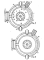
- the tuning fork 6 can be mounted at a single fixing point 7, as shown in Figure 3, or it can be mounted through two nodes 40 and 41 - this modification is as shown in Figure 4. Alternatively, the tuning fork 6 can be firmly clamped at a node position to the base 9, although this variant is not illustrated.
- FIG. 5 A further modification is shown in Figure 5 in which two tuning forks 50 and 51 are provided which together constitute the outer cylindrical wall of the co-axial cavity.
- the ends of the tines 52, 53 adjacent to the output port 17 are connected thereto by flexible connections 18 as previously, but the other two tines 54 and 55 are electrically coupled by means of a flexible bridge 56 of conductive material.
- These flexible portions serve both to conduct the microwave currents circulating around the cavity, and to mechanically couple the tuning forks. Both tuning forks are carefully matched so that they exhibit exactly the same resonant frequency, and the provision of the bridge 56 constrains the two tuning forks 50, 51 to vibrate in step with each other.
- Each tuning fork 50 and 51 enables the dimensions of the co-axial cavity 1 to approximate more closely to a circular cross-section, in that the symmetry of the cavity profile is maintained over the frequency tuning range to a greater extent.
- Each tuning fork 50 and 51 is provided with its own drive unit 57 and 58, and with its own transducer 59 and 60 from which the instantaneous frequency of resonance can be determined.
- the symmetry of the shape of the co-axial cavity can be further enhanced by the provision of a greater number of tuning forks positioned regularly around the outer walls of the cavity.
- a thin band of thin metal such as copper which has a very good electrical conductivity could be mounted inside the tuning forks so that the ends of the band are connected only to the tips of the tuning fork, but do not otherwise contact it.
- Such an arrangement is shown in Figure 6 and the shapes of the tines of the tuning forks are modified slightly from that shown in Figure 5 so that the flexible band adopts an almost perfectly symmetrical circular profile.
- the diameter of the cylinder constituted by the band will increase and decrease accordingly, but its profile will remain substantially the same, thereby minimising the distortion which is present in the output microwave signal generated by the magnetron.
Landscapes
- Microwave Tubes (AREA)
- Constitution Of High-Frequency Heating (AREA)
- Control Of High-Frequency Heating Circuits (AREA)
- Stabilization Of Oscillater, Synchronisation, Frequency Synthesizers (AREA)
Abstract
Description
- This invention relates to magnetrons. A magnetron produces a microwave output signal whose frequency is primarily dependent on the frequency characteristics of a resonant chamber associated with the magnetron. By altering the electrical properties of the chamber, the frequency of oscillation of the magnetron can be adjusted and this is often necessary to provide fine tuning of its output frequency. It is sometimes desirable to sweep the frequency of resonance periodically over a predetermined frequency range, but it is difficult to obtain fast sweep rates since the mechanical actuators and linkages usually necessary to produce an alteration of the electrical properties of the resonator exhibit a relatively great mechanical inertia.
- It has been proposed to overcome these difficulties by using a tuning fork to vibrate one, or possibly both, of the end plates of the resonant chamber, and such an arrangement is described in our earlier patent application EP-A-0 012 039. The present invention seeks to provide an improved magnetron which is capable of superior operating performance.
- According to this invention, a co-axial magnetron includes an evacuated housing which contains within it an annular resonant cavity which surrounds a cathode and which determines the frequency of oscillation of a microwave signal generated by the magnetron; tuning fork means mounted within the evacuated housing and operative to induce vibratory motion in the outer cylindrical walls of said annular resonant cavity so as to cyclically alter its resonant frequency, the inner cylindrical surfaces of the tines of the tuning fork means having a substantially circular base and following the shape of the annular resonant cavity; and means responsive to the movement of the outer cylindrical walls for generating a signal representative of the instantaneous frequency of the cavity.
- The tuning fork means can itself constitute the whole or part of the outer cylindrical walls of the annular resonant cavity, or instead the tines of the tuning fork means can be coupled to thin flexible material of general cylindrical form which constitutes the outer walls of the cavity. In either case, the mean cross-sectional shape of the cavity may not be exactly circular and the departure of the shape from a true circle which occurs as the walls are vibrated can be minimised by the use of more than one tuning fork means arranged around the outer walls of the cavity. In order to determine the instantaneous resonant frequency of the cavity, the movement of the walls or the movement of the tines of the tuning fork can be monitored, whichever is the more convenient.
- The invention is further described by way of example with reference to the accompanying drawings, in which
- Figure 1 shows a section view of a co-axial magnetron in accordance with the present invention,
- Figure 2 shows a perspective view of a tuning fork which forms part of the co-axial cavity of the magnetron,
- Figure 3 is a plan section view of the same magnetron taken on line XY of Figure 1, and
- Figures 4, 5 and 6 show alternative modifications to Figure 3.
- Referring to Figures 1, 2 and 3, a co-axial magnetron consists of an
annular cavity 1 which surrounds anelongate cathode 2 and aninteraction space 3 consisting of a large number of individual cavities which are spaced apart by anode vanes positioned around thecathode 2. These cavities constitute the anode structure, and a magnetic field is produced within theinteraction space 3 by means ofmagnets 4 and 5. Theannular cavity 1 is formed by a pair of general cylindrical walls, theinner surface 30 of which is constituted by the anode structure and theouter surface 31 of which is constituted by one face of atuning fork 6, which is firmly mounted at itsbase 7 to a rigidouter housing 8 which constitutes an evacuated envelope. Thebase 9 of thehousing 8 constitutes one end plate of thecavity 1, and the opposite end plate of the cavity is constituted by a movableannular ring 10. - The
base 9, thering 10 and thetuning fork 6 are made of a robust material which is suited to the mechanical functions which they have to provide, whilst the faces of these bodies which constitute thecavity 1 itself are copper plated to ensure good electrical conductivity. - In operation, electrons are emitted by the
cathode 2 into theinteraction space 3 when a high voltage, usually in pulse form, is applied between the cathode and the anode structure. The electrons set up microwave oscillations under the influence of the magnetic field and under the influence of the very high electric field which exists between the anode walls of theinteraction space 3 and thecathode 2. The resonant frequency is determined by the electrical properties of theinteraction space 3 and by the resonant frequency of theannular cavity 1 The resonant frequency of theannular cavity 1 is determined by the physical dimensions of thewalls end plate 10 or by moving thecylindrical wall 31 of thetuning fork 6, the resonant frequency can be altered. - The
outer cavity wall 31 is constituted by thetuning fork 6 which is mounted, as previously described, to thehousing 8 at itsbase 7. Thetuning fork 6 consists of twotines drive unit 13, which consists of an electromagnet which acts upon an iron ormagnetic body 14 mounted on thetine 11. Thedrive unit 13 is arranged to operate at the resonant frequency of thetuning fork 6 so as to impart the energy to it which is necessary for it to maintain oscillation. The mode of vibration is as represented by the arrows A shown in Figure 2, and the effect is to cyclically increase and decrease the outer diameter of the co-axial cavity 1 - in practice theouter surface 31 is likely to depart slightly from that of a true cylinder during the course of the cyclic movement. The actual frequency of vibration of the tuning fork is determined almost wholly by the mechanical properties and dimensions of the tuning fork itself. One of the most important properties of a tuning fork is that it is very sharply resonant at a predetermined frequency, and that it is unable to maintain vibration at frequencies which depart significantly from the resonant value. Thetuning fork 6 is made in the form of two eccentric cylindrical surfaces, theinner surface 31 constituting the outer cylindrical wall of theco-axial cavity 1, and the outercylindrical surface 15 of thetuning fork 6 having an axis which is displaced from that of the innercylindrical surface 31 so as to give the increased thickness required at thebase 7, and to allow thetines - As the
tuning fork 6 is vibrated so the resonant frequency of the cavity changes accordingly in a cyclic manner as previously described. When a pulse of electrical energy is applied to the magnetron, an output microwave signal is generated having a frequency which is determined by the instantaneous position of thetines gap 16 between the adjacent open ends of thetines output port 17. To maintain the electrical properties of the output port, a thin flexible connection of electricallyconductive material 18 is provided to connect the respective end edges of thetines output port 17 itself. An electricallytransmissive window 19 is arranged within theoutput port 17 to allow the microwave energy to pass through without significant attenuation, but to preserve the vacuum within the body of the magnetron. The interior of thehousing 8 is maintained at a very high level of vacuum, since only under this condition is the magnetron an efficient generator of microwave energy. - In order that the instantaneous resonant frequency of the
cavity 1 can be accurately monitored eachtine magnetic transducer 21, which are both mounted in the wall of thehousing 8. A small piece of iron ormagnet tine magnetic transducers 21 from which an output signal can be taken which is representative of the velocity of the tine at any instant. From a knowledge of the resonant properties of thetuning fork 6, the instantaneous frequency of the cavity can thus be determined. - The use of the tuning fork thus enables the magnetron to be operated in a frequency agile mode, that is to say, successive pulses of microwave energy can be generated at different predetermined frequencies which lies within the band represented by the maximum and minimum sizes of the
resonant cavity 1 defined by the extent of the vibratory movement of thetines - When the
tuning fork 6 is in its normal mode of operation in which its two tines are in anti-phase, the mechanical losses and coupling to theouter housing 8 are very small. The power required by thedrive unit 13 is very small and the oscillation is insensitive to vibrations of the magnetron. Any translational movement of thetuning fork 6 caused by the application or shock or large amplitude vibration to the magnetron as a whole causes a similar (i.e. in-phase) displacement of both tines, so that overall the resonant frequency is not adversely affected to any significant extent. Since the magnetron frequency is substantially independent of any in-phase tuning fork movement, thetransducers tines - The
tuning fork 6 can be mounted at asingle fixing point 7, as shown in Figure 3, or it can be mounted through two nodes 40 and 41 - this modification is as shown in Figure 4. Alternatively, thetuning fork 6 can be firmly clamped at a node position to thebase 9, although this variant is not illustrated. - A further modification is shown in Figure 5 in which two
tuning forks tines output port 17 are connected thereto byflexible connections 18 as previously, but the other twotines flexible bridge 56 of conductive material. These flexible portions serve both to conduct the microwave currents circulating around the cavity, and to mechanically couple the tuning forks. Both tuning forks are carefully matched so that they exhibit exactly the same resonant frequency, and the provision of thebridge 56 constrains the twotuning forks tuning forks co-axial cavity 1 to approximate more closely to a circular cross-section, in that the symmetry of the cavity profile is maintained over the frequency tuning range to a greater extent. Eachtuning fork own drive unit own transducer - The symmetry of the shape of the co-axial cavity can be further enhanced by the provision of a greater number of tuning forks positioned regularly around the outer walls of the cavity. Instead of allowing the inner surface of the tines to themselves constitute the cavity walls, a thin band of thin metal such as copper which has a very good electrical conductivity could be mounted inside the tuning forks so that the ends of the band are connected only to the tips of the tuning fork, but do not otherwise contact it. Such an arrangement is shown in Figure 6 and the shapes of the tines of the tuning forks are modified slightly from that shown in Figure 5 so that the flexible band adopts an almost perfectly symmetrical circular profile. As the ends of the tines vibrate, the diameter of the cylinder constituted by the band will increase and decrease accordingly, but its profile will remain substantially the same, thereby minimising the distortion which is present in the output microwave signal generated by the magnetron.
Claims (8)
Priority Applications (1)
| Application Number | Priority Date | Filing Date | Title |
|---|---|---|---|
| AT82303999T ATE19326T1 (en) | 1981-09-08 | 1982-07-29 | MAGNETRONS. |
Applications Claiming Priority (2)
| Application Number | Priority Date | Filing Date | Title |
|---|---|---|---|
| GB08127125A GB2106309B (en) | 1981-09-08 | 1981-09-08 | Cyclic turning of magnetrons |
| GB8127125 | 1981-09-08 |
Publications (2)
| Publication Number | Publication Date |
|---|---|
| EP0074173A1 EP0074173A1 (en) | 1983-03-16 |
| EP0074173B1 true EP0074173B1 (en) | 1986-04-16 |
Family
ID=10524369
Family Applications (1)
| Application Number | Title | Priority Date | Filing Date |
|---|---|---|---|
| EP82303999A Expired EP0074173B1 (en) | 1981-09-08 | 1982-07-29 | Improvements in or relating to magnetrons |
Country Status (5)
| Country | Link |
|---|---|
| US (1) | US4518932A (en) |
| EP (1) | EP0074173B1 (en) |
| AT (1) | ATE19326T1 (en) |
| DE (1) | DE3270616D1 (en) |
| GB (1) | GB2106309B (en) |
Families Citing this family (12)
| Publication number | Priority date | Publication date | Assignee | Title |
|---|---|---|---|---|
| GB2200242B (en) * | 1987-01-21 | 1990-10-24 | English Electric Valve Co Ltd | Magnetrons |
| US5159241A (en) * | 1990-10-25 | 1992-10-27 | General Dynamics Corporation Air Defense Systems Division | Single body relativistic magnetron |
| US5162698A (en) * | 1990-12-21 | 1992-11-10 | General Dynamics Corporation Air Defense Systems Div. | Cascaded relativistic magnetron |
| US6607920B2 (en) | 2001-01-31 | 2003-08-19 | Cem Corporation | Attenuator system for microwave-assisted chemical synthesis |
| US6753517B2 (en) | 2001-01-31 | 2004-06-22 | Cem Corporation | Microwave-assisted chemical synthesis instrument with fixed tuning |
| US6886408B2 (en) * | 2001-01-31 | 2005-05-03 | Cem Corporation | Pressure measurement in microwave-assisted chemical synthesis |
| US7144739B2 (en) * | 2002-11-26 | 2006-12-05 | Cem Corporation | Pressure measurement and relief for microwave-assisted chemical reactions |
| US7034266B1 (en) | 2005-04-27 | 2006-04-25 | Kimberly-Clark Worldwide, Inc. | Tunable microwave apparatus |
| US9844101B2 (en) * | 2013-12-20 | 2017-12-12 | Scp Science | System and method for uniform microwave heating |
| CN106531598B (en) * | 2016-11-07 | 2018-01-30 | 中国人民解放军国防科学技术大学 | Can mechanical frequency modulation L-band transit-time oscillator |
| CN107946157A (en) * | 2017-12-31 | 2018-04-20 | 中国电子科技集团公司第十二研究所 | The microwave frequency micromatic setting and coaxial manetron of a kind of coaxial manetron |
| CN110927066B (en) * | 2019-12-12 | 2022-04-12 | 哈尔滨工业大学 | Device and method for improving the performance of photoacoustic spectroscopy sensor based on H-shaped resonant tube |
Family Cites Families (10)
| Publication number | Priority date | Publication date | Assignee | Title |
|---|---|---|---|---|
| BE467809A (en) * | 1940-10-08 | |||
| GB576485A (en) * | 1942-11-13 | 1946-04-05 | Patelhold Patentverwertung | Means for tuning magnetrons |
| GB785642A (en) * | 1953-08-01 | 1957-10-30 | Emi Ltd | Improvements in or relating to cavity resonators |
| US3087124A (en) * | 1958-05-29 | 1963-04-23 | Raytheon Co | Feedback system for reed modulated magnetrons |
| US3727099A (en) * | 1963-02-04 | 1973-04-10 | Westinghouse Electric Corp | Tuned cavity device |
| US3440565A (en) * | 1966-03-17 | 1969-04-22 | Westinghouse Electric Corp | Sensor for detection of frequency of a reed modulated magnetron |
| DE1591392B2 (en) * | 1967-12-16 | 1970-03-12 | Philips Patentverwaltung Gmbh, 2000 Hamburg | Arrangement for tuning the resonance frequency of a coaxial line circuit, especially for single or multi-chamber klystron |
| US3731137A (en) * | 1972-02-03 | 1973-05-01 | Raytheon Co | Coaxial magnetron |
| GB1516504A (en) * | 1975-07-02 | 1978-07-05 | English Electric Valve Co Ltd | Cavity magnetrons |
| GB2036418B (en) * | 1978-12-05 | 1983-01-19 | English Electric Valve Co Ltd | Magnetrons |
-
1981
- 1981-09-08 GB GB08127125A patent/GB2106309B/en not_active Expired
-
1982
- 1982-07-29 AT AT82303999T patent/ATE19326T1/en not_active IP Right Cessation
- 1982-07-29 DE DE8282303999T patent/DE3270616D1/en not_active Expired
- 1982-07-29 EP EP82303999A patent/EP0074173B1/en not_active Expired
- 1982-08-10 US US06/407,274 patent/US4518932A/en not_active Expired - Fee Related
Also Published As
| Publication number | Publication date |
|---|---|
| GB2106309A (en) | 1983-04-07 |
| US4518932A (en) | 1985-05-21 |
| DE3270616D1 (en) | 1986-05-22 |
| ATE19326T1 (en) | 1986-05-15 |
| EP0074173A1 (en) | 1983-03-16 |
| GB2106309B (en) | 1985-06-05 |
Similar Documents
| Publication | Publication Date | Title |
|---|---|---|
| US4518932A (en) | Coaxial magnetron having cavity walls vibrated by tuning fork | |
| US4321500A (en) | Longitudinal isolation system for flexurally vibrating force transducers | |
| US2411953A (en) | Electron discharge device of the magnetron type | |
| US3731137A (en) | Coaxial magnetron | |
| US3412285A (en) | Coaxial magnetron with rotatable tuning means | |
| GB605300A (en) | Improvements in or relating to electrical resonance chambers | |
| US4311968A (en) | Magnetron having cavity wall vibrated by tuning fork | |
| US2589885A (en) | Tunable magnetron | |
| US3967155A (en) | Electronic frequency tuning magnetron | |
| US2548808A (en) | Continuous-strip anode for magnetrons | |
| US4331935A (en) | Tuning apparatus for a radio frequency power device | |
| US2489298A (en) | Velocity modulation electron discharge device | |
| US4277723A (en) | Symmetrical magnetron with output means on center axis | |
| US3914644A (en) | Rotary tuner for circular electric mode crossed field tube | |
| US2527699A (en) | Tunable oscillator | |
| US3334266A (en) | Coaxial output line for a magnetron | |
| EP0279112B1 (en) | Tunable magnetrons | |
| US4636749A (en) | Pulsed magnetron tube having improved electron emitter assembly | |
| US2419121A (en) | Tuning means for cavity resonators | |
| US2624862A (en) | Tunable strapped magnetron | |
| US2615156A (en) | Frequency modulation of electron discharge devices | |
| US2582045A (en) | Tunable velocity modulated electron discharge device | |
| JPH10241585A (en) | Flat magnetron | |
| US3166696A (en) | Vibrating capacitor | |
| US2680229A (en) | Frequency-modulated generator |
Legal Events
| Date | Code | Title | Description |
|---|---|---|---|
| PUAI | Public reference made under article 153(3) epc to a published international application that has entered the european phase |
Free format text: ORIGINAL CODE: 0009012 |
|
| AK | Designated contracting states |
Designated state(s): AT BE CH DE FR IT LI LU NL SE |
|
| 17P | Request for examination filed |
Effective date: 19830725 |
|
| GRAA | (expected) grant |
Free format text: ORIGINAL CODE: 0009210 |
|
| AK | Designated contracting states |
Kind code of ref document: B1 Designated state(s): AT BE CH DE FR IT LI LU NL SE |
|
| PG25 | Lapsed in a contracting state [announced via postgrant information from national office to epo] |
Ref country code: LI Effective date: 19860416 Ref country code: CH Effective date: 19860416 Ref country code: BE Effective date: 19860416 Ref country code: AT Effective date: 19860416 |
|
| REF | Corresponds to: |
Ref document number: 19326 Country of ref document: AT Date of ref document: 19860515 Kind code of ref document: T |
|
| PG25 | Lapsed in a contracting state [announced via postgrant information from national office to epo] |
Ref country code: SE Effective date: 19860430 |
|
| ITF | It: translation for a ep patent filed | ||
| REF | Corresponds to: |
Ref document number: 3270616 Country of ref document: DE Date of ref document: 19860522 |
|
| ET | Fr: translation filed | ||
| PG25 | Lapsed in a contracting state [announced via postgrant information from national office to epo] |
Ref country code: LU Free format text: LAPSE BECAUSE OF NON-PAYMENT OF DUE FEES Effective date: 19860731 |
|
| REG | Reference to a national code |
Ref country code: CH Ref legal event code: PL |
|
| PLBE | No opposition filed within time limit |
Free format text: ORIGINAL CODE: 0009261 |
|
| STAA | Information on the status of an ep patent application or granted ep patent |
Free format text: STATUS: NO OPPOSITION FILED WITHIN TIME LIMIT |
|
| 26N | No opposition filed | ||
| PGFP | Annual fee paid to national office [announced via postgrant information from national office to epo] |
Ref country code: NL Payment date: 19870731 Year of fee payment: 6 |
|
| PGFP | Annual fee paid to national office [announced via postgrant information from national office to epo] |
Ref country code: FR Payment date: 19890609 Year of fee payment: 8 |
|
| PGFP | Annual fee paid to national office [announced via postgrant information from national office to epo] |
Ref country code: DE Payment date: 19890911 Year of fee payment: 8 |
|
| PG25 | Lapsed in a contracting state [announced via postgrant information from national office to epo] |
Ref country code: NL Effective date: 19900201 |
|
| NLV4 | Nl: lapsed or anulled due to non-payment of the annual fee | ||
| PG25 | Lapsed in a contracting state [announced via postgrant information from national office to epo] |
Ref country code: FR Effective date: 19910329 |
|
| PG25 | Lapsed in a contracting state [announced via postgrant information from national office to epo] |
Ref country code: DE Effective date: 19910403 |
|
| REG | Reference to a national code |
Ref country code: FR Ref legal event code: ST |