EP0074115B1 - Off-axis light beam defect detector - Google Patents
Off-axis light beam defect detector Download PDFInfo
- Publication number
- EP0074115B1 EP0074115B1 EP82108229A EP82108229A EP0074115B1 EP 0074115 B1 EP0074115 B1 EP 0074115B1 EP 82108229 A EP82108229 A EP 82108229A EP 82108229 A EP82108229 A EP 82108229A EP 0074115 B1 EP0074115 B1 EP 0074115B1
- Authority
- EP
- European Patent Office
- Prior art keywords
- lens
- light
- reflected
- disc
- light beam
- Prior art date
- Legal status (The legal status is an assumption and is not a legal conclusion. Google has not performed a legal analysis and makes no representation as to the accuracy of the status listed.)
- Expired
Links
Images

Classifications
-
- G—PHYSICS
- G01—MEASURING; TESTING
- G01B—MEASURING LENGTH, THICKNESS OR SIMILAR LINEAR DIMENSIONS; MEASURING ANGLES; MEASURING AREAS; MEASURING IRREGULARITIES OF SURFACES OR CONTOURS
- G01B11/00—Measuring arrangements characterised by the use of optical techniques
- G01B11/16—Measuring arrangements characterised by the use of optical techniques for measuring the deformation in a solid, e.g. optical strain gauge
-
- G—PHYSICS
- G11—INFORMATION STORAGE
- G11B—INFORMATION STORAGE BASED ON RELATIVE MOVEMENT BETWEEN RECORD CARRIER AND TRANSDUCER
- G11B7/00—Recording or reproducing by optical means, e.g. recording using a thermal beam of optical radiation by modifying optical properties or the physical structure, reproducing using an optical beam at lower power by sensing optical properties; Record carriers therefor
- G11B7/002—Recording, reproducing or erasing systems characterised by the shape or form of the carrier
- G11B7/0037—Recording, reproducing or erasing systems characterised by the shape or form of the carrier with discs
-
- G—PHYSICS
- G01—MEASURING; TESTING
- G01N—INVESTIGATING OR ANALYSING MATERIALS BY DETERMINING THEIR CHEMICAL OR PHYSICAL PROPERTIES
- G01N21/00—Investigating or analysing materials by the use of optical means, i.e. using sub-millimetre waves, infrared, visible or ultraviolet light
- G01N21/84—Systems specially adapted for particular applications
- G01N21/88—Investigating the presence of flaws or contamination
- G01N21/95—Investigating the presence of flaws or contamination characterised by the material or shape of the object to be examined
- G01N21/9506—Optical discs
-
- G—PHYSICS
- G01—MEASURING; TESTING
- G01N—INVESTIGATING OR ANALYSING MATERIALS BY DETERMINING THEIR CHEMICAL OR PHYSICAL PROPERTIES
- G01N21/00—Investigating or analysing materials by the use of optical means, i.e. using sub-millimetre waves, infrared, visible or ultraviolet light
- G01N21/17—Systems in which incident light is modified in accordance with the properties of the material investigated
- G01N21/55—Specular reflectivity
Definitions
- the present invention relates to light beam scanning apparatus, and more particularly relates to apparatus for detecting defects in information discs such as optical discs.
- An optical disc is a clear plastic disc approximately the size of a standard LP phonograph record, which has a thin reflective layer imbedded in its interior.
- the reflective layer is provided with a spiral-shaped information track in the form of a series of spaced-apart indicia, such as pits or holes, which can be "read" by a focused laser beam by directing the focused spot of the laser beam along the spiral-shaped track and detecting the variations in the intensity of the light reflected therefrom as the spot encounters alternately indicia and the reflective surface between the indicia.
- indicia are holes
- the size and spacing of the indicia, and the spacing of adjacent spiral tracks in a typical optical disc are extremely small, being of the order of magnitude of approximately one micron.
- the reading laser In order to "read" the information contained in the indicia of such extremely small dimensions, the reading laser must be focused to an extremely small spot, being also of the order of magnitude of one micron.
- Hole-type indicia can be formed in the reflective layer by means of a high intensity "writing" laser which is focused onto the layer and turned on and off as it is directed across the disc in spiral fashion.
- writing laser When the writing laser is turned on, it causes a hole to form in the reflective layer where it is focused, and when it is turned off it leaves the layer unaffected.
- Information can be imparted to the track by controlling the length and spacing of the holes.
- the reflected tight of the reading laser is directed to a photo detector where the variation in intensity of the light incident on the photo detector due to the presence and absence of indicia in the reading track cause the output signal of the photo detector to take the form of a series of pulses.
- the length and spacing in time of these pulses correspond to the length and spacing of the indicia on the optical disc, and in this way the recorded information is recovered.
- the player apparatus disclosed in U.S. Patent 4,332,022 is designed especially to play video optical discs that contain video information for storage and playback of television program material.
- the technique disclosed therein for maintaining the focus of the spot of laser light on the disc involves the provision of a separate beam of laser light substantially parallel to the reading laser light beam.
- This separate laser beam is focused onto the disc by the same optical system used to focus the read beam.
- the light of the separate laser beam is reflected off of the laser disc and directed to a special photo detector which detects the size of the beam incident thereon and provides an output signal indicative of the state of focus of the separate light beam.
- This output signal is used in a focus servo mechanism to maintain the separate beam in a focused condition even if the disc is warped. This also maintains the read beam in focus.
- Such a focus servo system is used in writing apparatus as well.
- U.S. Patent 4,030,835 describes a method and arrangement _for detecting defects in a spiral groove used to store information. For that aim the surface of a video disk is scanned by a laser beam with a relatively large diameter and oblique angle of incidence. The optical grating formed by the grooves arranged close to each other diffracts the beam to detector means if the illuminated area is defect free, otherwise the diffracted light is displaced and the detector output changes.
- This method permits a rapid scan of the disk for defects; there is, however, no practical possibility to integrate the oblique test beam into existing playback or recording machines. Thus, video information contained in an area indicated as defect cannot be displayed immediately during the test to assess the effects of the defect on video playback quality.
- optical discs having defects can be used to store computer data for retrieval if the location and size of defects can be accurately determined in conjunction with an apparatus for storing the information on the disc.
- defect detecting apparatus which provides accurate identification of the location and size of defects in optical discs. Further, there is a need for a defect detector apparatus which provides accurate detection of defects in conjunction with a laser writing function for an optical disc to permit the precise localization of the writing laser beam in advance of the defective area.
- the present invention fulfills the aforementioned needs.
- the present invention is embodied in a beam- scanning apparatus for detecting a property of a light beam reflected off of a surface to be scanned, which may be used in connection with another light beam scanning apparatus, for example, by way of retrofit to an existing apparatus.
- a focusing, or objective lens disposed above a surface to be scanned and means for maintaining a substantially fixed distance between the focusing lens and the scanning surface.
- scanning means for providing lateral movement between the lens and the surface.
- a light beam source is provided arranged to provide a light beam which is off-axis with respect to the central axis of the lens, wherein the light beam is directed to pass through the lens to the scanned surface.
- a light beam sensing element is positioned so as to detect that portion of the light beam reflected off of the surface and transmitted back through the lens.
- the scanning apparatus of the present invention is especially adaptable for use in connection with a video disc playback apparatus.
- Such playback apparatus typically includes a laser beam servo system for maintaining a focusing lens in a substantially fixed relationship with respect to a video disc being read.
- the apparatus of the present invention may be easily retrofitted to such video disc playback machine so as to use the focusing lens already provided in the system as well as other optical elements provided in the apparatus such as mirrors, quarter wavelength plates, and. beam splitters to provide an accurate and rapid defect detecting function with respect to a video optical disc. The player may be quickly directed to the detected defective area for playback over the area to determine if the area provides acceptable playback.
- Another use to which the apparatus of the present invention is especially adapted is in connection with a digital data recording apparatus to permit the accurate detection of the size and location of defects in the recording medium surface so that in response thereto, the recording of data in the areas where defects have been detected can be inhibited, and appropriate flag codes can be provided in the information track which informs the digital data reading machine not to look for data as it passes over the defective location.
- a small particle of contaminating material 22 is present in the adhesive layer 16 between the parts 12, 14.
- Such a particle can be introduced in the manufacturing process in a number of ways, for example, if a dust particle lands on the adhesive prior to the bonding together of the disc parts.
- the presence of the particle 22 results in an inclusion which causes bulging areas 24, 26 of the reflective layers 18, 20. If the slope of the sides of such a bulge is great enough the focused servo system cannot maintain focus in the vicinity of the bulge and the aforementioned problems arise.
- Other kinds of defects causing similar sloped surfaces in the reflective layers 18, 20 may also be present in the disc 10.
- a laser 30 provides a polarized laser light beam output 32 which is directed to a mirror 34 where it is reflected to pass through a polarizing beam splitter 36.
- the light beam then passes through a quarter wavelength plate 38 before being reflected off of the surface 18, which is made to move laterally with respect to the beam 32.
- the incident beam 32 is directed perpendicularly with respect to the plane of the surface 18. Therefore, if the surface 18 contains no irregularities, the reflected beam 42 will be directed back along the same path to the polarizing beam splitter 36 after passing again through the quarter wavelength plate 38. After thus passing twice through the quarter wavelength plate 38, the light beam 42 is rotated 90° with respect to the incident light beam 32. Therefore, substantially all of the reflected light beam 42 will be reflected by the beam splitter 36 as shown.
- the sides of the defect present a reflective surface which is oriented at an angle with respect to the plane of the reflective surface 18. Consequently, when the incident beam 32 of the apparatus of Figure 2 encounters such a defect it is not reflected back along the same path, but rather it is reflected at some angle with respect to the incident path.
- a beam 42' is reflected off of the beam splitter 36 in a different direction.
- a position-sensitive photo detector 44 is placed along the path of the light beams 42, 42' reflected off of the beam splitter 36 and a signal is derived which is representative of the displacement x of the reflected beam 42'. Since the distance of x shown in Figure 3 corresponds geometrically to the angle D of the reflected beam 42' with respect to the reflected beam 32 the output signal of the photodetector provides a measure of the presence of a defect.
- such an apparatus is not readily adaptable to provide a spot of light for defect detection close enough to the "read" laser spot or "write” laser spot in a reading or recording apparatus for desired accuracy of detection of defect location and size with respect to the primary (reading or writing) laser spot.
- the objective lens and objective lens motion assembly used in the focus servo system are relatively large and must be placed close to the disc; a typical objective lens is about 8 mm in diameter and typically rides approximately 3 mm above the surface of the disc.
- the objective lens motion assembly surrounds the lens, further extending the diameter of the arrangement.
- FIG. 3 of the drawings shows in block diagram form the preferred embodiment of the present invention.
- a standard video disc player apparatus has been modified to include the off-axis light beam defect detector of the present invention.
- a first laser beam source 50 is provided which emits a polarized beam of coherent light 52.
- This beam of light 52 is reflected off of mirrors 54 and 56 through a defraction grating 58 and beam diverting lens 60 to a polarization beam splitter 62.
- the polarization of the light beam 52 is oriented so that a substantial portion of the beam passes through the beam splitter.
- the laser light 52 which passes through the beam splitter 62 is directed through a quarter wavelength plate 64 to a further mirror 66 where it is directed to an objective lens 68.
- the objective lens 68 focuses the diverging beam of laser light 52 to a spot 70 on the surface of a video disc 10.
- the video disc 10 is clamped to a spindle 74 which is rotated at high speeds by a spindle drive system 75 so that, in conjunction with a linear tracking mechanism associated with the objective lens (not shown) a spiral tracking function may be effected for the spot 70 of laser light on the disc 72, as is well known in the art.
- the light 52 is reflected back from the disc through the objective lens 68 where it is reflected off of mirror 66 and directed back through quarter wavelength plate 64 to the polarizing beam splitter 52.
- the reflected light directed to the beam splitter 62 passes through the quarter wavelength plate 64 twice the direction of polarization is rotated by 90° with respect to the incident light 52. Therefore, a substantial portion of the reflected light will be reflected by the beam splitter 62 at right angles to the central axis of the incident light beam due to the orientation of the surface of the beam splitter 62 as shown.
- a focusing lens 76 is placed in the path of the light which has been reflected by the beam splitter 62 to focus that light onto a photodetector 78.
- the photodetector 78 may be arranged so as to provide an output signal representative of the state of focus of the spot 70 of light with respect to the video disc 10.
- Such output signal may be provided on a signal line 80 to a servo control mechanism 82 which, in response to the signal on line 80 maintains a relative spacing between the objective lens 68 and the disc 10 so as to maintain the spot of light 70 in focus on the reflective surface of the disc 10.
- a second laser light beam source 84 which emits a second, auxiliary polarized laser light beam 86.
- This second beam 86 passes through an auxiliary light beam focusing lens 88 to mirrors 90 and 92 which direct the auxiliary laser light beam 86 through the polarizing beam splitter 62 so as to pass through the quarter wavelength plate 64.
- This beam then passes to the mirror 66 which directs the beam 86 through the objective lens 68 which focuses the beam 86 to a second spot 94 on the surface of the video disc 10.
- the light from the auxiliary beam 86 reflected off of the video disc 10 passes back through the objective lens 68 and is reflected by mirror 66 through the quarter wavelength plate 64 to the polarizing beam splitter 62.
- a mirror 98 is placed in the path of the reflected light beam 96 which directs the light beam 96 to a photodetector subsystem 100.
- FIG. 4 a simplified diagram is shown of the objective lens 68 and the video disc 10.
- the incident auxiliary beam of laser light 52 converges due to the focusing action of the auxiliary beam focusing lens 88 (Fig. 3) to a focal point 102 which, by appropriate selection and arrangement of the focusing lens 88, using well-known techniques, is made to coincide with the focal point f of the objective lens 68 on the opposite side of the lens 68 from the video disc 10.
- This causes the light beam 52 which emerges from the objective lens 68 to be a collimated beam of light parallel with the central axis of the lens.
- the incident light beam 52 will be reflected off of the disc 10 and be directed back along the same path as the incident beam.
- the light beam 52 represents both the incident and the reflected light beam from a completely flat surface.
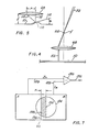
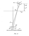
- FIG. 5 a simplified diagram of the objective lens 68 and the surface of the video disc 10 is shown in connection with the presence of a defect 110 shown greatly enlarged as to scale for the purposes of clarity of description. Also for purposes of clarity, light beams are depicted as single lines.
- the light beam 52 is incident on the sloping side surface of the defect 110.
- the tangent of the surface of the defect 110 is depicted by line 112 which makes an angle r with respect to the flat surface of the disc 10.
- the reflected beam 114 forms an angle of 2r with respect to the incident light beam 52.
- the lateral deflection "r" of the light beam at the pupil plane of the objective lens 6 is given by: where s is equal to the distance of the pupil plane of the objective lens 68 from the surface of the video disc 62.
- a representative value of s for a conventional video disc player is approximately 8.2 mm. For such a configuration,
- Figure 6 is a schematic diagram showing the relationship between the objective lens 68, the surface of the video disc 10, and the photodetector subsystem 100.
- the beam of reflective light 114 is shown deflected by the distance r at the objective lens 68, as described above in connection with Figure 5.
- the path of the reflected light beam 114 in the case where no defect is present and reflection is normal to the reflective surface of the disc 10 is also shown for reference.
- the reflected beam 114 and 114' converge on a point 116 located at the back image plate 118 of the objective lens 68.
- the beams then diverge and impinge on the photodetector subsystem 100, as shown.
- the photodetector subsystem 100 is located a distance 1 from the back image plane 118, as shown by arrow 120. This distance 1 is equal to the long conjugate of the objective lens 68.
- the photodetector subsystem 100 is located at this distance from the back image plane 118, it is in a 1:1 conjugate relationship with the lens and, consequently, any lateral deflection r at the objective lens 68 due to deflection of the reflected light beam 114 will give rise to a corresponding lateral deflection r of the incident light beam 114 on the photodetector subsystem 100, as shown.
- FIG. 7 is a schematic diagram of the photodetector subsystem 100 shown in Figure 3.
- a split (bi-cell) photodetector 100 is provided, having a left cell A and a right cell B.
- This photodetector 100 may be a quadrature photodetector having each of the left and right quadrant cells connected together electrically to provide a split cell function. This permits measurement of the lateral deviation of the light beam incident on the photodetector 100 in one direction. In the preferred embodiment, lateral deflections of the light beam 114 corresponding to defect slopes in the tangential direction are detected, while defect slopes in the radial direction are not detected.
- the circular boundary 124 of a spot of light incident on the photo cell 100 is shown, off-set by the distance r from the line of separation between Cell A and Cell B. It will be recalled that the distance r represents the lateral deviation of the reflected beam of light at the pupil plane of the objective lens 68, described above in connection with Figure 5. It will also be appreciated that small spots of light do not have well defined boundaries due to defraction and other effects. Following convention, it will be assumed that the circular boundary 124 represents the 1/e z light intensity boundary of a spot of light.
- spot 94 may be located on the disc 10 wherever desired with respect to the spot 70 of the first laser beam, limited by the field of view of the objective lens 68 and the radial dimensions of the first laser beam 52 at the location of the deflecting mirror 92.
- This radial dimension may be made to be quite small by placing the deflecting mirror 90 close to the focal point of the diverging lens 60 where the radial dimensions of the laser beam 52 reach a minimum.
- the placement of the deflecting mirror 92 is adjusted so that the center of the auxiliary laser beam spot 94 is located at a distance of approximately .1 to .2 mm from the spot 70 of the first laser beam 52 radially in the direction of forward reading of the first laser beam 52.
- the center of the spot 94 is spaced approximately .15 mm from the center of spot 70 in the radial direction and toward the outside of the disc.
- the ratio of the focal lengths of the auxiliary beam converging lens 88 to the objective lens 68 in the preferred embodiment of the present invention is selected, according to well-known principles, to produce a spot 94 having a diameter of approximately 80 microns. It has been found that the combination of a spot diameter of 80 microns and a radial spacing of approximately .15 mm between the spots 70 and 94, as described above, permits the video disc 10 to be read rapidly in a "fast scan mode" and, upon the detection of a defect, the video disc player can automatically switched to a "read mode" without the necessity of backing' up the objective lens. The previously detected defect area may then simply be read by the first laser spot 70 and the video picture viewed to determine if the defect gives rise to acceptable disruptions in the video picture.
- the present invention represents a significant advance in the field of defect detection in optical discs.
- the invention provides an effective apparatus for providing an accurate measurement of size and location of defects in the reflective surface of optical discs with respect to a reading or writing laser beam spot on the disc. This permits much less time consuming quality control in video optical disc manufacture and also permits defective optical discs to be used as computer data storage elements through the accurate placement of appropriate codes in affected information tracks as defects are detected in the disc and the data is "written" therein.
- the apparatus is readily adaptable to existing laser beam reading or writing apparatus with a minimum of modification.
Abstract
Description
- The present invention relates to light beam scanning apparatus, and more particularly relates to apparatus for detecting defects in information discs such as optical discs.
- An optical disc is a clear plastic disc approximately the size of a standard LP phonograph record, which has a thin reflective layer imbedded in its interior. The reflective layer is provided with a spiral-shaped information track in the form of a series of spaced-apart indicia, such as pits or holes, which can be "read" by a focused laser beam by directing the focused spot of the laser beam along the spiral-shaped track and detecting the variations in the intensity of the light reflected therefrom as the spot encounters alternately indicia and the reflective surface between the indicia. A detailed description of such a disc, in which the indicia are holes may be found in U.S. patent No. 4,264,911 which issued on April 28, 1981 to Richard L. Wilkinson.
- The size and spacing of the indicia, and the spacing of adjacent spiral tracks in a typical optical disc are extremely small, being of the order of magnitude of approximately one micron. In order to "read" the information contained in the indicia of such extremely small dimensions, the reading laser must be focused to an extremely small spot, being also of the order of magnitude of one micron.
- Hole-type indicia can be formed in the reflective layer by means of a high intensity "writing" laser which is focused onto the layer and turned on and off as it is directed across the disc in spiral fashion. When the writing laser is turned on, it causes a hole to form in the reflective layer where it is focused, and when it is turned off it leaves the layer unaffected. Information can be imparted to the track by controlling the length and spacing of the holes.
- In reading optical discs, whether of the "hole" type of the "pit" type, the reflected tight of the reading laser is directed to a photo detector where the variation in intensity of the light incident on the photo detector due to the presence and absence of indicia in the reading track cause the output signal of the photo detector to take the form of a series of pulses. The length and spacing in time of these pulses correspond to the length and spacing of the indicia on the optical disc, and in this way the recorded information is recovered.
- In both reading and writing it is necessary to maintain the laser spot in focus on the surface of the reflective layer. In both operations this is accomplished typically by means of a separate servo system which controls the position of an objective lens over the surface of the disc.
- The player apparatus disclosed in U.S. Patent 4,332,022 is designed especially to play video optical discs that contain video information for storage and playback of television program material. Briefly, the technique disclosed therein for maintaining the focus of the spot of laser light on the disc involves the provision of a separate beam of laser light substantially parallel to the reading laser light beam. This separate laser beam is focused onto the disc by the same optical system used to focus the read beam. The light of the separate laser beam is reflected off of the laser disc and directed to a special photo detector which detects the size of the beam incident thereon and provides an output signal indicative of the state of focus of the separate light beam. This output signal is used in a focus servo mechanism to maintain the separate beam in a focused condition even if the disc is warped. This also maintains the read beam in focus.
- Such a focus servo system is used in writing apparatus as well.
- It has been discovered, however, that the presence of certain kinds of defects in the reflective surface of the video optical disc, namely "dimples" and "inclusions", can cause the focus servo system to exceed its limits and thereby cause the optical system to lose focus, with consequent loss of information storage or retrieval, as the case may be. In the case of video disc playback, this can result in the temporary disruption of the video picture, frame skipping, and jump back, all of which are unacceptable from a commercial standpoint.
- Since such defects are typically too small to be seen with the naked eye, visual inspection is an inadequate technique. In addition, not all defects give rise to disruptions of an unacceptable nature. Consequently, the technique utilized in the commercial production of optical video discs involves simply playing all or part of the disc and looking for any disturbances in the video picture which are considered unacceptable. However, if the entire disc is played, this is highly costly in man- hours. If only a part of the disc is played, however, not all defects will be detected.
- It will therefore be appreciated that there is a need for an apparatus for detecting defects in optical discs which permits the rapid identification and location of defects in conjunction with a player apparatus to enable the rapid and selective playing of only those areas of the disc suspected of being defective to determine if an unacceptable defect exists at that area.
- U.S. Patent 4,030,835 describes a method and arrangement _for detecting defects in a spiral groove used to store information. For that aim the surface of a video disk is scanned by a laser beam with a relatively large diameter and oblique angle of incidence. The optical grating formed by the grooves arranged close to each other diffracts the beam to detector means if the illuminated area is defect free, otherwise the diffracted light is displaced and the detector output changes.
- This method permits a rapid scan of the disk for defects; there is, however, no practical possibility to integrate the oblique test beam into existing playback or recording machines. Thus, video information contained in an area indicated as defect cannot be displayed immediately during the test to assess the effects of the defect on video playback quality.
- In the case of computer data storage and retrieval, if a defect is known to exist on the reflective layer of an optical disc, a special code can be inserted into the information track immediately in advance of the defect which will cause the information reading apparatus to stop looking for information for the period of time it takes the read beam to pass over the defect. Data retrieval can then be resumed, and in this way no information is lost. Thus, optical discs having defects can be used to store computer data for retrieval if the location and size of defects can be accurately determined in conjunction with an apparatus for storing the information on the disc.
- It will therefore be appreciated there is a need for a defect detecting apparatus which provides accurate identification of the location and size of defects in optical discs. Further, there is a need for a defect detector apparatus which provides accurate detection of defects in conjunction with a laser writing function for an optical disc to permit the precise localization of the writing laser beam in advance of the defective area.
- The present invention fulfills the aforementioned needs.
- The present invention is embodied in a beam- scanning apparatus for detecting a property of a light beam reflected off of a surface to be scanned, which may be used in connection with another light beam scanning apparatus, for example, by way of retrofit to an existing apparatus. Included in the apparatus of the present invention is a focusing, or objective lens disposed above a surface to be scanned and means for maintaining a substantially fixed distance between the focusing lens and the scanning surface. Also included are scanning means for providing lateral movement between the lens and the surface. A light beam source is provided arranged to provide a light beam which is off-axis with respect to the central axis of the lens, wherein the light beam is directed to pass through the lens to the scanned surface. A light beam sensing element is positioned so as to detect that portion of the light beam reflected off of the surface and transmitted back through the lens.
- More particularly, the scanning apparatus of the present invention is especially adaptable for use in connection with a video disc playback apparatus. Such playback apparatus typically includes a laser beam servo system for maintaining a focusing lens in a substantially fixed relationship with respect to a video disc being read. The apparatus of the present invention may be easily retrofitted to such video disc playback machine so as to use the focusing lens already provided in the system as well as other optical elements provided in the apparatus such as mirrors, quarter wavelength plates, and. beam splitters to provide an accurate and rapid defect detecting function with respect to a video optical disc. The player may be quickly directed to the detected defective area for playback over the area to determine if the area provides acceptable playback.
- Another use to which the apparatus of the present invention is especially adapted is in connection with a digital data recording apparatus to permit the accurate detection of the size and location of defects in the recording medium surface so that in response thereto, the recording of data in the areas where defects have been detected can be inhibited, and appropriate flag codes can be provided in the information track which informs the digital data reading machine not to look for data as it passes over the defective location.
- In this connection, existing optical elements of the information recording apparatus may be used as well for the apparatus of the present invention.
- Other aspects and advantages of the present invention will become apparent from the following description of the preferred embodiment, taken in conjunction with the accompanying drawings, which disclose by way of example, the principles of the invention.
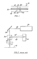
- Figure 1 is a partial cross section of an optical information recording disc depicting an inclusion- type defect therein.
- Figure 2 is a schematic diagram of a prior art laser beam defect detecting apparatus.
- Figure 3 is a schematic diagram of a laser beam defect detecting apparatus according to the principles of the present invention.
- Figure 4 is a lens diagram showing the incident light beam of the present invention.
- Figure 5 is a lens diagram depicting the incident and reflected light beam of the present invention off of a defect.
- Figure 6 is a schematic diagram depicting the reflected light beam from the scanned surface along two different paths.
- Figure 7 is a schematic diagram of a light beam detector used in the present invention.
- Figure 1 is a cross sectional diagram of a portion of an
optical disc 10 which shows an "inclusion" type defect. Thedisc 10 is made of two clearplastic disc parts 12 and 14 which are bonded together with a layer of adhesive 16. Each of the disc'sparts 12, 14, is provided with a layer ofreflective material 18, 20 as shown. The information tracks described above are formed in theselayers 18, 20 in a completed disc according to one of several different known processes. - A small particle of contaminating material 22 is present in the
adhesive layer 16 between theparts 12, 14. Such a particle can be introduced in the manufacturing process in a number of ways, for example, if a dust particle lands on the adhesive prior to the bonding together of the disc parts. The presence of the particle 22 results in an inclusion which causes bulgingareas reflective layers 18, 20. If the slope of the sides of such a bulge is great enough the focused servo system cannot maintain focus in the vicinity of the bulge and the aforementioned problems arise. Other kinds of defects causing similar sloped surfaces in thereflective layers 18, 20 may also be present in thedisc 10. - One prior art arrangement which was devised in order to detect the presence of such defects is depicted in Figure 2. A
laser 30 provides a polarized laserlight beam output 32 which is directed to amirror 34 where it is reflected to pass through apolarizing beam splitter 36. The light beam then passes through aquarter wavelength plate 38 before being reflected off of thesurface 18, which is made to move laterally with respect to thebeam 32. Theincident beam 32 is directed perpendicularly with respect to the plane of thesurface 18. Therefore, if thesurface 18 contains no irregularities, the reflectedbeam 42 will be directed back along the same path to thepolarizing beam splitter 36 after passing again through thequarter wavelength plate 38. After thus passing twice through thequarter wavelength plate 38, thelight beam 42 is rotated 90° with respect to theincident light beam 32. Therefore, substantially all of the reflectedlight beam 42 will be reflected by thebeam splitter 36 as shown. - As described above in connection with Figure 1, the sides of the defect present a reflective surface which is oriented at an angle with respect to the plane of the
reflective surface 18. Consequently, when theincident beam 32 of the apparatus of Figure 2 encounters such a defect it is not reflected back along the same path, but rather it is reflected at some angle with respect to the incident path. Such a beam 42' is reflected off of thebeam splitter 36 in a different direction. A position-sensitive photo detector 44 is placed along the path of the light beams 42, 42' reflected off of thebeam splitter 36 and a signal is derived which is representative of the displacement x of the reflected beam 42'. Since the distance of x shown in Figure 3 corresponds geometrically to the angle D of the reflected beam 42' with respect to the reflectedbeam 32 the output signal of the photodetector provides a measure of the presence of a defect. - Such an arrangement has proven effective in detecting defects in optical discs.
- However, such an apparatus is not readily adaptable to provide a spot of light for defect detection close enough to the "read" laser spot or "write" laser spot in a reading or recording apparatus for desired accuracy of detection of defect location and size with respect to the primary (reading or writing) laser spot. For example, it is desired to place the defect detecting laser spot approximately 0.1 to 0.2 mm from the primary laser spot in the case of a video playback device in order to obtain the highest possible accuracy of detection of the location of defects with respect to the primary laser beam spot while at the same time providing sufficient lead of the defect detecting spot on the disc in advance of the primary laser beam spot to permit automatic switching without overshoot from a fast scan mode to a play mode within the response time of the player.
- However, the objective lens and objective lens motion assembly used in the focus servo system are relatively large and must be placed close to the disc; a typical objective lens is about 8 mm in diameter and typically rides approximately 3 mm above the surface of the disc. The objective lens motion assembly surrounds the lens, further extending the diameter of the arrangement. These elements thus present a problem in adapting the arrangement of Figure 2 to an optical recorder playback apparatus so as to provide defect detection with desired closeness to the primary laser beam spot.
- Figure 3 of the drawings shows in block diagram form the preferred embodiment of the present invention. In accordance with this embodiment of the invention a standard video disc player apparatus has been modified to include the off-axis light beam defect detector of the present invention. A first
laser beam source 50 is provided which emits a polarized beam ofcoherent light 52. This beam oflight 52 is reflected off ofmirrors 54 and 56 through a defraction grating 58 andbeam diverting lens 60 to a polarization beam splitter 62. The polarization of thelight beam 52 is oriented so that a substantial portion of the beam passes through the beam splitter. Thelaser light 52 which passes through the beam splitter 62 is directed through aquarter wavelength plate 64 to afurther mirror 66 where it is directed to anobjective lens 68. Theobjective lens 68 focuses the diverging beam oflaser light 52 to a spot 70 on the surface of avideo disc 10. Thevideo disc 10 is clamped to aspindle 74 which is rotated at high speeds by aspindle drive system 75 so that, in conjunction with a linear tracking mechanism associated with the objective lens (not shown) a spiral tracking function may be effected for the spot 70 of laser light on the disc 72, as is well known in the art. The light 52 is reflected back from the disc through theobjective lens 68 where it is reflected off ofmirror 66 and directed back throughquarter wavelength plate 64 to thepolarizing beam splitter 52. Because the reflected light directed to the beam splitter 62 passes through thequarter wavelength plate 64 twice the direction of polarization is rotated by 90° with respect to theincident light 52. Therefore, a substantial portion of the reflected light will be reflected by the beam splitter 62 at right angles to the central axis of the incident light beam due to the orientation of the surface of the beam splitter 62 as shown. - A focusing
lens 76 is placed in the path of the light which has been reflected by the beam splitter 62 to focus that light onto aphotodetector 78. Thephotodetector 78 may be arranged so as to provide an output signal representative of the state of focus of the spot 70 of light with respect to thevideo disc 10. Such output signal may be provided on asignal line 80 to a servo control mechanism 82 which, in response to the signal online 80 maintains a relative spacing between theobjective lens 68 and thedisc 10 so as to maintain the spot of light 70 in focus on the reflective surface of thedisc 10. - The construction and operation of the foregoing portion of the present invention are well known in the art.
- In accordance with the-principles of the present invention, a second laser
light beam source 84 is provided which emits a second, auxiliary polarizedlaser light beam 86. Thissecond beam 86 passes through an auxiliary light beam focusing lens 88 tomirrors 90 and 92 which direct the auxiliarylaser light beam 86 through the polarizing beam splitter 62 so as to pass through thequarter wavelength plate 64. This beam then passes to themirror 66 which directs thebeam 86 through theobjective lens 68 which focuses thebeam 86 to asecond spot 94 on the surface of thevideo disc 10. The light from theauxiliary beam 86 reflected off of thevideo disc 10 passes back through theobjective lens 68 and is reflected bymirror 66 through thequarter wavelength plate 64 to the polarizing beam splitter 62. Because it passes twice through thequarter wavelength plate 64, a substantial portion of this light 96 is reflected by the beam splitter 62. A mirror 98 is placed in the path of the reflected light beam 96 which directs the light beam 96 to aphotodetector subsystem 100. - The operation of the embodiment of the present invention just disclosed will now be described.
- Referring now to Figure 4, a simplified diagram is shown of the
objective lens 68 and thevideo disc 10. As can be seen, the incident auxiliary beam oflaser light 52 converges due to the focusing action of the auxiliary beam focusing lens 88 (Fig. 3) to afocal point 102 which, by appropriate selection and arrangement of the focusing lens 88, using well-known techniques, is made to coincide with the focal point f of theobjective lens 68 on the opposite side of thelens 68 from thevideo disc 10. This causes thelight beam 52 which emerges from theobjective lens 68 to be a collimated beam of light parallel with the central axis of the lens. By thus orienting the disc and collimating thelight beam 52 which is incident on thedisc 10, the size and location of the spot formed by thebeam 52 on thedisc 10 remain constant despite any variation in the spacing between theobjective lens 68 and thedisc 10 which might occur. - If the reflective surface of the
video disc 10 is completely flat, theincident light beam 52 will be reflected off of thedisc 10 and be directed back along the same path as the incident beam. Thus, in Figure 5 thelight beam 52 represents both the incident and the reflected light beam from a completely flat surface. - Referring now to Figure 5, a simplified diagram of the
objective lens 68 and the surface of thevideo disc 10 is shown in connection with the presence of adefect 110 shown greatly enlarged as to scale for the purposes of clarity of description. Also for purposes of clarity, light beams are depicted as single lines. - As shown, the
light beam 52 is incident on the sloping side surface of thedefect 110. The tangent of the surface of thedefect 110, is depicted byline 112 which makes an angle r with respect to the flat surface of thedisc 10. The reflectedbeam 114 forms an angle of 2r with respect to theincident light beam 52. Thus the lateral deflection "r" of the light beam at the pupil plane of theobjective lens 6 is given by:
objective lens 68 from the surface of the video disc 62. A representative value of s for a conventional video disc player is approximately 8.2 mm. For such a configuration,
- Figure 6 is a schematic diagram showing the relationship between the
objective lens 68, the surface of thevideo disc 10, and thephotodetector subsystem 100. The beam ofreflective light 114 is shown deflected by the distance r at theobjective lens 68, as described above in connection with Figure 5. The path of the reflectedlight beam 114 in the case where no defect is present and reflection is normal to the reflective surface of thedisc 10 is also shown for reference. - As can be seen, the reflected
beam point 116 located at theback image plate 118 of theobjective lens 68. The beams then diverge and impinge on thephotodetector subsystem 100, as shown. Thephotodetector subsystem 100 is located adistance 1 from theback image plane 118, as shown byarrow 120. Thisdistance 1 is equal to the long conjugate of theobjective lens 68. Because thephotodetector subsystem 100 is located at this distance from theback image plane 118, it is in a 1:1 conjugate relationship with the lens and, consequently, any lateral deflection r at theobjective lens 68 due to deflection of the reflectedlight beam 114 will give rise to a corresponding lateral deflection r of theincident light beam 114 on thephotodetector subsystem 100, as shown. - Figure 7 is a schematic diagram of the
photodetector subsystem 100 shown in Figure 3. A split (bi-cell)photodetector 100 is provided, having a left cell A and a right cell B. Thisphotodetector 100 may be a quadrature photodetector having each of the left and right quadrant cells connected together electrically to provide a split cell function. This permits measurement of the lateral deviation of the light beam incident on thephotodetector 100 in one direction. In the preferred embodiment, lateral deflections of thelight beam 114 corresponding to defect slopes in the tangential direction are detected, while defect slopes in the radial direction are not detected. It has been found that motions induced in one or more of the optical elements of the video disc player, for example, mirror 66 (Fig. 3) by the action of the radial tracking error servo system give rise to motions of the incidentauxiliary laser beam 86. These motions of thebeam 86 result in lateral motions of the light beam spot on the photodetector 122 (Fig. 7) which cause false defect signals in the radial direction. Accordingly, the preferred embodiment of the present invention only detects defects in the tangential direction. It should be understood, however, that in the absence of such induced beam motion errors in the radial direction, defect detection may be effected in the radial direction by the appropriate arrangement of a split detector or by the provision of a quadrant photodetector. - Returning now to Figure 7, the
circular boundary 124 of a spot of light incident on thephoto cell 100 is shown, off-set by the distance r from the line of separation between Cell A and Cell B. It will be recalled that the distance r represents the lateral deviation of the reflected beam of light at the pupil plane of theobjective lens 68, described above in connection with Figure 5. It will also be appreciated that small spots of light do not have well defined boundaries due to defraction and other effects. Following convention, it will be assumed that thecircular boundary 124 represents the 1/ez light intensity boundary of a spot of light. - The presence of light on cells A and B give rise to currents IA, IB on
output signal lines Signal lines differential amplifier 130 which produces an output onsignal line 132 proportional the difference between signals IA and IB. It will be appreciated that when thecenter 134 of the incident beam coincides with the boundary 136 between the cell A and cell B of the photodetector 122 currents IA and IB are equal and thedifferential amplifier 120 produces no output. However, if the beam is deflected, for example, to the right as shown in Figure 7, one cell receives proportionately more light than the other. This is represented in the figure by the cross hatchedarea 138 in the Figure. - The output on
line 132 from thedifferential amplifier 130 is proportional to twice the amount of light falling on the cross hatchedarea 138. Therefore, knowing the distribution of light within theboundary 124 of the spot, the performance characteristics of the photodetector 122, and the electrical characteristics of thedifferential amplifier 130, a quantitative measurement of the dimension r may be made based on the magnitude of the output signal online 132. If the size of the spot 94 (Fig. 3) on thevideo disc 10 is small with respect to the dimension of the detected defect, then r may be computed as well using the formula r = 28s, explained above. Thus, a very accurate measurement of the size of a defect can be made. These calculations are well within the scope of one skilled in this art. - Returning now to Figure 3, it can be seen that by appropriate placement of
mirror 92, with respect to the central axis of the first laser beam,spot 94 may be located on thedisc 10 wherever desired with respect to the spot 70 of the first laser beam, limited by the field of view of theobjective lens 68 and the radial dimensions of thefirst laser beam 52 at the location of the deflectingmirror 92. This radial dimension may be made to be quite small by placing the deflecting mirror 90 close to the focal point of the diverginglens 60 where the radial dimensions of thelaser beam 52 reach a minimum. In the preferred embodiment of the present invention, the placement of the deflectingmirror 92 is adjusted so that the center of the auxiliarylaser beam spot 94 is located at a distance of approximately .1 to .2 mm from the spot 70 of thefirst laser beam 52 radially in the direction of forward reading of thefirst laser beam 52. Thus, if the apparatus reads by advancing the laser beam spot 70 outwardly in a spiralling fashion, the center of thespot 94 is spaced approximately .15 mm from the center of spot 70 in the radial direction and toward the outside of the disc. - In addition, the ratio of the focal lengths of the auxiliary beam converging lens 88 to the
objective lens 68 in the preferred embodiment of the present invention is selected, according to well-known principles, to produce aspot 94 having a diameter of approximately 80 microns. It has been found that the combination of a spot diameter of 80 microns and a radial spacing of approximately .15 mm between thespots 70 and 94, as described above, permits thevideo disc 10 to be read rapidly in a "fast scan mode" and, upon the detection of a defect, the video disc player can automatically switched to a "read mode" without the necessity of backing' up the objective lens. The previously detected defect area may then simply be read by the first laser spot 70 and the video picture viewed to determine if the defect gives rise to acceptable disruptions in the video picture. - It will be appreciated from the foregoing that the present invention represents a significant advance in the field of defect detection in optical discs. In particular, the invention provides an effective apparatus for providing an accurate measurement of size and location of defects in the reflective surface of optical discs with respect to a reading or writing laser beam spot on the disc. This permits much less time consuming quality control in video optical disc manufacture and also permits defective optical discs to be used as computer data storage elements through the accurate placement of appropriate codes in affected information tracks as defects are detected in the disc and the data is "written" therein. In addition, the apparatus is readily adaptable to existing laser beam reading or writing apparatus with a minimum of modification.
- Although the invention has been described in detail with respect to its presently preferred embodiment, it would be understood by one of ordinary skill in the art that various modifications can be made without departing from the spirit of the scope of the invention. Accordingly, it is not intended that the invention be limited except as by the appended claims.
Claims (4)
Priority Applications (1)
| Application Number | Priority Date | Filing Date | Title |
|---|---|---|---|
| AT82108229T ATE19311T1 (en) | 1981-09-08 | 1982-09-07 | DEFECT DETECTION DEVICE USING AN OFF-CENTER BEAM. |
Applications Claiming Priority (2)
| Application Number | Priority Date | Filing Date | Title |
|---|---|---|---|
| US06/300,364 US4412743A (en) | 1981-09-08 | 1981-09-08 | Off-axis light beam defect detector |
| US300364 | 1981-09-08 |
Publications (2)
| Publication Number | Publication Date |
|---|---|
| EP0074115A1 EP0074115A1 (en) | 1983-03-16 |
| EP0074115B1 true EP0074115B1 (en) | 1986-04-16 |
Family
ID=23158782
Family Applications (1)
| Application Number | Title | Priority Date | Filing Date |
|---|---|---|---|
| EP82108229A Expired EP0074115B1 (en) | 1981-09-08 | 1982-09-07 | Off-axis light beam defect detector |
Country Status (8)
| Country | Link |
|---|---|
| US (1) | US4412743A (en) |
| EP (1) | EP0074115B1 (en) |
| JP (1) | JPS58105443A (en) |
| KR (1) | KR890002318B1 (en) |
| AT (1) | ATE19311T1 (en) |
| DE (1) | DE3270640D1 (en) |
| HK (1) | HK72689A (en) |
| SG (1) | SG19389G (en) |
Families Citing this family (16)
| Publication number | Priority date | Publication date | Assignee | Title |
|---|---|---|---|---|
| JPS57161640A (en) * | 1981-03-31 | 1982-10-05 | Olympus Optical Co Ltd | Inspecting device for surface |
| DE3503858A1 (en) * | 1985-02-05 | 1986-08-21 | Daimler-Benz Ag, 7000 Stuttgart | DEVICE FOR DETERMINING LOW-ORDER DESIGN ERRORS |
| EP0378177B1 (en) * | 1989-01-10 | 1995-08-30 | Canon Kabushiki Kaisha | Image forming apparatus |
| US5504732A (en) * | 1990-08-15 | 1996-04-02 | Del Mar Avionics | Null inflection detection and pulse expand latch in an optical recording system |
| GB9205655D0 (en) * | 1992-03-14 | 1992-04-29 | Roke Manor Research | Improvements in or relating to surface curvature measurement |
| US5389794A (en) * | 1992-11-25 | 1995-02-14 | Qc Optics, Inc. | Surface pit and mound detection and discrimination system and method |
| JPH07209202A (en) * | 1994-01-21 | 1995-08-11 | Canon Inc | Surface state inspection equipment, exposure apparatus employing it, and production of device using the exposure apparatus |
| US5978329A (en) * | 1995-06-07 | 1999-11-02 | Discovision Associates | Technique for closed loop servo operation in optical disc tracking control |
| JPH09180417A (en) * | 1995-11-30 | 1997-07-11 | Daewoo Electron Co Ltd | Flatness inspection device of drive chassis of disk player |
| ES2112224T1 (en) * | 1995-12-06 | 1998-04-01 | Discovision Ass | APPARATUS AND METHOD FOR FOCUS CONTROL. |
| US5689485A (en) * | 1996-04-01 | 1997-11-18 | Discovision Associates | Tracking control apparatus and method |
| US6548821B1 (en) | 1999-06-21 | 2003-04-15 | Komag, Inc. | Method and apparatus for inspecting substrates |
| US6566674B1 (en) | 1999-06-21 | 2003-05-20 | Komag, Inc. | Method and apparatus for inspecting substrates |
| JP3460678B2 (en) * | 2000-06-02 | 2003-10-27 | 松下電器産業株式会社 | Laser processing method and processing apparatus |
| JP2007193852A (en) * | 2004-03-30 | 2007-08-02 | Pioneer Electronic Corp | Hologram recording medium |
| CN117419646B (en) * | 2023-12-19 | 2024-03-15 | 南京牧镭激光科技股份有限公司 | Method and system for monitoring displacement of fan spindle based on laser sensor |
Family Cites Families (9)
| Publication number | Priority date | Publication date | Assignee | Title |
|---|---|---|---|---|
| JPS5855567B2 (en) * | 1975-06-06 | 1983-12-10 | 株式会社日立製作所 | The best way to do it |
| NL182990C (en) * | 1975-07-07 | 1988-06-16 | Philips Nv | DEVICE FOR READING A RADIATION-REFLECTING RECORD CARRIER. |
| US4030835A (en) * | 1976-05-28 | 1977-06-21 | Rca Corporation | Defect detection system |
| JPS5439103A (en) * | 1977-09-02 | 1979-03-26 | Victor Co Of Japan Ltd | Medium locator for fucus servo |
| NL7802860A (en) * | 1978-03-16 | 1979-09-18 | Philips Nv | REGISTRATION CARRIER BODY AND REGISTRATION CARRIER FOR OPTICAL INFORMATION AND DEVICE FOR REGISTRATION AND READ OUT. |
| US4332022A (en) * | 1978-03-27 | 1982-05-25 | Discovision Associates | Tracking system and method for video disc player |
| JPS5625240A (en) * | 1979-06-04 | 1981-03-11 | Discovision Ass | Method and device for recording data signal on recording medium |
| FR2483664B1 (en) * | 1980-05-28 | 1985-06-28 | Thomson Csf | OPTICAL RECORDING-READING DEVICE ON AN INFORMATION MEDIUM AND OPTICAL MEMORY SYSTEM COMPRISING SUCH A DEVICE |
| US4357533A (en) * | 1980-07-14 | 1982-11-02 | Discovision Associates | Focus detector for an optical disc playback system |
-
1981
- 1981-09-08 US US06/300,364 patent/US4412743A/en not_active Expired - Lifetime
-
1982
- 1982-09-07 JP JP57154736A patent/JPS58105443A/en active Pending
- 1982-09-07 KR KR8204048A patent/KR890002318B1/en active
- 1982-09-07 AT AT82108229T patent/ATE19311T1/en not_active IP Right Cessation
- 1982-09-07 DE DE8282108229T patent/DE3270640D1/en not_active Expired
- 1982-09-07 EP EP82108229A patent/EP0074115B1/en not_active Expired
-
1989
- 1989-03-31 SG SG193/89A patent/SG19389G/en unknown
- 1989-09-07 HK HK726/89A patent/HK72689A/en not_active IP Right Cessation
Also Published As
| Publication number | Publication date |
|---|---|
| EP0074115A1 (en) | 1983-03-16 |
| ATE19311T1 (en) | 1986-05-15 |
| KR890002318B1 (en) | 1989-06-30 |
| HK72689A (en) | 1989-09-14 |
| US4412743A (en) | 1983-11-01 |
| KR840001719A (en) | 1984-05-16 |
| SG19389G (en) | 1989-09-29 |
| JPS58105443A (en) | 1983-06-23 |
| DE3270640D1 (en) | 1986-05-22 |
Similar Documents
| Publication | Publication Date | Title |
|---|---|---|
| EP0074115B1 (en) | Off-axis light beam defect detector | |
| US4100577A (en) | Apparatus for optically reading signal information recorded on a reflective record medium surface | |
| EP0414380B1 (en) | Optical recording and reproducing apparatus and adaptor for use with said apparatus | |
| US4821251A (en) | Method and apparatus for recording or reproducing information in or from only a sector of an optical disk track without any defect by shifting a light beam to an adjacent track before a defective sector | |
| EP0081786A2 (en) | Storage medium track pitch detector | |
| KR19980702367A (en) | Optical data recording / reproducing medium and recording method | |
| US4759007A (en) | Storage medium track pitch detector | |
| US4525825A (en) | Method and apparatus for detecting focussing and tracking error signals | |
| US5105411A (en) | Apparatus for detecting and correcting focusing and tracking errors | |
| EP0523334B1 (en) | Optical information recording medium and reproducing apparatus for reproducing information from the medium | |
| US4566090A (en) | Storage medium track pitch detector | |
| KR100689722B1 (en) | Optical scanning unit comprising a detection system for detecting the position of a movable element within the unit | |
| US5953304A (en) | Optical disc recording or playback device with corrected focus optical scanning | |
| JP3260771B2 (en) | Optical focus detection apparatus and method for detecting focus of light beam | |
| KR19990006653A (en) | Apparatus for optically recording data in the disc | |
| US5606542A (en) | Optical pickup using three beam tracking method | |
| US4648084A (en) | Storage medium track pitch detector | |
| JPS61220147A (en) | Optical head | |
| JP3373747B2 (en) | Disk tilt detector | |
| JP2660523B2 (en) | Optical recording / reproducing device | |
| JPS62239344A (en) | Optical information recording medium | |
| US5532477A (en) | Optical pickup apparatus having lens group for determining paths of an incident beam and a reflected & beam | |
| JP2687928B2 (en) | Optical disk media | |
| JPH04366428A (en) | Optical head and optical information recording device | |
| JPS62239333A (en) | Tracking signal detecting method |
Legal Events
| Date | Code | Title | Description |
|---|---|---|---|
| PUAI | Public reference made under article 153(3) epc to a published international application that has entered the european phase |
Free format text: ORIGINAL CODE: 0009012 |
|
| AK | Designated contracting states |
Designated state(s): AT BE CH DE FR GB IT LI LU NL SE |
|
| 17P | Request for examination filed |
Effective date: 19830805 |
|
| ITF | It: translation for a ep patent filed |
Owner name: SOCIETA' ITALIANA BREVETTI S.P.A. |
|
| GRAA | (expected) grant |
Free format text: ORIGINAL CODE: 0009210 |
|
| AK | Designated contracting states |
Kind code of ref document: B1 Designated state(s): AT BE CH DE FR GB IT LI LU NL SE |
|
| REF | Corresponds to: |
Ref document number: 19311 Country of ref document: AT Date of ref document: 19860515 Kind code of ref document: T |
|
| REF | Corresponds to: |
Ref document number: 3270640 Country of ref document: DE Date of ref document: 19860522 |
|
| ET | Fr: translation filed | ||
| PG25 | Lapsed in a contracting state [announced via postgrant information from national office to epo] |
Ref country code: LU Free format text: LAPSE BECAUSE OF NON-PAYMENT OF DUE FEES Effective date: 19860930 |
|
| PLBI | Opposition filed |
Free format text: ORIGINAL CODE: 0009260 |
|
| 26 | Opposition filed |
Opponent name: N.V. PHILIPS' GLOEILAMPENFABRIEKEN Effective date: 19870116 |
|
| NLR1 | Nl: opposition has been filed with the epo |
Opponent name: N.V. PHILIPS' GLOEILAMPENFABRIEKEN. |
|
| PGFP | Annual fee paid to national office [announced via postgrant information from national office to epo] |
Ref country code: NL Payment date: 19870930 Year of fee payment: 6 |
|
| PLBM | Termination of opposition procedure: date of legal effect published |
Free format text: ORIGINAL CODE: 0009276 |
|
| STAA | Information on the status of an ep patent application or granted ep patent |
Free format text: STATUS: OPPOSITION PROCEDURE CLOSED |
|
| 27C | Opposition proceedings terminated |
Effective date: 19880418 |
|
| PG25 | Lapsed in a contracting state [announced via postgrant information from national office to epo] |
Ref country code: BE Effective date: 19880930 |
|
| BERE | Be: lapsed |
Owner name: DISCOVISION ASSOCIATES Effective date: 19880930 |
|
| PG25 | Lapsed in a contracting state [announced via postgrant information from national office to epo] |
Ref country code: NL Effective date: 19890401 |
|
| NLV4 | Nl: lapsed or anulled due to non-payment of the annual fee | ||
| ITTA | It: last paid annual fee | ||
| EAL | Se: european patent in force in sweden |
Ref document number: 82108229.4 |
|
| PGFP | Annual fee paid to national office [announced via postgrant information from national office to epo] |
Ref country code: FR Payment date: 20010817 Year of fee payment: 20 |
|
| PGFP | Annual fee paid to national office [announced via postgrant information from national office to epo] |
Ref country code: SE Payment date: 20010820 Year of fee payment: 20 Ref country code: DE Payment date: 20010820 Year of fee payment: 20 Ref country code: CH Payment date: 20010820 Year of fee payment: 20 |
|
| PGFP | Annual fee paid to national office [announced via postgrant information from national office to epo] |
Ref country code: GB Payment date: 20010821 Year of fee payment: 20 Ref country code: AT Payment date: 20010821 Year of fee payment: 20 |
|
| REG | Reference to a national code |
Ref country code: GB Ref legal event code: IF02 |
|
| PG25 | Lapsed in a contracting state [announced via postgrant information from national office to epo] |
Ref country code: LI Free format text: LAPSE BECAUSE OF EXPIRATION OF PROTECTION Effective date: 20020906 Ref country code: GB Free format text: LAPSE BECAUSE OF EXPIRATION OF PROTECTION Effective date: 20020906 Ref country code: CH Free format text: LAPSE BECAUSE OF EXPIRATION OF PROTECTION Effective date: 20020906 |
|
| PG25 | Lapsed in a contracting state [announced via postgrant information from national office to epo] |
Ref country code: AT Free format text: LAPSE BECAUSE OF EXPIRATION OF PROTECTION Effective date: 20020907 |
|
| REG | Reference to a national code |
Ref country code: CH Ref legal event code: PL |
|
| REG | Reference to a national code |
Ref country code: GB Ref legal event code: PE20 Effective date: 20020906 |
|
| EUG | Se: european patent has lapsed |
Ref document number: 82108229.4 |