EP0073166B1 - Hinged back door of an automotive vehicle - Google Patents
Hinged back door of an automotive vehicle Download PDFInfo
- Publication number
- EP0073166B1 EP0073166B1 EP82401535A EP82401535A EP0073166B1 EP 0073166 B1 EP0073166 B1 EP 0073166B1 EP 82401535 A EP82401535 A EP 82401535A EP 82401535 A EP82401535 A EP 82401535A EP 0073166 B1 EP0073166 B1 EP 0073166B1
- Authority
- EP
- European Patent Office
- Prior art keywords
- door
- door glass
- spacer
- hole
- glass
- Prior art date
- Legal status (The legal status is an assumption and is not a legal conclusion. Google has not performed a legal analysis and makes no representation as to the accuracy of the status listed.)
- Expired
Links
- 239000011521 glass Substances 0.000 claims description 53
- 125000006850 spacer group Chemical group 0.000 claims description 31
- 238000012856 packing Methods 0.000 claims description 18
- 230000004323 axial length Effects 0.000 description 4
- XLYOFNOQVPJJNP-UHFFFAOYSA-N water Substances O XLYOFNOQVPJJNP-UHFFFAOYSA-N 0.000 description 2
- 239000000463 material Substances 0.000 description 1
- 239000002184 metal Substances 0.000 description 1
- 230000003287 optical effect Effects 0.000 description 1
- 239000012858 resilient material Substances 0.000 description 1
- 229920003002 synthetic resin Polymers 0.000 description 1
- 239000000057 synthetic resin Substances 0.000 description 1
Images
Classifications
-
- E—FIXED CONSTRUCTIONS
- E05—LOCKS; KEYS; WINDOW OR DOOR FITTINGS; SAFES
- E05D—HINGES OR SUSPENSION DEVICES FOR DOORS, WINDOWS OR WINGS
- E05D5/00—Construction of single parts, e.g. the parts for attachment
- E05D5/02—Parts for attachment, e.g. flaps
- E05D5/0246—Parts for attachment, e.g. flaps for attachment to glass panels
-
- E—FIXED CONSTRUCTIONS
- E05—LOCKS; KEYS; WINDOW OR DOOR FITTINGS; SAFES
- E05Y—INDEXING SCHEME ASSOCIATED WITH SUBCLASSES E05D AND E05F, RELATING TO CONSTRUCTION ELEMENTS, ELECTRIC CONTROL, POWER SUPPLY, POWER SIGNAL OR TRANSMISSION, USER INTERFACES, MOUNTING OR COUPLING, DETAILS, ACCESSORIES, AUXILIARY OPERATIONS NOT OTHERWISE PROVIDED FOR, APPLICATION THEREOF
- E05Y2900/00—Application of doors, windows, wings or fittings thereof
- E05Y2900/50—Application of doors, windows, wings or fittings thereof for vehicles
Definitions
- This invention relates to a glazed back-door hinged to the body of a station wagon or coupe- type automotive vehicle.
- Some of the prior art automotive vehicles such as station wagons or coupes, have back doors made of window glazing, which are pivotally mounted on the vehicle bodies by hinges.
- One type of these hinges has a movable member and a backing member, which clamp therebetween part of the glass of the door with backings interposed between the glass and both members to protect the door glazing.
- the distance between the members can be changed by screws to adjust the clamping force on the glass.
- French patents N° 1 491 438 and 2 215 827 both reveal hinge for a glass door comprising first and second deformable packing sheets provided between the glass door and movable and backing members, respectively, and a plastic spacer provided between the movable member and the backing member.
- the spacer has an axial length which substantially corresponds to the thickness of the glass door and screws are also provided for connecting the backing member of the hinge to the movable member.
- a hinged back door of an automotive vehicle comprises:
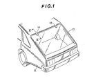
- FIG. 1 there is shown the rear of an automotive vehicle, which has a glazed back-door 10 pivotally mounted on the rear edge of the roof panel of a vehicle body 12 by means of a pair of hinges 14 of this invention.
- the two hinges 14 are identical.
- the hinge 14 has a stationary first member 16, a movable second member 18, and a backing member 20.
- One edge of the movable member 18 is pivoted at 22 to one end of the stationary member 16.
- the other end of the stationary member 16 is bolted to the vehicle body roof panel 12.
- the movable member 18 is thus free to rotate about the pivot 22.
- the movable and backing members 18 and 20 essentially consist of substantially flat plates.
- the backing plate 20 is connected in parallel with the movable plate 18 by means of a plurality of screws 24.
- the back door 10 essentially consists of a sheet of window glazing or glass, and is clamped securely between the movable and backing plates 18 and 20 in a parallel manner to be hinged virtually to the roof panel 12.
- the door glass 10 is free to pivot in conjunction with the movable plate 18 of the hinge 14.
- the rearward edges of the movable and backing plates 18 and 20 are aligned.
- the backing plate 20 is shorter in total longitudinal length than the movable plate 18, so that the plate 18 extends frontward beyond the plate 20.
- the plates 18 and 20 are outside and inside the vehicle respectively.
- the door glass 10 extends frontward beyond the plate 20 but not as far as plate 18.
- a weatherstrip 26 is provided between the rear edge of the roof panel 12 and the front edge of the door glass 10 to prevent ingress of rain water into the interior of the vehicle without hampering movement of the door 10.
- sheets of deformable or resilient packings are provided between the door glass 10 and the plate 18, and between the door glass 10 and the plate 20, respectively, to prevent ingress of rain water into the interior of the vehicle and protect the door glass 10.
- the movable plate 18 has a plurality of bosses 32 of circular cross-section, which protrude perpendicularly from the rest of the plate 18 toward the plate 20.
- the movable plate 18 also has a plurality of threaded holes 34, which are coaxial with the bosses 32 respectively and open at the distal ends of the bosses 32 respectively.
- the backing plate 20 has therethrough a plurality of non-threaded holes 36 aligned with the respective holes 34.
- the door glass 10 has therethrough a plurality of holes 38 of circular cross-section aligned with the respective holes 34 and 36.
- the packings 28 and 30 respectively have therethrough a plurality of circular openings 42 and 44 substantially aligned with the respective holes 38 and of inside diameters greater than the holes 38.
- the holes 38 through the door glass 10 have an inside diameter considerably greater than the outside diameters of the respective bosses 32 so as to accommodate therein the respective bosses 32.
- the screws 24 coaxially extend through or in the respective holes 34,36,38,42 and 44 in such a manner that the distal ends of the screws 24 anchor in the respective holes 34 and the heads thereof seat in the respective holes 36.
- the screws 24 engage the movable plate 18 by means of the threads.
- the holes 36 are recessed at the ends remote from the plate 18 so as to accommodate the heads of the screws 24, so that the screws 24 can rotatably engage the backing plate 20. As the screws 24 are turned, the gap or the distance between the movable and backing plates 18 and 20 is varied.
- a plurality of the ring spacers 46 are provided between the plates 18 and 20, and extend coaxially through the respective holes 38 and openings 42 and 44.
- the spacers 46 have an outside diameter substantially equal to the inside diameter of the holes 38, and therefore snugly fit within the respective holes 38.
- the spacers 46 accommodate the respective screws 24 and the bosses 32.
- the inside diameters of the spacers 46 are considerably greater than the outside diameters of the screws 24 and the bosses 32, so that the spacers 46 do not contact the screws 24 or the bosses 32.
- each of the spacers 46 consists of a hollow cylindrical core 48 and a layer 50 fixed concentrically onto the periphery of the core 48.
- the core 48 is made of a rigid material, such as metal or synthetic resin.
- the layer 50 is made of deformable or resilient material, such as rubber fixed to the core 48 by normal adhesion or heat-utilizing adhesion. The layer 50 prevents direct contact between the door glass 10 and the core 48 so as to protect the door glass 10.
- Each of the spacers 46 has an axial length greater than the thickness of the door glass 10 but smaller than the sum of the thickness of the door glass 10 and the original or relaxed thicknesses of the packings 28 and 30 so as to define the minimum gap or distance between the plates 18 and 20.
- the axial length of each spacer 46 is chosen so that when the screws 24 are tightened until the plates 18 and 20 come into contact with the spacers 46, the plates 18 and 20 will clamp therebetween the door glass 10 by way of the packings 28 and 30 with an optimal magnitude of force exerted on the door glass 10.
- the optimal magnitude of clamping force is defined as that which ensures the most reliable clamping of the glass plate 10 without damaging it.
- each boss 32 has an axial length smaller than that of the respective spacers 46 so as to not come into contact with the backing plate 20.
Landscapes
- Engineering & Computer Science (AREA)
- Mechanical Engineering (AREA)
- Window Of Vehicle (AREA)
- Hinges (AREA)
- Body Structure For Vehicles (AREA)
Description
- This invention relates to a glazed back-door hinged to the body of a station wagon or coupe- type automotive vehicle.
- Some of the prior art automotive vehicles, such as station wagons or coupes, have back doors made of window glazing, which are pivotally mounted on the vehicle bodies by hinges. One type of these hinges has a movable member and a backing member, which clamp therebetween part of the glass of the door with backings interposed between the glass and both members to protect the door glazing. The distance between the members can be changed by screws to adjust the clamping force on the glass. However, it is usually difficult to easily adjust the clamping force to an optimal level which ensures reliable clamping of the glass of the door without damaging it.
- French patents N° 1 491 438 and 2 215 827 both reveal hinge for a glass door comprising first and second deformable packing sheets provided between the glass door and movable and backing members, respectively, and a plastic spacer provided between the movable member and the backing member. The spacer has an axial length which substantially corresponds to the thickness of the glass door and screws are also provided for connecting the backing member of the hinge to the movable member.
- Meanwhile, such a known hinge has for inconvenience that when the screws are too tightened, the two deformable packing sheets are crushed which, in course of time, lead to packing sheets having no longer elasticity necessary for clamping the glass door. This obviously leads to packing sheets no longer ensuring the necessary clamping force of the glass between the movable and backing members.
- Moreover, if the glass door is to be dismounted and remounted, it would be necessary to again tighten the screws more with the risk of damaging the glass of the door with the movable and backing member crushing therebetween part of the glass door.
- It is an object of this invention to provide a hinged back door of an automotive vehicle which can easily set the clamping force on the door glass to an optimal level without damaging said door glass during tightening of the screws, while preventing unwanted translation of the door glass.
- In accordance with this invention, a hinged back door of an automotive vehicle comprises:
- a) a door glass having a through hole;
- b) a spacer positioned through the hole of the door glass and having a through hole;
- c) first and second deformable packings sandwiching the door glass therebetween, each of the two packings having a through hole in alignment with the hole of the door glass, the hole of each of the packings accommodating the spacer;
- d) a movable hinge member and a backing member between which the door glass, the first and second packings, and the spacer are positioned;
- e) a screw extending through the hole of the spacer and engaging both of the movable hinge member and the backing member for forcing the door glass to be clamped between the movable hinge member and the backing member by way of the first and second packings; and
- f) a stationary hinge member to which the movable hinge member is pivotally connected, the stationary hinge member being fixed to the vehicle body; and is characterized in that:
- g) the spacer comprises a rigid member and a resilient member fixed to a periphery of the rigid member, the resilient member contacting the door glass;
- h) the spacer is thicker than the door glass; and
- i) the door glass receives a predetermined clamping force.
- Claims 2 and 3 define preferred embodiments of the invention.
- The present invention will be apparent from the following description of a preferred embodiment thereof, taken in conjunction with the drawings, wherein:
- Figure 1 is a perspective view of the rear of an automotive vehicle having a glazed back-door which is pivoted to the vehicle body by means of hinges of this invention;
- Figure 2 is a cross-sectional view of the hinge of Figure 1 taken along line II-II of Figure 1;
- Figure 3 is an enlarged view of an essential portion of the hinge in Figure 2; and
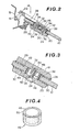
- Figure 4 is a perspective view of the spacer of Figures 2 and 3.
- With reference to Figure 1, there is shown the rear of an automotive vehicle, which has a glazed back-
door 10 pivotally mounted on the rear edge of the roof panel of avehicle body 12 by means of a pair ofhinges 14 of this invention. The twohinges 14 are identical. - As shown in Figure 2, the
hinge 14 has a stationaryfirst member 16, a movablesecond member 18, and abacking member 20. One edge of themovable member 18 is pivoted at 22 to one end of thestationary member 16. The other end of thestationary member 16 is bolted to the vehiclebody roof panel 12. Themovable member 18 is thus free to rotate about thepivot 22. The movable and backingmembers backing plate 20 is connected in parallel with themovable plate 18 by means of a plurality ofscrews 24. - The
back door 10 essentially consists of a sheet of window glazing or glass, and is clamped securely between the movable andbacking plates roof panel 12. Thus, thedoor glass 10 is free to pivot in conjunction with themovable plate 18 of thehinge 14. The rearward edges of the movable andbacking plates backing plate 20 is shorter in total longitudinal length than themovable plate 18, so that theplate 18 extends frontward beyond theplate 20. Theplates door glass 10 extends frontward beyond theplate 20 but not as far asplate 18. Aweatherstrip 26 is provided between the rear edge of theroof panel 12 and the front edge of thedoor glass 10 to prevent ingress of rain water into the interior of the vehicle without hampering movement of thedoor 10. - As shown in Figures 2 and 3, sheets of deformable or resilient packings, for example,
gaskets door glass 10 and theplate 18, and between thedoor glass 10 and theplate 20, respectively, to prevent ingress of rain water into the interior of the vehicle and protect thedoor glass 10. Themovable plate 18 has a plurality ofbosses 32 of circular cross-section, which protrude perpendicularly from the rest of theplate 18 toward theplate 20. Themovable plate 18 also has a plurality of threadedholes 34, which are coaxial with thebosses 32 respectively and open at the distal ends of thebosses 32 respectively. Thebacking plate 20 has therethrough a plurality of non-threadedholes 36 aligned with therespective holes 34. Thedoor glass 10 has therethrough a plurality ofholes 38 of circular cross-section aligned with therespective holes packings circular openings respective holes 38 and of inside diameters greater than theholes 38. Theholes 38 through thedoor glass 10 have an inside diameter considerably greater than the outside diameters of therespective bosses 32 so as to accommodate therein therespective bosses 32. - The
screws 24 coaxially extend through or in therespective holes screws 24 anchor in therespective holes 34 and the heads thereof seat in therespective holes 36. Thescrews 24 engage themovable plate 18 by means of the threads. Theholes 36 are recessed at the ends remote from theplate 18 so as to accommodate the heads of thescrews 24, so that thescrews 24 can rotatably engage thebacking plate 20. As thescrews 24 are turned, the gap or the distance between the movable andbacking plates - A plurality of the
ring spacers 46 are provided between theplates respective holes 38 andopenings spacers 46 have an outside diameter substantially equal to the inside diameter of theholes 38, and therefore snugly fit within therespective holes 38. Thespacers 46 accommodate therespective screws 24 and thebosses 32. The inside diameters of thespacers 46 are considerably greater than the outside diameters of thescrews 24 and thebosses 32, so that thespacers 46 do not contact thescrews 24 or thebosses 32. As best shown in Figures 3 and 4, each of thespacers 46 consists of a hollowcylindrical core 48 and alayer 50 fixed concentrically onto the periphery of thecore 48. Thecore 48 is made of a rigid material, such as metal or synthetic resin. Thelayer 50 is made of deformable or resilient material, such as rubber fixed to thecore 48 by normal adhesion or heat-utilizing adhesion. Thelayer 50 prevents direct contact between thedoor glass 10 and thecore 48 so as to protect thedoor glass 10. - Each of the
spacers 46 has an axial length greater than the thickness of thedoor glass 10 but smaller than the sum of the thickness of thedoor glass 10 and the original or relaxed thicknesses of thepackings plates spacer 46 is chosen so that when thescrews 24 are tightened until theplates spacers 46, theplates door glass 10 by way of thepackings door glass 10. The optimal magnitude of clamping force is defined as that which ensures the most reliable clamping of theglass plate 10 without damaging it. Thus, it is easy to precisely set the clamping force on thedoor glass 10 to an optimal level, since the optical level is obtained by tightening thescrews 24 until theplates spacers 46 and thus thescrews 24 cannot be tightened further. Thespacers 46 prevent excessive force from being exerted on thedoor glass 10. It should be noted that eachboss 32 has an axial length smaller than that of therespective spacers 46 so as to not come into contact with thebacking plate 20. - The considerable difference between the inside diameters of the
spacers 46 and the outside diameters of thebosses 32 compensates for tolerance variations between thedoor glass 10 and thehinges 14, and thus those between thedoor glass 10 and the vehicle body, thereby facilitating assembly and positional adjustments thereof.
Claims (3)
Applications Claiming Priority (2)
| Application Number | Priority Date | Filing Date | Title |
|---|---|---|---|
| JP128325/81 | 1981-08-17 | ||
| JP56128325A JPS5829984A (en) | 1981-08-17 | 1981-08-17 | Hinge joint part structure of opening and closing body made of glass |
Publications (2)
| Publication Number | Publication Date |
|---|---|
| EP0073166A1 EP0073166A1 (en) | 1983-03-02 |
| EP0073166B1 true EP0073166B1 (en) | 1985-11-06 |
Family
ID=14981980
Family Applications (1)
| Application Number | Title | Priority Date | Filing Date |
|---|---|---|---|
| EP82401535A Expired EP0073166B1 (en) | 1981-08-17 | 1982-08-13 | Hinged back door of an automotive vehicle |
Country Status (5)
| Country | Link |
|---|---|
| US (1) | US4535503A (en) |
| EP (1) | EP0073166B1 (en) |
| JP (1) | JPS5829984A (en) |
| AU (1) | AU534299B2 (en) |
| DE (1) | DE3267298D1 (en) |
Cited By (1)
| Publication number | Priority date | Publication date | Assignee | Title |
|---|---|---|---|---|
| DE29500499U1 (en) * | 1995-01-13 | 1995-02-23 | Altura Leiden Holding B.V., Maastricht | Shower partition |
Families Citing this family (16)
| Publication number | Priority date | Publication date | Assignee | Title |
|---|---|---|---|---|
| DE3538064A1 (en) * | 1985-10-25 | 1987-04-30 | Marinoni & Figli Casma | FITTING FOR A WHOLE GLASS WING, ESPECIALLY FOR WHOLE GLASS DOORS, WHOLE GLASS WINDOWS, WHOLE GLASS SHEETS AND WHOLE GLASS DISPLAY WINDOWS |
| DE8701703U1 (en) * | 1987-02-05 | 1987-03-26 | Roloff, Heinz-Rudolf, 4150 Krefeld | Hinge fitting for shower cubicles |
| JPH0826721B2 (en) * | 1989-03-29 | 1996-03-21 | ワイケイケイ株式会社 | Door hinge mounting device |
| JPH03146448A (en) * | 1989-10-31 | 1991-06-21 | Nippon Cement Co Ltd | Production of hydraulic hardened body |
| DE10011188A1 (en) * | 1999-12-17 | 2001-06-28 | Geze Gmbh | Frameless glass wing |
| DE10213131C1 (en) * | 2002-03-23 | 2003-07-31 | Porsche Ag | Hinge for motor vehicle boot lid has studs on lid exterior fitting into holes in hinge arm pivoted to bodywork |
| GB0228028D0 (en) * | 2002-11-30 | 2003-01-08 | Ford Global Tech Inc | An adjustable hinge assembly |
| US7571516B2 (en) * | 2005-08-02 | 2009-08-11 | Simonswerk, Gesellschaft mit beschränkter Haftung | Hinge-plate accommodation element for attaching a hinge plate |
| FR2932418B1 (en) * | 2008-06-12 | 2013-10-11 | Plastic Omnium Cie | OPENING, IN PARTICULAR TAIL, OF VEHICLE |
| US20100199569A1 (en) * | 2009-02-06 | 2010-08-12 | Daniel Piedade | Oversized, stress-transferring spacer for window assembly, and window assembly incorporating the same |
| FR2959472B1 (en) * | 2010-04-29 | 2013-03-08 | Peugeot Citroen Automobiles Sa | REAR PART OF VEHICLE |
| US8966842B2 (en) | 2012-09-17 | 2015-03-03 | Steelcase Inc. | Floor-to-ceiling partition wall assembly |
| EP3029238B1 (en) * | 2014-12-04 | 2021-09-08 | dormakaba Deutschland GmbH | Corner fitting with adjustable clamping area |
| EP3029240A1 (en) * | 2014-12-04 | 2016-06-08 | DORMA Deutschland GmbH | Corner fitting with variably adjustable clamping range |
| US10187007B2 (en) | 2016-04-14 | 2019-01-22 | David C. Hood | Wire cover and mounting bracket |
| US10581375B2 (en) * | 2016-04-14 | 2020-03-03 | David C. Hood | Mounting clip for structure having spaced apart trim |
Family Cites Families (14)
| Publication number | Priority date | Publication date | Assignee | Title |
|---|---|---|---|---|
| CA500650A (en) * | 1954-03-16 | H. Lewis Joseph | Door hinge | |
| US1497217A (en) * | 1922-09-02 | 1924-06-10 | Hodny William La | Mounting for windshield wings |
| US2674487A (en) * | 1950-10-20 | 1954-04-06 | Gen Motors Corp | Closure weather strip |
| US2936050A (en) * | 1953-05-18 | 1960-05-10 | Libbey Owens Ford Glass Co | Hardware attaching means |
| FR1262645A (en) * | 1960-04-20 | 1961-06-05 | Miroiteries De L Ouest | Device allowing the use of glass or tempered glass doors for openings with a height greater than that of the doors |
| FR1491438A (en) * | 1966-06-28 | 1967-08-11 | Saint Gobain | Hinges |
| GB1207957A (en) * | 1966-12-13 | 1970-10-07 | Tonks Birmingham Ltd | Bolt assemblies |
| DE2063015B2 (en) * | 1970-12-22 | 1973-03-08 | FITTING FOR COMPONENTS MADE OF GLASS | |
| FR2215827A5 (en) * | 1973-01-25 | 1974-08-23 | Elmaduc | |
| DE2653559C2 (en) * | 1976-11-25 | 1982-09-02 | Vereinigte Glaswerke Gmbh, 5100 Aachen | Fitting for an all-glass wing or the like. |
| JPS548494U (en) * | 1977-06-20 | 1979-01-20 | ||
| DE2748623C2 (en) * | 1977-10-29 | 1984-04-05 | Vereinigte Glaswerke Gmbh, 5100 Aachen | Hardware for a frameless all-glass door |
| JPS5519803U (en) * | 1978-07-24 | 1980-02-07 | ||
| JPS55160921U (en) * | 1979-05-07 | 1980-11-19 |
-
1981
- 1981-08-17 JP JP56128325A patent/JPS5829984A/en active Pending
-
1982
- 1982-08-06 AU AU86935/82A patent/AU534299B2/en not_active Ceased
- 1982-08-13 EP EP82401535A patent/EP0073166B1/en not_active Expired
- 1982-08-13 DE DE8282401535T patent/DE3267298D1/en not_active Expired
-
1984
- 1984-06-19 US US06/621,887 patent/US4535503A/en not_active Expired - Fee Related
Cited By (1)
| Publication number | Priority date | Publication date | Assignee | Title |
|---|---|---|---|---|
| DE29500499U1 (en) * | 1995-01-13 | 1995-02-23 | Altura Leiden Holding B.V., Maastricht | Shower partition |
Also Published As
| Publication number | Publication date |
|---|---|
| AU8693582A (en) | 1983-02-24 |
| AU534299B2 (en) | 1984-01-19 |
| DE3267298D1 (en) | 1985-12-12 |
| US4535503A (en) | 1985-08-20 |
| EP0073166A1 (en) | 1983-03-02 |
| JPS5829984A (en) | 1983-02-22 |
Similar Documents
| Publication | Publication Date | Title |
|---|---|---|
| EP0073166B1 (en) | Hinged back door of an automotive vehicle | |
| EP0096129B1 (en) | Hinged vehicle window assembly | |
| US4165083A (en) | Arrangements for retaining and sealing window glass | |
| US4026088A (en) | Window pane holder | |
| CA2260234A1 (en) | Belt-line window molding | |
| US5598741A (en) | Clamping mechanism for an adjustable steering column for a vehicle | |
| US4777699A (en) | Molded hinge assembly | |
| US6010180A (en) | Clip-in window glazing and mounting of the window glazing in the frame of an opening | |
| EP0195222A3 (en) | Elastomer sealing strip for mounting window panes | |
| GB2068715A (en) | Vehicle windows | |
| US5761860A (en) | Panel mounting structure | |
| US20140165497A1 (en) | Flush glazed windshield mounting | |
| EP0894652B1 (en) | Articulating window assembly and manufacturing method | |
| US4930758A (en) | Support element with movement limiter, in particular for motor vehicle engines | |
| GB2047784A (en) | Glazing vehicle windows | |
| GB1482372A (en) | Pane assembly | |
| US3961518A (en) | Crimping device | |
| EP0219903B1 (en) | Frameless turn-up rear window for vehicles | |
| TW355166B (en) | Profile frame for a movable window pane | |
| GB1570562A (en) | Adjustable shaft mounting | |
| US5457912A (en) | Frameless side glass adjustment | |
| CN219133823U (en) | Sealing strip, frameless door assembly and vehicle | |
| GB2129477A (en) | Frame for vehicle sun roof | |
| CN211818832U (en) | Glass door hinge | |
| GB2069035A (en) | Window frame |
Legal Events
| Date | Code | Title | Description |
|---|---|---|---|
| PUAI | Public reference made under article 153(3) epc to a published international application that has entered the european phase |
Free format text: ORIGINAL CODE: 0009012 |
|
| 17P | Request for examination filed |
Effective date: 19820823 |
|
| AK | Designated contracting states |
Designated state(s): DE FR GB IT |
|
| RAP1 | Party data changed (applicant data changed or rights of an application transferred) |
Owner name: NISSAN MOTOR CO., LTD. |
|
| ITF | It: translation for a ep patent filed | ||
| GRAA | (expected) grant |
Free format text: ORIGINAL CODE: 0009210 |
|
| AK | Designated contracting states |
Designated state(s): DE FR GB IT |
|
| REF | Corresponds to: |
Ref document number: 3267298 Country of ref document: DE Date of ref document: 19851212 |
|
| ET | Fr: translation filed | ||
| PLBE | No opposition filed within time limit |
Free format text: ORIGINAL CODE: 0009261 |
|
| STAA | Information on the status of an ep patent application or granted ep patent |
Free format text: STATUS: NO OPPOSITION FILED WITHIN TIME LIMIT |
|
| 26N | No opposition filed | ||
| PGFP | Annual fee paid to national office [announced via postgrant information from national office to epo] |
Ref country code: FR Payment date: 19890713 Year of fee payment: 8 |
|
| ITTA | It: last paid annual fee | ||
| PGFP | Annual fee paid to national office [announced via postgrant information from national office to epo] |
Ref country code: GB Payment date: 19890831 Year of fee payment: 8 Ref country code: DE Payment date: 19890831 Year of fee payment: 8 |
|
| PG25 | Lapsed in a contracting state [announced via postgrant information from national office to epo] |
Ref country code: GB Effective date: 19900813 |
|
| GBPC | Gb: european patent ceased through non-payment of renewal fee | ||
| PG25 | Lapsed in a contracting state [announced via postgrant information from national office to epo] |
Ref country code: FR Effective date: 19910430 |
|
| PG25 | Lapsed in a contracting state [announced via postgrant information from national office to epo] |
Ref country code: DE Effective date: 19910501 |
|
| REG | Reference to a national code |
Ref country code: FR Ref legal event code: ST |