EP0073095B1 - Food processing with steam - Google Patents
Food processing with steam Download PDFInfo
- Publication number
- EP0073095B1 EP0073095B1 EP82303533A EP82303533A EP0073095B1 EP 0073095 B1 EP0073095 B1 EP 0073095B1 EP 82303533 A EP82303533 A EP 82303533A EP 82303533 A EP82303533 A EP 82303533A EP 0073095 B1 EP0073095 B1 EP 0073095B1
- Authority
- EP
- European Patent Office
- Prior art keywords
- conveyor
- steam
- food products
- pervious
- holding
- Prior art date
- Legal status (The legal status is an assumption and is not a legal conclusion. Google has not performed a legal analysis and makes no representation as to the accuracy of the status listed.)
- Expired
Links
Images

Classifications
-
- A—HUMAN NECESSITIES
- A23—FOODS OR FOODSTUFFS; TREATMENT THEREOF, NOT COVERED BY OTHER CLASSES
- A23N—MACHINES OR APPARATUS FOR TREATING HARVESTED FRUIT, VEGETABLES OR FLOWER BULBS IN BULK, NOT OTHERWISE PROVIDED FOR; PEELING VEGETABLES OR FRUIT IN BULK; APPARATUS FOR PREPARING ANIMAL FEEDING- STUFFS
- A23N12/00—Machines for cleaning, blanching, drying or roasting fruits or vegetables, e.g. coffee, cocoa, nuts
-
- A—HUMAN NECESSITIES
- A23—FOODS OR FOODSTUFFS; TREATMENT THEREOF, NOT COVERED BY OTHER CLASSES
- A23B—PRESERVATION OF FOODS, FOODSTUFFS OR NON-ALCOHOLIC BEVERAGES; CHEMICAL RIPENING OF FRUIT OR VEGETABLES
- A23B2/00—Preservation of foods or foodstuffs, in general
- A23B2/40—Preservation of foods or foodstuffs, in general by heating loose unpacked materials
- A23B2/42—Preservation of foods or foodstuffs, in general by heating loose unpacked materials while they are progressively transported through the apparatus
- A23B2/425—Preservation of foods or foodstuffs, in general by heating loose unpacked materials while they are progressively transported through the apparatus in solid state
-
- A—HUMAN NECESSITIES
- A23—FOODS OR FOODSTUFFS; TREATMENT THEREOF, NOT COVERED BY OTHER CLASSES
- A23B—PRESERVATION OF FOODS, FOODSTUFFS OR NON-ALCOHOLIC BEVERAGES; CHEMICAL RIPENING OF FRUIT OR VEGETABLES
- A23B7/00—Preservation of fruit or vegetables; Chemical ripening of fruit or vegetables
- A23B7/06—Blanching
-
- Y—GENERAL TAGGING OF NEW TECHNOLOGICAL DEVELOPMENTS; GENERAL TAGGING OF CROSS-SECTIONAL TECHNOLOGIES SPANNING OVER SEVERAL SECTIONS OF THE IPC; TECHNICAL SUBJECTS COVERED BY FORMER USPC CROSS-REFERENCE ART COLLECTIONS [XRACs] AND DIGESTS
- Y02—TECHNOLOGIES OR APPLICATIONS FOR MITIGATION OR ADAPTATION AGAINST CLIMATE CHANGE
- Y02A—TECHNOLOGIES FOR ADAPTATION TO CLIMATE CHANGE
- Y02A40/00—Adaptation technologies in agriculture, forestry, livestock or agroalimentary production
- Y02A40/90—Adaptation technologies in agriculture, forestry, livestock or agroalimentary production in food processing or handling, e.g. food conservation
Definitions
- This invention relates to processing food products with steam and particularly to an apparatus for continuous blanching or cooking of vegetal products.
- Steam blanching is known wherein vegetal products are carried on a perforated belt through a steam blanching chamber having water seals at each end.
- the known blanchers are inefficient in their use of energy, and the contact of the vegetal product with liquid water at an elevated temperature results in a loss of nutrients, flavour and textural properties, and is a source of high BOD ("Biological Oxygen Demand”) effluent.
- An object of the invention is to provide an apparatus for blanching or cooking that allows efficient use of energy.
- Another object is to provide an apparatus that minimizes nutrient loss and effluent volume.
- the present invention provides an apparatus for processing food products with steam comprising a heating module and a holding module, said holding module comprising a holding conveyor having receptacle means for receiving heated food products from the heating module and holding the heated food products for a period of time at an elevated temperature, said heating module comprising an outer enclosure, a pervious conveyor within the enclosure, and steam-emitting nozzle means for heating food products on the conveyor, inlet means to the enclosure for depositing food products on the pervious conveyor, and transfer means for transferring heated food products from the heating module to the holding module, characterised in that the inlet means comprises a feed valve arranged to deposit a multilayer of food products on the pervious conveyor and in that the nozzle means comprises a plurality of upwardly-directed nozzles arranged below the pervious conveyor and spaced apart from each other to agitate food products on the pervious conveyor.
- the heating module may further comprise an inner enclosure including a hood portion positioned above the conveyor for collecting uncondensed steam and a lower portion enclosing a region below the conveyor including the steam nozzles, conduit means interconnecting the hood portion and lower portion, and means associated with the conduit for returning the collected uncondensed steam to the lower portion for recirculation through the conveyor and food products thereon.
- an inner enclosure including a hood portion positioned above the conveyor for collecting uncondensed steam and a lower portion enclosing a region below the conveyor including the steam nozzles, conduit means interconnecting the hood portion and lower portion, and means associated with the conduit for returning the collected uncondensed steam to the lower portion for recirculation through the conveyor and food products thereon.
- the present invention further provides a process for continuous treatment of food products comprising depositing food products on a pervious conveyor within a steam confining enclosure, heating the food products by steam jets, and transferring the heated products to a holding conveyor which travels at a speed lower than the pervious conveyor and depositing the products in a relatively thick layer on the holding conveyor within heat insulating enclosure means to allow continuation of heat treatment, characterised in that the food products are deposited in a multi- layer on the pervious conveyor and the heating of the food products is effected by directing a plurality of steam jets from below the pervious conveyor into the multilayer of food products to agitate the products, and in that uncondensed steam which has passed through the product is collected and recirculated through the pervious conveyor and food products.
- the products on the pervious conveyor are subjected to alternating stages of steam jet flow and a relatively quiescent stage as the pervious conveyor travels over the steam emitting nozzles thereby effecting vertical mixing of the product.
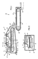
- the apparatus comprises a heating module 1 and a holding module 20.
- the heating module 1 includes a pervious conveyor 2, a plurality of closely spaced steam emitting nozzles 3 positioned below the conveyor 2, an outer removable enclosure 4, a rotatable feed valve 5, and a rotatable transfer valve 6.
- the holding module 20 comprises a holding conveyor 21 provided with a suitable heat insulating enclosure 22.
- the holding conveyor 21 comprises a plurality of receptacles 23 adapted to receive the heated food products from the heating module 1 through the rotary transfer valve 6.
- the heating module further comprises an inner enclosure 8 comprising a hood 9 positioned above the conveyor 2, and a lower removable portion 10 enclosing a region below the conveyor 2 including the nozzles 3.
- a conduit 11 interconnects the hood 9 and lower portion 10. Within the conduit is a circulating device, such as a fan 12.
- the inner enclosure 8 may take the form of separate units arranged serially along the conveyor.
- Figure 1 shows two such units 8 and 18. It will be understood that the inner enclosure may be in the form of a single integrated unit, or more than two units.
- the steam emitting nozzles. 3 are connected with a plurality of spaced transverse manifolds 13 under the upper loop of the pervious conveyor 2.
- Each of the manifolds 13 is connected to a longitudinal manifold 14 connected to a suitable source of pressurized steam (not shown).
- the food products are heated and agitated as the emitted steam contacts and condenses on the surface thereof.
- the inlet feed valve 5, as shown in Figure 1, is in the form of a rotary valve having multiple sealing vanes 15 and a feed hopper portion 17.
- the vanes 15 may include flexible outer and side portions to facilitate sealing and to provide greater safety in the event of inadvertent introduction of a hand at the hopper 17, as well as preventing damage to vegetal products.
- the feed valve may be insulated by a damping system from the remainder of the structure, so that a vibrator (not shown) may be connected to the feed valve 5 and/or the transfer valve 6 to facilitate egress of food products that do not flow readily.
- a temperature sensing device, or devices, positioned, for example, above the food products, in conjunction with a thermostatic controller may be used to modulate steam flow to the nozzles to provide consistent heating.
- the amount of steam supplied for a given apparatus will depend on the nature of the product and the type of processing desired, for example, blanching or cooking.
- the degree of product heating will be related to the rate of product introduction and speed of travel through the heating module 1.
- the spacing of the steam emitting nozzles from one another should be minimised. Furthermore, the spacing of nozzles is a factor in providing adequate agitation of mixing of the product for uniform heating of a multi-layer of product. It appears that a suitable range of nozzle spacing is from 5 to 10 cm.
- the nozzles should be placed as near as possible to the underside of the conveyor while avoiding mechanical interference.
- the speed of the transfer valve 6 will be an integral fraction of that of the conveyor 2 to accumulate the desired amount of product in each compartment 16.
- the rotary motion of the transfer valve 6 may be made intermittent to facilitate product transfer.
- the enclosures 4 and 23 preferably are provided with hinged or removable panels.
- the enclosures will preferably be well insulated to reduce heat loss.
- the food products to be processed are introduced into the heating module 1, by means of the feed valve 5.
- the rotating feed valve 5 deposits the products onto the pervious conveyor 2 in a multilayer, within the enclosure 4, to be transported through the inner enclosure 8, where heat is supplied.
- Steam supplied to the nozzles 3, by a suitable pressurised source at 14, is directed upwardly through the pervious conveyor 2.
- the jets of steam emitted from the nozzles 3 provide regions of relatively high energy steam flow, separated by relatively quiescent regions.
- each compartment 16 of the rotary transfer valve deposits a predetermined quantity consecutively into the receptacles 23 of the holding conveyor 21.
- the drive means for the conveyor is arranged such that the speed of travel of the pervious conveyor 2 is greater than that of the holding conveyor 21. This provides that the products in the holding receptacles are concentrated in relatively thick layer or bulk to retard heat loss and allow transfer of heat from the surface to the core of the individual product without further heat input. After completing travel in the holding conveyor 21, the products can be further processed in a conventional manner, such as freezing or canning, transported by a suitable conveyor 30.
- FIG 4 shows an alternate embodiment of the invention.
- the holding module 41 is shown disposed under the heating module 42. This configuration takes up less floor space.
- the receptacle meansforthe holding conveyor 43 is provided by a plurality of transverse dividers 44 disposed between side wall portions 45 on the conveyor.
- Figure 4 also shows an alternate feed valve 46.
- a reflective panel 47 may be used to reduce heat loss to the space below the conveyor.
- the apparatus may be provided with spray nozzles for product evacuation and cleaning and/ or for the addition of desired additives.
- a food processing apparatus that was constructed had an arrangement of nozzles similar to that illustrated in Figure 3.
- the nozzles 3 provided fan shaped jets oriented at 30° to an adjacent jet on the same transverse manifold 13.
- the nozzles were spaced approximately 5.7 cm apart along the manifold 13 and the transverse manifolds 13 were spaced approximately 8.3 cm apart along the longitudinal manifold 14.
- the nozzles were spaced approximately 1.3 cm below the pervious belt 2 which comprised double mesh stainless steel and being approximately 85% open. Pressures were varied from about 100 to 480 k Pa. While 310 k Pa was found to be suitable for most products, leafy products were best treated with lower pressures, and dense products at higher pressures.
Landscapes
- Engineering & Computer Science (AREA)
- Life Sciences & Earth Sciences (AREA)
- Chemical & Material Sciences (AREA)
- Food Science & Technology (AREA)
- Polymers & Plastics (AREA)
- Zoology (AREA)
- Wood Science & Technology (AREA)
- Chemical Kinetics & Catalysis (AREA)
- General Chemical & Material Sciences (AREA)
- Commercial Cooking Devices (AREA)
- Preparation Of Fruits And Vegetables (AREA)
- Baking, Grill, Roasting (AREA)
- General Preparation And Processing Of Foods (AREA)
- Apparatuses For Bulk Treatment Of Fruits And Vegetables And Apparatuses For Preparing Feeds (AREA)
Description
- This invention relates to processing food products with steam and particularly to an apparatus for continuous blanching or cooking of vegetal products.
- Steam blanching is known wherein vegetal products are carried on a perforated belt through a steam blanching chamber having water seals at each end. The known blanchers are inefficient in their use of energy, and the contact of the vegetal product with liquid water at an elevated temperature results in a loss of nutrients, flavour and textural properties, and is a source of high BOD ("Biological Oxygen Demand") effluent.
- It is known to blanch food products with steam using a pervious conveyor to convey the food products through a chamber where they are exposed to jets of steam issuing from a plurality of nozzles. However, to date, in order to provide uniform heating, the product to be treated has been distributed in a single layer on the conveyor as described for example, in U.S-A-3794500. This requirement limits the production rate and is inefficient in its use of energy.
- It has also been proposed (FR-A-2150533) to subject vegetable products to a different form of blanching in which steam emitting nozzles are not used. Rather, the food products to be treated are conveyed through a zone in which the combustion products from a gas burner are circulated, steam being injected into the combustion products as they circulate. Such an arrangement provides less control over the temperature and pressure of steam applied to the food products than an arrangement utilising steam-emitting nozzles directed at the products.
- An object of the invention is to provide an apparatus for blanching or cooking that allows efficient use of energy.
- Another object is to provide an apparatus that minimizes nutrient loss and effluent volume.
- It has been found that a relatively deep layer of food products, as distinct from a mono-layer, can be uniformly and efficiently heated with steam by using a plurality of closely spaced nozzles below the conveyor for emitting jets of steam into the product which agitate and mix the products while heating.
- The present invention provides an apparatus for processing food products with steam comprising a heating module and a holding module, said holding module comprising a holding conveyor having receptacle means for receiving heated food products from the heating module and holding the heated food products for a period of time at an elevated temperature, said heating module comprising an outer enclosure, a pervious conveyor within the enclosure, and steam-emitting nozzle means for heating food products on the conveyor, inlet means to the enclosure for depositing food products on the pervious conveyor, and transfer means for transferring heated food products from the heating module to the holding module, characterised in that the inlet means comprises a feed valve arranged to deposit a multilayer of food products on the pervious conveyor and in that the nozzle means comprises a plurality of upwardly-directed nozzles arranged below the pervious conveyor and spaced apart from each other to agitate food products on the pervious conveyor.
- The heating module may further comprise an inner enclosure including a hood portion positioned above the conveyor for collecting uncondensed steam and a lower portion enclosing a region below the conveyor including the steam nozzles, conduit means interconnecting the hood portion and lower portion, and means associated with the conduit for returning the collected uncondensed steam to the lower portion for recirculation through the conveyor and food products thereon.
- The present invention further provides a process for continuous treatment of food products comprising depositing food products on a pervious conveyor within a steam confining enclosure, heating the food products by steam jets, and transferring the heated products to a holding conveyor which travels at a speed lower than the pervious conveyor and depositing the products in a relatively thick layer on the holding conveyor within heat insulating enclosure means to allow continuation of heat treatment, characterised in that the food products are deposited in a multi- layer on the pervious conveyor and the heating of the food products is effected by directing a plurality of steam jets from below the pervious conveyor into the multilayer of food products to agitate the products, and in that uncondensed steam which has passed through the product is collected and recirculated through the pervious conveyor and food products. Advantageously, the products on the pervious conveyor are subjected to alternating stages of steam jet flow and a relatively quiescent stage as the pervious conveyor travels over the steam emitting nozzles thereby effecting vertical mixing of the product.
- By way of example, apparatus and a process in accordance with the present invention will now be described with reference to the accompanying drawings in which:
- Fig. 1 is a schematic elevation view of the apparatus
- Fig. 2 is a sectional view of the apparatus of Fig. 1 taken at 2-2
- Fig. 3 is a fragmented top view of the pervious conveyor revealing the arrangement of steam emitting nozzles and supply manifolds.
- Fig. 4 is a schematic elevation view showing an alternate embodiment of the present invention.
- With reference to Fig. 1, the apparatus comprises a heating module 1 and a
holding module 20. - The heating module 1 includes a
pervious conveyor 2, a plurality of closely spacedsteam emitting nozzles 3 positioned below theconveyor 2, an outerremovable enclosure 4, arotatable feed valve 5, and a rotatable transfer valve 6. - The
holding module 20 comprises aholding conveyor 21 provided with a suitableheat insulating enclosure 22. Theholding conveyor 21 comprises a plurality ofreceptacles 23 adapted to receive the heated food products from the heating module 1 through the rotary transfer valve 6. - With reference to both Figs. 1 and 2, the heating module further comprises an inner enclosure 8 comprising a
hood 9 positioned above theconveyor 2, and a lowerremovable portion 10 enclosing a region below theconveyor 2 including thenozzles 3. Aconduit 11 interconnects thehood 9 andlower portion 10. Within the conduit is a circulating device, such as afan 12. - The inner enclosure 8 may take the form of separate units arranged serially along the conveyor. Figure 1 shows two
such units 8 and 18. It will be understood that the inner enclosure may be in the form of a single integrated unit, or more than two units. - As shown in Figures 1, 2 and 3, the steam emitting nozzles. 3 are connected with a plurality of spaced
transverse manifolds 13 under the upper loop of thepervious conveyor 2. Each of themanifolds 13 is connected to alongitudinal manifold 14 connected to a suitable source of pressurized steam (not shown). The food products are heated and agitated as the emitted steam contacts and condenses on the surface thereof. - The
inlet feed valve 5, as shown in Figure 1, is in the form of a rotary valve having multiple sealingvanes 15 and afeed hopper portion 17. Thevanes 15 may include flexible outer and side portions to facilitate sealing and to provide greater safety in the event of inadvertent introduction of a hand at thehopper 17, as well as preventing damage to vegetal products. The feed valve may be insulated by a damping system from the remainder of the structure, so that a vibrator (not shown) may be connected to thefeed valve 5 and/or the transfer valve 6 to facilitate egress of food products that do not flow readily. - To provide control of the heating medium, a temperature sensing device, or devices, positioned, for example, above the food products, in conjunction with a thermostatic controller may be used to modulate steam flow to the nozzles to provide consistent heating. It will be understood that the amount of steam supplied for a given apparatus will depend on the nature of the product and the type of processing desired, for example, blanching or cooking. Also, the degree of product heating will be related to the rate of product introduction and speed of travel through the heating module 1.
- In order to maximise the throughput of the apparatus, the spacing of the steam emitting nozzles from one another should be minimised. Furthermore, the spacing of nozzles is a factor in providing adequate agitation of mixing of the product for uniform heating of a multi-layer of product. It appears that a suitable range of nozzle spacing is from 5 to 10 cm.
- For maximum efficiency, the nozzles should be placed as near as possible to the underside of the conveyor while avoiding mechanical interference.
- The speed of the transfer valve 6 will be an integral fraction of that of the
conveyor 2 to accumulate the desired amount of product in eachcompartment 16. The rotary motion of the transfer valve 6 may be made intermittent to facilitate product transfer. - To facilitate access to various components of the apparatus, the
enclosures - In operation, with reference to Figures 1 and 2, the food products to be processed are introduced into the heating module 1, by means of the
feed valve 5. Therotating feed valve 5 deposits the products onto thepervious conveyor 2 in a multilayer, within theenclosure 4, to be transported through the inner enclosure 8, where heat is supplied. Steam supplied to thenozzles 3, by a suitable pressurised source at 14, is directed upwardly through thepervious conveyor 2. The jets of steam emitted from thenozzles 3 provide regions of relatively high energy steam flow, separated by relatively quiescent regions. By subjecting the traversing products to the alternating high energy jets and quiescent periods, efficient agitation with vertical mixing of products is achieved which in turn provides uniform heat treatment of all products in a relatively thick layer. This contrasts with pervious systems wherein only a single layer of product was treated. - Steam that is not condensed after passing through the conveyor and products thereon, is collected by the
hood portion 9, and returned by means of thefan 12 through theconduit 11 to thelower portion 10 to be passed again through theconveyor 2. It should be noted that steam passing through the products comes from two sources, namely, the primary steam emitted directly from thenozzles 3, and the recirculated steam driven by the,fan 12. The use of the inner enclosure and recirculation provides more efficient transfer of heat energy to the products with less heat loss to theouter enclosure 4. Condensed steam collects below the conveyor and is removed atoutlet 19, via a steam trap. - After traversing the heating module 1, the heated products are transferred to the holding
module 20 by means of the transfer valve 6. Eachcompartment 16 of the rotary transfer valve deposits a predetermined quantity consecutively into thereceptacles 23 of the holdingconveyor 21. - The drive means for the conveyor is arranged such that the speed of travel of the
pervious conveyor 2 is greater than that of the holdingconveyor 21. This provides that the products in the holding receptacles are concentrated in relatively thick layer or bulk to retard heat loss and allow transfer of heat from the surface to the core of the individual product without further heat input. After completing travel in the holdingconveyor 21, the products can be further processed in a conventional manner, such as freezing or canning, transported by asuitable conveyor 30. - Figure 4 shows an alternate embodiment of the invention. The holding
module 41 is shown disposed under theheating module 42. This configuration takes up less floor space. The receptacle meansforthe holdingconveyor 43 is provided by a plurality oftransverse dividers 44 disposed betweenside wall portions 45 on the conveyor. Figure 4 also shows analternate feed valve 46. Areflective panel 47 may be used to reduce heat loss to the space below the conveyor. - The apparatus may be provided with spray nozzles for product evacuation and cleaning and/ or for the addition of desired additives.
- A food processing apparatus that was constructed had an arrangement of nozzles similar to that illustrated in Figure 3. The
nozzles 3 provided fan shaped jets oriented at 30° to an adjacent jet on the sametransverse manifold 13. The nozzles were spaced approximately 5.7 cm apart along the manifold 13 and thetransverse manifolds 13 were spaced approximately 8.3 cm apart along thelongitudinal manifold 14. The nozzles were spaced approximately 1.3 cm below thepervious belt 2 which comprised double mesh stainless steel and being approximately 85% open. Pressures were varied from about 100 to 480 k Pa. While 310 k Pa was found to be suitable for most products, leafy products were best treated with lower pressures, and dense products at higher pressures.
Claims (13)
Applications Claiming Priority (2)
| Application Number | Priority Date | Filing Date | Title |
|---|---|---|---|
| CA000384276A CA1162100A (en) | 1981-08-20 | 1981-08-20 | Food processing with steam |
| CA384276 | 1981-08-20 |
Publications (2)
| Publication Number | Publication Date |
|---|---|
| EP0073095A1 EP0073095A1 (en) | 1983-03-02 |
| EP0073095B1 true EP0073095B1 (en) | 1986-11-05 |
Family
ID=4120756
Family Applications (1)
| Application Number | Title | Priority Date | Filing Date |
|---|---|---|---|
| EP82303533A Expired EP0073095B1 (en) | 1981-08-20 | 1982-07-06 | Food processing with steam |
Country Status (8)
| Country | Link |
|---|---|
| US (1) | US4387630A (en) |
| EP (1) | EP0073095B1 (en) |
| JP (1) | JPS5832711A (en) |
| AU (1) | AU562986B2 (en) |
| CA (1) | CA1162100A (en) |
| DE (1) | DE3274050D1 (en) |
| DK (1) | DK295182A (en) |
| ES (1) | ES513245A0 (en) |
Families Citing this family (17)
| Publication number | Priority date | Publication date | Assignee | Title |
|---|---|---|---|---|
| US4473593A (en) * | 1982-03-15 | 1984-09-25 | Proctor & Schwartz | Process for preparing quick-cooking food products |
| JPS6053112A (en) * | 1983-08-31 | 1985-03-26 | 梶原工業株式会社 | Food continuous steamer |
| IT1192607B (en) * | 1983-10-03 | 1988-04-27 | Lorenzo Lucchetti | AUTOMATIC EQUIPMENT FOR COOKING DRIED FOOD-LEGUMES AND SIMILAR FOODS |
| JPS6352845A (en) * | 1986-08-20 | 1988-03-07 | Shinmei Seisakusho:Kk | Production of cereal rolled flake and apparatus therefor |
| JPH01107717A (en) * | 1987-10-19 | 1989-04-25 | Horiken Kogyo Kk | Steaming rice cooker |
| FI895684A0 (en) * | 1988-03-29 | 1989-11-28 | Gpki Rybopromy Flota | ANLAEGGNING FOER VAERMEBEHANDLING AV LIVSMEDEL. |
| US4942810A (en) * | 1988-09-15 | 1990-07-24 | Lyco Manufacturing, Inc. | Water seal blancher |
| DE4110817C1 (en) * | 1991-04-04 | 1993-01-21 | Roba B.V., Helmond, Nl | |
| US5666876A (en) * | 1991-12-20 | 1997-09-16 | Vos Industries Ltd. | Cooking apparatus |
| FR2698763B1 (en) * | 1992-12-07 | 1995-02-10 | Bonduelle Sa Ets | Method for heat treatment of food products, in particular for cooking vegetables, and device for its implementation. |
| US5947010A (en) * | 1997-09-30 | 1999-09-07 | Recot, Inc. | Chip de-oiler apparatus |
| US6263785B1 (en) | 1998-06-09 | 2001-07-24 | David R. Zittel | Blancher and method of operation |
| JP2002034482A (en) | 2000-07-28 | 2002-02-05 | Fuji Seisakusho:Kk | Gelatinizing device for noodles |
| FR2906975B1 (en) * | 2006-10-12 | 2011-12-30 | Bonduelle Sa Ets | METHOD FOR TREATING, IN PARTICULAR WHITENING AND / OR COOKING, FOOD PRODUCTS IN BULK |
| US8932658B2 (en) * | 2008-12-22 | 2015-01-13 | Laitram, L.L.C. | Method and apparatus for steam-cooking |
| KR101733857B1 (en) * | 2015-03-16 | 2017-05-08 | 씨제이제일제당 (주) | A steaming system for food processing |
| RU2727254C2 (en) * | 2015-10-27 | 2020-07-21 | Фелтрим Пасторал Компани ПиТиУай Лтд | Device for storage of organic material |
Family Cites Families (12)
| Publication number | Priority date | Publication date | Assignee | Title |
|---|---|---|---|---|
| DE509100C (en) * | 1930-10-04 | Herbort Kricheldorff & Brueser | Device for steaming and cooling vegetables u. like | |
| DE676309C (en) * | 1936-04-02 | 1939-06-01 | Karges Hammer Maschinenfabrik | Device for uninterrupted steaming of vegetables and fruits |
| US2534648A (en) * | 1945-06-12 | 1950-12-19 | Fmc Corp | Method of and apparatus for steaming vegetables |
| US2788735A (en) * | 1954-11-26 | 1957-04-16 | Stephen T Farace | Cooker for cylindrical food articles |
| US2917827A (en) * | 1958-02-14 | 1959-12-22 | Marion P Lankford | Continuous flow cheese making apparatus |
| US3537862A (en) * | 1967-02-01 | 1970-11-03 | Nestle Sa | Process for preparing an alimentary paste product |
| US3573938A (en) * | 1968-08-12 | 1971-04-06 | Amf Inc | Method and apparatus for dehydrating food foams |
| US3794500A (en) * | 1971-03-31 | 1974-02-26 | Us Agriculture | Deactivation of inner core enzymes by retained blanching heat |
| US3718082A (en) * | 1971-04-20 | 1973-02-27 | S Lipoma | Apparatus for continuous electromagnetic sterilization |
| US3801715A (en) * | 1971-08-25 | 1974-04-02 | G Hanscom | Dry blanching process |
| US4092911A (en) * | 1977-01-21 | 1978-06-06 | Goodale Richard J | Blanching apparatus |
| US4284359A (en) * | 1980-02-19 | 1981-08-18 | Theodore Rapolla | Agglomerization system for intermixing edible ingredients |
-
1981
- 1981-08-20 CA CA000384276A patent/CA1162100A/en not_active Expired
-
1982
- 1982-06-08 US US06/386,309 patent/US4387630A/en not_active Expired - Fee Related
- 1982-06-15 AU AU84884/82A patent/AU562986B2/en not_active Expired
- 1982-06-18 ES ES513245A patent/ES513245A0/en active Granted
- 1982-06-28 JP JP57111400A patent/JPS5832711A/en active Pending
- 1982-06-30 DK DK295182A patent/DK295182A/en not_active Application Discontinuation
- 1982-07-06 DE DE8282303533T patent/DE3274050D1/en not_active Expired
- 1982-07-06 EP EP82303533A patent/EP0073095B1/en not_active Expired
Also Published As
| Publication number | Publication date |
|---|---|
| AU562986B2 (en) | 1987-06-25 |
| EP0073095A1 (en) | 1983-03-02 |
| JPS5832711A (en) | 1983-02-25 |
| DK295182A (en) | 1983-02-21 |
| US4387630A (en) | 1983-06-14 |
| CA1162100A (en) | 1984-02-14 |
| AU8488482A (en) | 1983-02-24 |
| ES8400663A1 (en) | 1983-11-01 |
| ES513245A0 (en) | 1983-11-01 |
| DE3274050D1 (en) | 1986-12-11 |
Similar Documents
| Publication | Publication Date | Title |
|---|---|---|
| US4387630A (en) | Food processing with steam | |
| US4702161A (en) | Spray-type integrated vegetable blancher and cooler | |
| US4582047A (en) | High humidity steam cooker with continuously running conveyor | |
| EP0512061B1 (en) | Cooking oven and method for cooking of food products | |
| US3982481A (en) | Food processing apparatus | |
| US5243962A (en) | Cooking oven for slow-cooking of food products | |
| EP0650682B1 (en) | Apparatus for continuous high-volume steam cooking | |
| US6418834B1 (en) | Apparatus for treating an item during travel of the item along a treating trough | |
| US3910175A (en) | Dry blanching apparatus and process | |
| CA2087418C (en) | Continuous process cooker/blancher | |
| US2794326A (en) | Method and apparatus for cooling canned goods | |
| EP0498972B1 (en) | Method for blanching or part-cooking vegetable material | |
| WO2003073871A1 (en) | Airflow distribution systems for food processors | |
| US3469988A (en) | Continuous process for cooking food contained in hermetically sealed glass containers | |
| US4796523A (en) | Installation for the continuous heat treatment of foodstuffs | |
| US2836496A (en) | Method of cooking potato chips | |
| US3801715A (en) | Dry blanching process | |
| US5253569A (en) | Serpentine food processing with closed-loop recirculation | |
| US3087209A (en) | Container sterilizing apparatus | |
| US2144800A (en) | Pasteurizer | |
| JPS6147509B2 (en) | ||
| US4745935A (en) | Submerged nozzles in two-zone bath where conveyor belts pass through a slotted wall | |
| JPH0377509A (en) | Heat treatment method and equipment of food | |
| WO1987006811A1 (en) | Apparatus for boiling a product such as shrimps | |
| USRE34646E (en) | Apparatus for controlling pre-cooking and machine peeling shrimp |
Legal Events
| Date | Code | Title | Description |
|---|---|---|---|
| PUAI | Public reference made under article 153(3) epc to a published international application that has entered the european phase |
Free format text: ORIGINAL CODE: 0009012 |
|
| AK | Designated contracting states |
Designated state(s): BE DE FR GB IT NL SE |
|
| 17P | Request for examination filed |
Effective date: 19830830 |
|
| GRAA | (expected) grant |
Free format text: ORIGINAL CODE: 0009210 |
|
| AK | Designated contracting states |
Kind code of ref document: B1 Designated state(s): BE DE FR GB IT NL SE |
|
| PG25 | Lapsed in a contracting state [announced via postgrant information from national office to epo] |
Ref country code: BE Effective date: 19861105 |
|
| ITF | It: translation for a ep patent filed | ||
| PG25 | Lapsed in a contracting state [announced via postgrant information from national office to epo] |
Ref country code: SE Effective date: 19861130 |
|
| REF | Corresponds to: |
Ref document number: 3274050 Country of ref document: DE Date of ref document: 19861211 |
|
| ET | Fr: translation filed | ||
| PGFP | Annual fee paid to national office [announced via postgrant information from national office to epo] |
Ref country code: NL Payment date: 19870731 Year of fee payment: 6 |
|
| PLBE | No opposition filed within time limit |
Free format text: ORIGINAL CODE: 0009261 |
|
| STAA | Information on the status of an ep patent application or granted ep patent |
Free format text: STATUS: NO OPPOSITION FILED WITHIN TIME LIMIT |
|
| 26N | No opposition filed | ||
| PG25 | Lapsed in a contracting state [announced via postgrant information from national office to epo] |
Ref country code: NL Effective date: 19900201 |
|
| NLV4 | Nl: lapsed or anulled due to non-payment of the annual fee | ||
| ITTA | It: last paid annual fee | ||
| REG | Reference to a national code |
Ref country code: GB Ref legal event code: 732 |
|
| ITPR | It: changes in ownership of a european patent |
Owner name: CESSIONE;HER MAJESTY IN RIGHT OF CANADA AS REPRESE |
|
| REG | Reference to a national code |
Ref country code: FR Ref legal event code: TP |
|
| PGFP | Annual fee paid to national office [announced via postgrant information from national office to epo] |
Ref country code: DE Payment date: 20010917 Year of fee payment: 20 |
|
| PGFP | Annual fee paid to national office [announced via postgrant information from national office to epo] |
Ref country code: GB Payment date: 20010919 Year of fee payment: 20 |
|
| PGFP | Annual fee paid to national office [announced via postgrant information from national office to epo] |
Ref country code: FR Payment date: 20010925 Year of fee payment: 20 |
|
| REG | Reference to a national code |
Ref country code: GB Ref legal event code: IF02 |
|
| PG25 | Lapsed in a contracting state [announced via postgrant information from national office to epo] |
Ref country code: GB Free format text: LAPSE BECAUSE OF EXPIRATION OF PROTECTION Effective date: 20020705 |
|
| REG | Reference to a national code |
Ref country code: GB Ref legal event code: PE20 Effective date: 20020705 |