EP0072467A1 - Tablet coating apparatus - Google Patents
Tablet coating apparatus Download PDFInfo
- Publication number
- EP0072467A1 EP0072467A1 EP82106832A EP82106832A EP0072467A1 EP 0072467 A1 EP0072467 A1 EP 0072467A1 EP 82106832 A EP82106832 A EP 82106832A EP 82106832 A EP82106832 A EP 82106832A EP 0072467 A1 EP0072467 A1 EP 0072467A1
- Authority
- EP
- European Patent Office
- Prior art keywords
- end wall
- dragee
- fuselage
- coating drum
- coating
- Prior art date
- Legal status (The legal status is an assumption and is not a legal conclusion. Google has not performed a legal analysis and makes no representation as to the accuracy of the status listed.)
- Granted
Links
Images

Classifications
-
- A—HUMAN NECESSITIES
- A23—FOODS OR FOODSTUFFS; TREATMENT THEREOF, NOT COVERED BY OTHER CLASSES
- A23G—COCOA; COCOA PRODUCTS, e.g. CHOCOLATE; SUBSTITUTES FOR COCOA OR COCOA PRODUCTS; CONFECTIONERY; CHEWING GUM; ICE-CREAM; PREPARATION THEREOF
- A23G3/00—Sweetmeats; Confectionery; Marzipan; Coated or filled products
- A23G3/02—Apparatus specially adapted for manufacture or treatment of sweetmeats or confectionery; Accessories therefor
- A23G3/20—Apparatus for coating or filling sweetmeats or confectionery
- A23G3/26—Apparatus for coating by tumbling with a liquid or powder, spraying device-associated, drum, rotating pan
-
- A—HUMAN NECESSITIES
- A23—FOODS OR FOODSTUFFS; TREATMENT THEREOF, NOT COVERED BY OTHER CLASSES
- A23N—MACHINES OR APPARATUS FOR TREATING HARVESTED FRUIT, VEGETABLES OR FLOWER BULBS IN BULK, NOT OTHERWISE PROVIDED FOR; PEELING VEGETABLES OR FRUIT IN BULK; APPARATUS FOR PREPARING ANIMAL FEEDING- STUFFS
- A23N17/00—Apparatus specially adapted for preparing animal feeding-stuffs
-
- A—HUMAN NECESSITIES
- A61—MEDICAL OR VETERINARY SCIENCE; HYGIENE
- A61J—CONTAINERS SPECIALLY ADAPTED FOR MEDICAL OR PHARMACEUTICAL PURPOSES; DEVICES OR METHODS SPECIALLY ADAPTED FOR BRINGING PHARMACEUTICAL PRODUCTS INTO PARTICULAR PHYSICAL OR ADMINISTERING FORMS; DEVICES FOR ADMINISTERING FOOD OR MEDICINES ORALLY; BABY COMFORTERS; DEVICES FOR RECEIVING SPITTLE
- A61J3/00—Devices or methods specially adapted for bringing pharmaceutical products into particular physical or administering forms
- A61J3/005—Coating of tablets or the like
-
- B—PERFORMING OPERATIONS; TRANSPORTING
- B05—SPRAYING OR ATOMISING IN GENERAL; APPLYING FLUENT MATERIALS TO SURFACES, IN GENERAL
- B05B—SPRAYING APPARATUS; ATOMISING APPARATUS; NOZZLES
- B05B13/00—Machines or plants for applying liquids or other fluent materials to surfaces of objects or other work by spraying, not covered by groups B05B1/00 - B05B11/00
- B05B13/02—Means for supporting work; Arrangement or mounting of spray heads; Adaptation or arrangement of means for feeding work
- B05B13/0221—Means for supporting work; Arrangement or mounting of spray heads; Adaptation or arrangement of means for feeding work characterised by the means for moving or conveying the objects or other work, e.g. conveyor belts
- B05B13/025—Means for supporting work; Arrangement or mounting of spray heads; Adaptation or arrangement of means for feeding work characterised by the means for moving or conveying the objects or other work, e.g. conveyor belts the objects or work being present in bulk
- B05B13/0257—Means for supporting work; Arrangement or mounting of spray heads; Adaptation or arrangement of means for feeding work characterised by the means for moving or conveying the objects or other work, e.g. conveyor belts the objects or work being present in bulk in a moving container, e.g. a rotatable foraminous drum
Definitions
- the invention relates to a coating drum, the axis of rotation of which is at least approximately horizontal, with an at least approximately cylindrical fuselage and two at least approximately frustoconical end wall sections which adjoin one side of the fuselage.
- coating material such as granules, pellets, tablets or seeds are provided with one or more coatings by spraying a liquid coating composition onto the coating material or spraying it into the coating material while it is being kept in motion by the rotating coating drum.
- the aim is for coatings of uniform coating to form on all particles of the coating material, in particular of uniform thickness and density.
- Coating drums of the type described at the outset are known, for example from US Pat. No. 3,874,092, in which a front end wall section which tapers axially outwardly in the shape of a truncated cone adjoins a cylindrical fuselage on both sides.
- the coating material is generally only set in motion sufficiently vigorously and at the same time if baffles are formed on the inside of the fuselage, which prevent the coating material from sliding downwards on the inside of the fuselage even at moderate speeds of rotation of the coating drum .
- baffles can make cleaning the coating drum considerably more difficult, especially if the baffles have a changing shape or arrangement with which the mixing of the coating material is to be promoted.
- the invention is therefore based on the object of designing a coating drum in such a way that it can give the entire coating material contained therein a regular rolling or trickling movement with only poorly designed, easy-to-clean baffles, but preferably without any baffles.
- the object is achieved according to the invention in a coating drum of the type described in the introduction in that the two frustoconical end wall sections extend into the space enclosed by the fuselage.
- Rotation speed of the coating drum further and, above all, more uniformly in order to finally trickle down, partly as in known coating drums over the coating material coming up from below and partly over the frustoconical end wall sections projecting inwards according to the invention. Because part of the coating material constantly trickles over the inwardly projecting end wall sections, a mixing effect is additionally achieved which also contributes to the fact that all particles of the coating material receive particularly uniform coatings. Since any chicane can be dispensed with, the risk of the coatings being damaged can be kept particularly low.
- the coating drum according to the invention has the further advantage that, in comparison with known coating drums of the type described at the outset of the same hull diameter and the same overall axial width, it can accommodate a larger quantity of coating material and can process it uniformly in the manner described.
- the two frusto-conical end wall sections end in ring zones whose axial distance from one another is 30 to 70%, preferably 45 to 55%, of the width of the trunk.
- the interior of the coating drum, enclosed by the fuselage, is thus considerably constricted by the frustoconical end wall sections which are drawn inwards according to the invention.
- the diameter of the ring zones is advantageously 30 to 70%, preferably 45 to 55%, of the diameter of the body.
- the cone angles of the end wall sections are advantageously 60 to 120 °, preferably 80 to 100 °.
- One end section each can adjoin the ring zones and tapers axially outwardly in the shape of a truncated cone.
- Such end sections facilitate the filling of the coating material in a known manner and prevent particles of an unevenly introduced filling from escaping when the coating drum starts up.
- end sections are not necessary, since even with a strong coating material, it rarely happens that a particle of the coating material bounces off one of the ring zones in such a way that it could jump outwards.
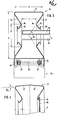
- the coating drum 10 shown in FIGS. 1 to 3 can be rotated about a horizontal axis of rotation A, has a cylindrical body 12 of width B and two annular end wall sections 14, each of which ends in an annular zone 16 coaxial with the axis of rotation A.
- the two ring zones 16 have an axial distance C from one another which is considerably smaller than the width B of the fuselage; 3, the distance C is approximately half the size of the width B.
- the ring zones 16 have a diameter E which, according to FIG. 3, is approximately half the size D of the fuselage 12.
- the cone angle oe of the end wall sections 14 is, according to FIG about 100 °.
- Each of the two ring zones 16 is adjoined by an end section 18 which tapers axially outward in the shape of a truncated cone and ends with a flange 20.
- the fuselage 12 is only approximately cylindrical, because it is composed of two fuselage parts 22 which taper slightly frustoconically with a cone angle ⁇ in the direction away from one another.
- a simple flanged edge 24 is provided, which immediately adjoins the adjacent ring zone 16 and delimits an opening which is correspondingly larger than that in FIG. 3 and in the left half of FIG. 4 each of openings 20 enclosed by one of the flanges.
- the opening on the right in FIG. 4 is covered with a cover 26, which is held in a known manner by mechanical fastening means and / or a negative pressure prevailing inside the coating drum 10.
- the coating drum 10 is mounted on a roller block 28 which has bearings 30 arranged in pairs with shafts 32 mounted therein, on the ends of which rollers 34 are fastened.
- One of the shafts 32 is connected in a conventional manner to a gear motor arranged inside the roller block 28.
- the rollers 34 are designed such that they not only support the coating drum 10 in the radial direction, but also guide it in the axial direction. For this purpose, it is not necessary for the fuselage 12 to be enclosed in the usual manner by annular rails, since the frusto-conical end wall sections 14 stiffen the fuselage 12 at its two edges in such a way that these can directly absorb the supporting forces transmitted by the rollers 34 . 1 to 3, an inlet air pipe 36, an outlet air pipe 38 and a spray line 40 extend parallel to the axis of rotation A into the coating drum 10.
- the supply air pipe 36 and the exhaust pipe 38 are perforated in the area between the levels of the two ring zones 16, and the spray medium line 40 in this area is equipped with nozzles 42 through which a spray medium, for example a sugar solution or a lacquer, onto a coating material contained in the coating drum 10 44 sprayed or sprayed into this coating material while the coating drum 10 rotates in the direction of arrow F in Fig.l.
- a spray medium for example a sugar solution or a lacquer
Landscapes
- Life Sciences & Earth Sciences (AREA)
- Chemical & Material Sciences (AREA)
- Engineering & Computer Science (AREA)
- Food Science & Technology (AREA)
- Polymers & Plastics (AREA)
- Health & Medical Sciences (AREA)
- Medicinal Chemistry (AREA)
- Pharmacology & Pharmacy (AREA)
- Animal Behavior & Ethology (AREA)
- General Health & Medical Sciences (AREA)
- Public Health (AREA)
- Veterinary Medicine (AREA)
- Medicinal Preparation (AREA)
- Medical Preparation Storing Or Oral Administration Devices (AREA)
- Coating Apparatus (AREA)
- Formation And Processing Of Food Products (AREA)
- Rigid Containers With Two Or More Constituent Elements (AREA)
- Tyre Moulding (AREA)
- Glanulating (AREA)
- Soil Working Implements (AREA)
- Display Devices Of Pinball Game Machines (AREA)
- Acyclic And Carbocyclic Compounds In Medicinal Compositions (AREA)
- Mechanical Pencils And Projecting And Retracting Systems Therefor, And Multi-System Writing Instruments (AREA)
- General Preparation And Processing Of Foods (AREA)
Abstract
Description
Die Erfindung betrifft eine Dragiertrommel, deren Drehachse zumindest annähernd waagerecht ist, mit einem zumindest annähernd zylindrischen Rumpf und zwei sich an je eine Seite des Rumpfes anschließenden, zumindest annähernd kegelstumpfförmigen Stirnwandabschnitten.The invention relates to a coating drum, the axis of rotation of which is at least approximately horizontal, with an at least approximately cylindrical fuselage and two at least approximately frustoconical end wall sections which adjoin one side of the fuselage.
In solchen Dragiertrommeln wird Dragiergut wie Granulat, Pellets, Tabletten oder auch Saatgut mit einem oder mehren Überzügen versehen, indem eine flüssige Überzugsmasse auf das Dragiergut aufgesprüht oder in das Dragiergut eingesprüht wird, während dieses von der sich drehenden Dragiertrommel in Bewegung gehalten wird. Dabei wird angestrebt, daß sich auf allen Partikeln des Dragierguts Uberzüge von gleichmäßiger Beschaffenheit, vorallem von gleichmäßiger Dicke und Dichte, bilden. Diese Eigenschaften sind beispielsweise bei solchen oral anwendbaren Arzneimitteln von Bedeutung, die gegen Magensaft resistent sein müssen, damit sie ihre Wirkstoffe erst im Darm freigeben.In such coating drums, coating material such as granules, pellets, tablets or seeds are provided with one or more coatings by spraying a liquid coating composition onto the coating material or spraying it into the coating material while it is being kept in motion by the rotating coating drum. The aim is for coatings of uniform coating to form on all particles of the coating material, in particular of uniform thickness and density. These properties are important, for example, in the case of such orally administrable medicinal products which have to be resistant to gastric juice so that they only release their active substances in the intestine.
Die Wahrscheinlichkeit, daß sich auf allen. Partikeln des Dragiergutes gleichmäßige Uberzüge bilden, ist dann am größten, wenn die einzelnen Partikel bei der Drehung der Dragiertrommel in regelmäßiger Folge übereinander hinwegrollen. Es muß also dafür gesorgt werden, daß die einzelnen Partikel des Dragiergutes von der sich drehenden Trommel im wesentlichen gleichmäßig über eine bestimmte Strecke nach oben mitgenommen und dann freigegeben werden, so daß sie wieder nach unten rieseln können.The likelihood that at all. Particles of the coating material form uniform coatings is greatest when the individual particles roll over one another in a regular sequence during the rotation of the coating drum. It must therefore be ensured that the individual particles of the coating material are taken up by the rotating drum substantially uniformly over a certain distance and then released so that they can trickle down again.
Es sind Dragiertrommeln der eingangs beschriebenen Gattung bekannt, beispielsweise aus der US-PS 3 874 092, bei denen sich an einen zylindrischen Rumpf beiderseits je ein sich kegelstumpfförmig axial nach außen verjüngender Stirnwandabschnitt anschließt. In solchen Dragiertrommeln wird das Dragiergut im allgemeinen nur dann genügend kräftig und zugleich schonend in Bewegung versetzt, wenn an der Innenseite des Rumpfes Schikanen ausgebildet sind, die das Dragiergut auch bei mäßigen Drehgeschwindigkeiten der Dragiertrommel daran-hindern, an der Innenseite des Rumpfes abwärts zu rutschen. Solche Schikanen können jedoch das Reinigen der Dragiertrommel wesentlich erschweren, vorallem wenn es sich um Schikanen wechselnder Form oder Anordnung handelt, mit denen die Durchmischung des Dragiergutes gefördert werden soll.Coating drums of the type described at the outset are known, for example from US Pat. No. 3,874,092, in which a front end wall section which tapers axially outwardly in the shape of a truncated cone adjoins a cylindrical fuselage on both sides. In such coating drums, the coating material is generally only set in motion sufficiently vigorously and at the same time if baffles are formed on the inside of the fuselage, which prevent the coating material from sliding downwards on the inside of the fuselage even at moderate speeds of rotation of the coating drum . However, such baffles can make cleaning the coating drum considerably more difficult, especially if the baffles have a changing shape or arrangement with which the mixing of the coating material is to be promoted.
Entsprechendes gilt auch für kugel- oder zwiebelförmige Dragiertrommeln, wie sie ebenfalls aus der US-PS 3 874 092 bekannt sind.The same applies to spherical or onion-shaped coating drums, as are also known from US Pat. No. 3,874,092.
Der Erfindung liegt deshalb die Aufgabe zugrunde, eine Dragiertrommel derart auszugestalten, daß sie mit-nur schwach ausgebildeten, leicht zu reinigenden Schikanen, vorzugsweise aber ohne jegliche Schikane dem gesamten in ihr enthaltenen Dragiergut eine regelmäßige rollende oder rieselnde Bewegung erteilen vermag.The invention is therefore based on the object of designing a coating drum in such a way that it can give the entire coating material contained therein a regular rolling or trickling movement with only poorly designed, easy-to-clean baffles, but preferably without any baffles.
Die Aufgabe ist bei einer Dragiertrommel der eingangs beschriebenen Gattung erfindungsgemäß dadurch gelöst, daß die beiden kegelstumpfförmigen Stirnwandabschnitte sich in den vom Rumpf umschlossenen Raum hineinerstrecken.The object is achieved according to the invention in a coating drum of the type described in the introduction in that the two frustoconical end wall sections extend into the space enclosed by the fuselage.
Damit wird erreicht, daß das Dragiergut sich zwischen den kegelstumpfförmigen Stirnwandabschnitten verspreizt, wodurch Reibungskräfte entstehen, die zusätzlich zu den durch die Schwerkraft hervorgerufenen, bei bekannten Dragiertrommeln allein wirksamen Reibungskräften bestrebt sind, das Dragiergut bei der Drehung der Trommel nach oben mitzunehmen. Das Dragiergut gelangt infolgedessen bei gegebenerThis ensures that the coating material spreads between the frusto-conical end wall sections, which creates frictional forces which, in addition to the frictional forces caused by gravity and which are only effective in known coating drums, aim to take the coating material upwards when the drum rotates. The As a result, coating material arrives at a given
Drehgeschwindigkeit der Dragiertrommel weiter und vorallem gleichmäßiger nach oben, um dann schließlich herabzurieseln, und zwar teilweise wie bei bekannten Dragiertrommeln über das von unten heraufkommende Dragiergut hinweg und zum anderen Teil über die erfindungsgemäß nach innen ragenden kegelstumpfförmigen Stirnwandabschnitte hinweg. Dadurch, daß ständig ein Teil des Dragiergutes über die nach innen ragenden Stirnwandabschnitte hinwegrieselt, wird zusätzlich ein Mischeffekt erzielt, der ebenfalls dazu beiträgt, daß alle Partikel des Dragiergutes besonders gleichmäßige Uberzüge erhalten. Da auf jegliche Schikane verzichtet werden kann, läßt sich auch die Gefahr, daß die Überzüge beschädigt werden, besonders gering halten.Rotation speed of the coating drum further and, above all, more uniformly in order to finally trickle down, partly as in known coating drums over the coating material coming up from below and partly over the frustoconical end wall sections projecting inwards according to the invention. Because part of the coating material constantly trickles over the inwardly projecting end wall sections, a mixing effect is additionally achieved which also contributes to the fact that all particles of the coating material receive particularly uniform coatings. Since any chicane can be dispensed with, the risk of the coatings being damaged can be kept particularly low.
.Die erfindungsgemäße Dragiertrommel hat den weiteren Vorteil, daß sie im Vergleich mit bekannten Dragiertrommeln der eingangs beschriebenen Gattung von gleichem Rumpfdurchmesser und gleicher axialer Gesamtbreite eine größere Menge Dragiergutes aufnehmen und in der beschriebenen Weise gleichmäßig verarbeiten kann.. The coating drum according to the invention has the further advantage that, in comparison with known coating drums of the type described at the outset of the same hull diameter and the same overall axial width, it can accommodate a larger quantity of coating material and can process it uniformly in the manner described.
Bei bevorzugten Ausführungsformen der erfindungsgemäßen Dragiertrommel enden die beiden kegelstumpfförmigen Stirnwandabschnitte in Ringzonen, deren axialer Abstand voneinander 30 bis 70%, vorzugsweise 45 bis 55%, der Breite des Rumpfes beträgt. Der vom Rumpf umschlossene Innenraum der Dragiertrommel erhält also durch die erfindungsgemäß nach innen gezogenen kegelstumpfförmigen Stirnwandabschnitte eine erhebliche Einschnürung.In preferred embodiments of the coating drum according to the invention, the two frusto-conical end wall sections end in ring zones whose axial distance from one another is 30 to 70%, preferably 45 to 55%, of the width of the trunk. The interior of the coating drum, enclosed by the fuselage, is thus considerably constricted by the frustoconical end wall sections which are drawn inwards according to the invention.
Der Durchmesser der Ringzonen beträgt zweckmäßigerweise 30 bis 70%, vorzugsweise 45 bis 55%, des Durchmessers des Rumpfes.The diameter of the ring zones is advantageously 30 to 70%, preferably 45 to 55%, of the diameter of the body.
Die Kegelwinkel der Stirnwandabschnitte (gemessen zwischen gegenüberliegenden Mantellinien) betragen zweckmäßigerweise 60 bis 120°, vorzugsweise 80 bis 100°.The cone angles of the end wall sections (measured between opposite surface lines) are advantageously 60 to 120 °, preferably 80 to 100 °.
An die Ringzonen kann sich je ein Endabschnitt anschließen, der sich axial nach außen kegelstumpfförmig verjüngt. Solche Endabschnitte erleichtern in bekannter Weise das Einfüllen des Dragiergutes und verhindern, daß Partikel einer ungleichmäßig eingebrachten Füllung beim Anlaufen der Dragiertrommel nach außen gelangen. Im Hinblick auf das normale Betriebsverhalten der erfindungsgemäßen Dragiertrommel sind solche Endabschnitte allerdings nicht erforderlich, da es selbst bei starker Dragiergutfüllung kaum vorkommt, daß ein Partikel des Dragiergutes von einer der Ringzonen derart abprallt, daß es nach außen springen könnte.One end section each can adjoin the ring zones and tapers axially outwardly in the shape of a truncated cone. Such end sections facilitate the filling of the coating material in a known manner and prevent particles of an unevenly introduced filling from escaping when the coating drum starts up. With regard to the normal operating behavior of the coating drum according to the invention, however, such end sections are not necessary, since even with a strong coating material, it rarely happens that a particle of the coating material bounces off one of the ring zones in such a way that it could jump outwards.
Ausführungsbeispiele der Erfindung werden im folgenden anhand schmematischer Zeichnungen beschrieben. Es zeigt:
- Fig.l eine Stirnansicht einer Dragieranlage mit einer erfin dungsgemäßen Dragiertrommel,
- Fig.2 die zugehörige Draufsicht,
- Fig.3 den Schnitt III-III in Fig.l und
- Fig.4 ein abgewandeltes Ausführungsbeispiel in einem der Fig.3 entsprechenden Teilschnitt.
- 1 is a front view of a coating system with a coating drum according to the invention,
- 2 the associated top view,
- 3 shows the section III-III in Fig.l and
- 4 shows a modified embodiment in a partial section corresponding to FIG.
Die in Fig.l bis 3 dargestellte Dragiertrommel 10 ist um eine waagerechte Drehachse A drehbar, hat einen zylindrischen Rumpf 12 von der Breite B sowie zwei ringförmige Stirnwandabschnitte 14, die in je einer zur Drehachse A koaxialen Ringzone 16 enden. Die beiden Ringzonen 16 haben voneinander einen axialen Abstand C, der erheblich kleiner als die Breite B des Rumpfes ist; gemäß Fig.3 ist der Abstand C ungefähr halbsogroß wie die Breite B. Die Ringzonen 16 haben einen Durchmesser E, der gemäß Fig.3 etwa halbsogroß ist wie der Durchmesser D des Rumpfes 12. Der Kegelwinkel oe der Stirnwandabschnitte 14 beträgt gemäß Fig.3 etwa 100°.The
An die beiden Ringzonen 16 schließt sich je ein Endabschnitt 18 an, der sich kegelstumpfförmig axial nach außen verjüngt und mit einem Flansch 20 endet.Each of the two
Das Vorstehende gilt im wesentlichen auch für das in Fig.4 dargestellte Ausführungsbeispiel. Hier ist der Rumpf 12 jedoch nur annähernd zylindrisch, denn er ist aus zwei Rumpfteilen 22 zusamnengesetzt, die sich leicht kegelstumpfförmig mit einem Kegelwinkel ß in Richtung voneinander weg verjüngen. Außerdem ist in Fig.4 anstelle eines der beiden in Fig.3 dargestellten Endabschnitte 18 mit zugehörigem Flansch 20 ein einfacher Bördelrand 24 vorgesehen, der sich unmittelbar an die benachbarte Ringzone 16 anschließt und eine öffnung umgrenzt, die entsprechend größer ist als die in Fig.3 sowie in der linken Hälfte der Fig.4 von je einem der Flansche 20 umschlossenen öffnungen. Die öffnung rechts in Fig.4 ist mit einem Deckel 26 abgedeckt, der in bekannter Weise von mechanischen Befestigungsmitteln und/oder einem im Inneren der Dragiertrommel 10 herrschenden Unterdruck festgehalten ist.The above applies essentially to the embodiment shown in FIG. Here, however, the
Gemäß Fig.1 bis 3 ist die Dragiertrommel 10 auf einem Rollenbock 28 gelagert, der paarweise angeordnete Lager 30 mit darin gelagerten Wellen 32 aufweist, an deren Enden Rollen 34 befestigt sind. Von den Wellen 32 ist eine in üblicher Weise mit i einem innerhalb des Rollenbocks 28 angeordneten Getriebemotor verbunden.1 to 3, the
Die Rollen 34 sind derart ausgebildet, daß sie die Dragiertrommel 10 nicht nur in radialer Richtung abstützen, sondern auch in axialer Richtung führen. Hierzu ist es nicht erforderlich, daß der Rumpf 12 in der üblichen Weise von ringförmigen Schienen umschlossen ist, denn die kegelstumpfförmig nach innen gezogenen Stirnwandabschnitte 14 versteifen den Rumpf 12 an seinen beiden Rändern derart, daß diese die von den Rollen 34 übertragenen Abstützkräfte unmittelbar aufnehmen können. Parallel zur Drehachse A erstrecken sich gemäß Fig.l bis 3 ein Zuluftrohr 36, ein Abluftrohr 38 und eine Sprühmittelleitung 40 in die Dragiertrommel 10 hinein. Zuluftrohr 36 und Abluftrohr 38 sind im Bereich zwischen den Ebenen der beiden Ringzonen 16 perforiert, und die Sprühmittelleitung 40 ist in diesem Bereich mit Düsen 42 besetzt, durch die ein Sprühmittel, beispielsweise eine Zuckerlösung oder ein Lack, auf ein in der Dragiertrommel 10 enthaltenes Dragiertgut 44 aufgesprüht oder in dieses Dragiergut eingesprüht werden kann, während die Dragiertrommel 10 sich in Richtung des Pfeils F in Fig.l dreht.The
Claims (8)
dadurch gekennzeichnet ,
daß die beiden kegelstumpfförmigen Stirnwandabschnitte (14) sich in den vom Rumpf (12) umschlossenen Raum hineinerstrecken.1. coating drum, whose axis of rotation (A) is at least approximately horizontal, with an at least approximately cylindrical fuselage (12) and two at least approximately frustoconical end wall sections (14) adjoining one side of the fuselage,
characterized ,
that the two frustoconical end wall sections (14) extend into the space enclosed by the fuselage (12).
dadurch gekennzeichnet ,
daß die beiden kegelstumpfförmigen Stirnwandabschnitte (14) in Ringzonen (16)'enden, deren axialer Abstand (C) voneinander 30 bis 70% der Breite (B) des Rumpfes (12) beträgt.2. coating drum according to claim 1,
characterized ,
that the two frustoconical end wall sections (14) end in ring zones (16) ' , the axial distance (C) of which is 30 to 70% of the width (B) of the fuselage (12).
dadurch gekennzeichnet,
daß der Abstand (C) der Ringzonen (16) voneinander 45 bis 55% der Breite (B) des Rumpfes (12) beträgt.3. coating drum according to claim 2,
characterized,
that the distance (C) of the ring zones (16) from one another is 45 to 55% of the width (B) of the fuselage ( 12 ).
dadurch gekennzeichnet ,
daß der Durchmesser (E) der Ringzonen (16) 30 bis 70% des Durchmessers (D) des Rumpfes (12) beträgt.4. coating drum according to claim 2 or 3,
characterized ,
that the diameter (E) of the ring zones (16) is 30 to 70% of the diameter (D) of the fuselage (12).
dadurch gekennzeichnet ,
daß der Durchmesser (E) der Ringzonen (16) 45 bis 55% des Durchmessers (D) des Rumpfes (12) beträgt.5. coating drum according to claim 4,
characterized ,
d ate the diameter (E) of the ring zones (16) is 45 to 55% of the diameter (D) of the fuselage (12).
dadurch gekennzeichnet ,
daß die Kegelwinkel (α) der Stirnwandabschnitte (14) 60 bis 120° betragen.6. coating drum according to one of claims 1 to 5,
characterized ,
that the cone angle (α) of the end wall sections (14) are 60 to 120 °.
dadurch gekennzeichnet ,
daß die Kegelwinkel (α) der Stirnwandabschnitte (14) 80 bis 100° betragen.7. coating drum according to claim 6,
characterized ,
that the cone angle (α) of the end wall sections (14) are 80 to 100 °.
dadurch gekennzeichnet ,
daß sich an die Ringzonen (16) je ein Endabschnitt (18) anschließt, der sich axial nach außen kegelstumpfförmig verjüngt.8. coating drum according to claim 2,
characterized ,
that each end section (18) adjoins the ring zones (16) and tapers axially outwardly in the shape of a truncated cone.
Priority Applications (1)
| Application Number | Priority Date | Filing Date | Title |
|---|---|---|---|
| AT82106832T ATE9869T1 (en) | 1981-07-30 | 1982-07-28 | DRAGING DRUM. |
Applications Claiming Priority (2)
| Application Number | Priority Date | Filing Date | Title |
|---|---|---|---|
| DE3130166 | 1981-07-30 | ||
| DE3130166A DE3130166C1 (en) | 1981-07-30 | 1981-07-30 | Coating drum |
Publications (2)
| Publication Number | Publication Date |
|---|---|
| EP0072467A1 true EP0072467A1 (en) | 1983-02-23 |
| EP0072467B1 EP0072467B1 (en) | 1984-10-17 |
Family
ID=6138152
Family Applications (1)
| Application Number | Title | Priority Date | Filing Date |
|---|---|---|---|
| EP82106832A Expired EP0072467B1 (en) | 1981-07-30 | 1982-07-28 | Tablet coating apparatus |
Country Status (14)
| Country | Link |
|---|---|
| US (1) | US4463703A (en) |
| EP (1) | EP0072467B1 (en) |
| JP (1) | JPS5820261A (en) |
| AT (1) | ATE9869T1 (en) |
| AU (1) | AU550339B2 (en) |
| CA (1) | CA1180951A (en) |
| DD (1) | DD202250A5 (en) |
| DE (2) | DE3130166C1 (en) |
| DK (1) | DK150924C (en) |
| ES (1) | ES274591Y (en) |
| HU (1) | HU184007B (en) |
| IE (1) | IE53491B1 (en) |
| NO (1) | NO154184C (en) |
| ZA (1) | ZA825446B (en) |
Cited By (3)
| Publication number | Priority date | Publication date | Assignee | Title |
|---|---|---|---|---|
| US4674198A (en) * | 1986-03-17 | 1987-06-23 | Huettlin Herbert | Apparatus for granulating, pelleting, and coating and/or drying fluid materials |
| DE3900773C1 (en) * | 1989-01-12 | 1989-08-24 | Herbert 7853 Steinen De Huettlin | |
| WO2005123267A1 (en) * | 2004-06-17 | 2005-12-29 | Gebr. Lödige Maschinenbau- Gesellschaft Mbh | Device and method for coating tablets by means of one rotatable drum |
Families Citing this family (9)
| Publication number | Priority date | Publication date | Assignee | Title |
|---|---|---|---|---|
| JPS63230079A (en) * | 1987-03-18 | 1988-09-26 | Toyobo Co Ltd | Aerating device for culture of large amount of animal cell |
| JP2554333B2 (en) * | 1987-06-10 | 1996-11-13 | 永柳工業 株式会社 | Hollow fiber gas separation membrane module made of silicone rubber |
| DE4005208C2 (en) * | 1990-02-20 | 1995-07-06 | Loedige Maschbau Gmbh Geb | Device with a drum rotating about an axis for coating material, in particular for film coating and / or sugar coating |
| JP3347767B2 (en) * | 1992-07-10 | 2002-11-20 | フロイント産業株式会社 | Bread coating equipment |
| DE4445618C2 (en) * | 1994-12-21 | 1997-09-04 | Loedige Maschbau Gmbh Geb | Device for film coating and / or sugar coating |
| US20030165614A1 (en) * | 2002-03-01 | 2003-09-04 | Henrik Hansen | Coating a medical implant using a pan coater |
| DE10345342A1 (en) * | 2003-09-19 | 2005-04-28 | Engelhard Arzneimittel Gmbh | Producing an ivy leaf extract containing hederacoside C and alpha-hederin, useful for treating respiratory diseases comprises steaming comminuted ivy leaves before extraction |
| US20070289157A1 (en) * | 2006-06-15 | 2007-12-20 | Chang Sung Pharmatech Co., Ltd | Dryer for medical Capsule |
| CN105769564A (en) * | 2014-12-25 | 2016-07-20 | 九芝堂股份有限公司 | Rolling tube type spraying mixing machine |
Citations (1)
| Publication number | Priority date | Publication date | Assignee | Title |
|---|---|---|---|---|
| FR2222957A1 (en) * | 1973-03-30 | 1974-10-25 | Glatt Werner |
Family Cites Families (2)
| Publication number | Priority date | Publication date | Assignee | Title |
|---|---|---|---|---|
| US550999A (en) * | 1895-12-10 | otten | ||
| US2807230A (en) * | 1954-03-11 | 1957-09-24 | Smith Kline French Lab | Apparatus for coating pills and tablets |
-
1981
- 1981-07-30 DE DE3130166A patent/DE3130166C1/en not_active Expired
-
1982
- 1982-06-07 CA CA000404634A patent/CA1180951A/en not_active Expired
- 1982-06-25 NO NO822143A patent/NO154184C/en not_active IP Right Cessation
- 1982-06-29 JP JP57110905A patent/JPS5820261A/en active Granted
- 1982-06-30 AU AU85455/82A patent/AU550339B2/en not_active Expired
- 1982-06-30 IE IE1586/82A patent/IE53491B1/en not_active IP Right Cessation
- 1982-07-13 DK DK313382A patent/DK150924C/en not_active IP Right Cessation
- 1982-07-14 US US06/398,082 patent/US4463703A/en not_active Expired - Lifetime
- 1982-07-17 ES ES1982274591U patent/ES274591Y/en not_active Expired
- 1982-07-19 DD DD82241762A patent/DD202250A5/en unknown
- 1982-07-28 AT AT82106832T patent/ATE9869T1/en not_active IP Right Cessation
- 1982-07-28 EP EP82106832A patent/EP0072467B1/en not_active Expired
- 1982-07-28 DE DE8282106832T patent/DE3261002D1/en not_active Expired
- 1982-07-29 ZA ZA825446A patent/ZA825446B/en unknown
- 1982-07-29 HU HU822436A patent/HU184007B/en unknown
Patent Citations (1)
| Publication number | Priority date | Publication date | Assignee | Title |
|---|---|---|---|---|
| FR2222957A1 (en) * | 1973-03-30 | 1974-10-25 | Glatt Werner |
Cited By (6)
| Publication number | Priority date | Publication date | Assignee | Title |
|---|---|---|---|---|
| US4674198A (en) * | 1986-03-17 | 1987-06-23 | Huettlin Herbert | Apparatus for granulating, pelleting, and coating and/or drying fluid materials |
| EP0238028A3 (en) * | 1986-03-17 | 1988-10-05 | Herbert Huttlin | Apparatus for granulating, pelletizing, making dragees of and/or drying pulverulent materials |
| DE3900773C1 (en) * | 1989-01-12 | 1989-08-24 | Herbert 7853 Steinen De Huettlin | |
| WO2005123267A1 (en) * | 2004-06-17 | 2005-12-29 | Gebr. Lödige Maschinenbau- Gesellschaft Mbh | Device and method for coating tablets by means of one rotatable drum |
| EP1607139A3 (en) * | 2004-06-17 | 2006-10-04 | Gebr. Lödige Maschinenbau Gesellschaft mbH | Device and method for coating of pills with a rotary drum |
| RU2359895C2 (en) * | 2004-06-17 | 2009-06-27 | Гебр. Лёдиге Машиненбау-Гезелльшафт Мбх | Device and method of coating tablets using revolving drum |
Also Published As
| Publication number | Publication date |
|---|---|
| NO154184C (en) | 1986-08-06 |
| ATE9869T1 (en) | 1984-11-15 |
| ES274591U (en) | 1984-05-16 |
| ES274591Y (en) | 1985-01-01 |
| IE821586L (en) | 1983-01-30 |
| DD202250A5 (en) | 1983-09-07 |
| JPS5820261A (en) | 1983-02-05 |
| AU550339B2 (en) | 1986-03-20 |
| DE3130166C1 (en) | 1982-11-11 |
| DK313382A (en) | 1983-01-31 |
| US4463703A (en) | 1984-08-07 |
| HU184007B (en) | 1984-06-28 |
| NO822143L (en) | 1983-01-31 |
| NO154184B (en) | 1986-04-28 |
| EP0072467B1 (en) | 1984-10-17 |
| DK150924B (en) | 1987-09-28 |
| CA1180951A (en) | 1985-01-15 |
| DE3261002D1 (en) | 1984-11-22 |
| ZA825446B (en) | 1983-06-29 |
| DK150924C (en) | 1988-03-14 |
| JPH0116550B2 (en) | 1989-03-24 |
| AU8545582A (en) | 1983-02-03 |
| IE53491B1 (en) | 1988-11-23 |
Similar Documents
| Publication | Publication Date | Title |
|---|---|---|
| DE2615520C2 (en) | Cyclone type water separator for a steam / water mixture | |
| EP0080199B1 (en) | Apparatus for treating a granular material by drying, film-coating or coating | |
| EP0072467B1 (en) | Tablet coating apparatus | |
| DE3032906C2 (en) | Rotary drum device for coating or sugar-coating of granular solid material | |
| EP0238028B1 (en) | Apparatus for granulating, pelletizing, making dragées of and/or drying pulverulent materials | |
| DE2707809C3 (en) | Device for coating granules | |
| EP0545044A2 (en) | Coating apparatus for lump products, particularly pills and tablets | |
| EP0294428A1 (en) | Cylinder discharge. | |
| DD144362A5 (en) | CIRCULAR DRUM OR PLATE FILTER | |
| DE2207663A1 (en) | CONTINUOUSLY WORKING SUGAR CENTRIFUGE | |
| CH290287A (en) | Process for mixing gases with liquids and equipment for carrying out this process. | |
| DE4118433A1 (en) | FLUID BED APPARATUS FOR TREATING PARTICLE-SHAPED GOODS | |
| DE3207869A1 (en) | DEVICE FOR COATING A PACKAGE | |
| EP0085290B1 (en) | Apparatus for discharging hot materials especially sponge iron from a shaft furnace | |
| DE2731351C3 (en) | Candy drum | |
| DE2751425A1 (en) | AIR ROTARY SORTER | |
| AT392016B (en) | DEVICE FOR GENERATING A DIRECTED SOLID FLOW IN FLUIDED LAYERS | |
| DE68902294T2 (en) | DEVICE FOR COATING POWDERY OR GRAINY SUBSTANCES. | |
| DE8122436U1 (en) | DRAG DRUM | |
| EP0237018A2 (en) | Apparatus for dewatering and drying solid materials, especially plastics pelletized below the water level | |
| DE2707921C3 (en) | Method and device for removing excess metal from dip-metallized objects | |
| DD140965A5 (en) | SAATGUTBEIZAPPARAT | |
| EP0603702B1 (en) | Apparatus for producing granules | |
| DE3434866C2 (en) | Immersion cooler for cooling and washing of flowing, dust-laden, hot gases | |
| EP0378110B1 (en) | Apparatus for granulating, pelletizing, coating and/or drying powdery materials |
Legal Events
| Date | Code | Title | Description |
|---|---|---|---|
| PUAI | Public reference made under article 153(3) epc to a published international application that has entered the european phase |
Free format text: ORIGINAL CODE: 0009012 |
|
| AK | Designated contracting states |
Designated state(s): AT BE CH DE FR GB IT LI NL SE |
|
| 17P | Request for examination filed |
Effective date: 19830316 |
|
| ITF | It: translation for a ep patent filed | ||
| GRAA | (expected) grant |
Free format text: ORIGINAL CODE: 0009210 |
|
| AK | Designated contracting states |
Designated state(s): AT BE CH DE FR GB IT LI NL SE |
|
| REF | Corresponds to: |
Ref document number: 9869 Country of ref document: AT Date of ref document: 19841115 Kind code of ref document: T |
|
| REF | Corresponds to: |
Ref document number: 3261002 Country of ref document: DE Date of ref document: 19841122 |
|
| ET | Fr: translation filed | ||
| PLBE | No opposition filed within time limit |
Free format text: ORIGINAL CODE: 0009261 |
|
| STAA | Information on the status of an ep patent application or granted ep patent |
Free format text: STATUS: NO OPPOSITION FILED WITHIN TIME LIMIT |
|
| 26N | No opposition filed | ||
| ITTA | It: last paid annual fee | ||
| EAL | Se: european patent in force in sweden |
Ref document number: 82106832.7 |
|
| PGFP | Annual fee paid to national office [announced via postgrant information from national office to epo] |
Ref country code: GB Payment date: 20010614 Year of fee payment: 20 |
|
| PGFP | Annual fee paid to national office [announced via postgrant information from national office to epo] |
Ref country code: CH Payment date: 20010618 Year of fee payment: 20 |
|
| PGFP | Annual fee paid to national office [announced via postgrant information from national office to epo] |
Ref country code: SE Payment date: 20010702 Year of fee payment: 20 |
|
| PGFP | Annual fee paid to national office [announced via postgrant information from national office to epo] |
Ref country code: AT Payment date: 20010704 Year of fee payment: 20 |
|
| PGFP | Annual fee paid to national office [announced via postgrant information from national office to epo] |
Ref country code: FR Payment date: 20010709 Year of fee payment: 20 |
|
| PGFP | Annual fee paid to national office [announced via postgrant information from national office to epo] |
Ref country code: BE Payment date: 20010713 Year of fee payment: 20 |
|
| PGFP | Annual fee paid to national office [announced via postgrant information from national office to epo] |
Ref country code: NL Payment date: 20010717 Year of fee payment: 20 |
|
| PGFP | Annual fee paid to national office [announced via postgrant information from national office to epo] |
Ref country code: DE Payment date: 20010822 Year of fee payment: 20 |
|
| BE20 | Be: patent expired |
Free format text: 20020728 *HUTTLIN HERBERT |
|
| REG | Reference to a national code |
Ref country code: GB Ref legal event code: IF02 |
|
| PG25 | Lapsed in a contracting state [announced via postgrant information from national office to epo] |
Ref country code: LI Free format text: LAPSE BECAUSE OF EXPIRATION OF PROTECTION Effective date: 20020727 Ref country code: GB Free format text: LAPSE BECAUSE OF EXPIRATION OF PROTECTION Effective date: 20020727 Ref country code: CH Free format text: LAPSE BECAUSE OF EXPIRATION OF PROTECTION Effective date: 20020727 |
|
| PG25 | Lapsed in a contracting state [announced via postgrant information from national office to epo] |
Ref country code: NL Free format text: LAPSE BECAUSE OF EXPIRATION OF PROTECTION Effective date: 20020728 Ref country code: AT Free format text: LAPSE BECAUSE OF EXPIRATION OF PROTECTION Effective date: 20020728 |
|
| REG | Reference to a national code |
Ref country code: GB Ref legal event code: PE20 Effective date: 20020727 |
|
| EUG | Se: european patent has lapsed |
Ref document number: 82106832.7 |
|
| REG | Reference to a national code |
Ref country code: CH Ref legal event code: PL |
|
| NLV7 | Nl: ceased due to reaching the maximum lifetime of a patent |
Effective date: 20020728 |