EP0072025A2 - Innenbrennkraftmaschine und Kraftstoffeinspritzungsteuersystem für eine Brennkraftmaschine - Google Patents
Innenbrennkraftmaschine und Kraftstoffeinspritzungsteuersystem für eine Brennkraftmaschine Download PDFInfo
- Publication number
- EP0072025A2 EP0072025A2 EP82107219A EP82107219A EP0072025A2 EP 0072025 A2 EP0072025 A2 EP 0072025A2 EP 82107219 A EP82107219 A EP 82107219A EP 82107219 A EP82107219 A EP 82107219A EP 0072025 A2 EP0072025 A2 EP 0072025A2
- Authority
- EP
- European Patent Office
- Prior art keywords
- fuel
- fuel injection
- driving
- injection valve
- internal combustion
- Prior art date
- Legal status (The legal status is an assumption and is not a legal conclusion. Google has not performed a legal analysis and makes no representation as to the accuracy of the status listed.)
- Granted
Links
Images

Classifications
-
- F—MECHANICAL ENGINEERING; LIGHTING; HEATING; WEAPONS; BLASTING
- F02—COMBUSTION ENGINES; HOT-GAS OR COMBUSTION-PRODUCT ENGINE PLANTS
- F02D—CONTROLLING COMBUSTION ENGINES
- F02D41/00—Electrical control of supply of combustible mixture or its constituents
- F02D41/30—Controlling fuel injection
- F02D41/32—Controlling fuel injection of the low pressure type
Definitions
- the present invention relates to an internal combustion engine and to a fuel injection control system for such an engine.
- the relationship between the driving time and the amount of fuel injected is non-linear in the case of a normal fuel injection valve.
- a conventional fuel injection system is constructed on the assumption that the relationship is linear. As a result, the quantities of fuel injection are not optimized.
- a fuel injection control system for an internal combustion engine provided with a fuel injection valve and characterised by: fuel flow calculation means for calculating a fuel flow amount in accordance with predetermined operating parameters of said engine; memory means having an address input coupled to an output of said calculation means, said memory means storing values of a driving time for corresponding values applied to said address input from said calculation means; and drive means for driving said fuel injection valve with driving times determined in accordance with values supplied from said memory means.
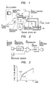
- Figure 1 shows an arithmetic control system 3 which receives, as operating parameters, both (1) the output of an engine speed detecting device 7, which generates a pulse each time the crankshaft (not shown) of the engine rotates through a predetermined angle, e.g. one- pulse at each intake stroke of the engine, and (2) the output of an intake air flow rate detecting device, such as a pressure sensor 2 disposed in an intake manifold of the engine downstream of a throttle valve 5.
- the arithmetic control system.3 calculates an approximate driving time of a fuel injection valve 4, disposed downstream of an air cleaner 1, which injects fuel into a cylinder 6 in synchronization with the rotation of the engine.
- fuel pressurized by a fuel pump 9 is supplied from a fuel tank 10 through a fuel pressure regulator 8 by way of a fuel line 13 to the fuel injection valve 4.
- the fuel pressure regulator 8 is connected by a line 14 to the intake manifold at a point adjacent the fuel injection valve 4 so that the pressure at the injecting position of the fuel injection valve 4 may be used as the operating pressure of the fuel pressure regulator 8.
- Pressurized excess fuel is returned to the fuel tank 10 via a fuel line 12. With the described arrangement, the pressures upstream and downstream of the injection valve 4 are held at predetermined levels.
- a sawtooth wave generating circuit 20 is triggered by the output of the engine speed detecting device 7.
- the output of the sawtooth wave generating circuit 20 is connected to one input terminal of a comparator 30, the other input terminal of which is connected to the output of the pressure sensor 2 which generates a voltage which is linearly proportional to the absolute pressure in the intake manifold downstream of the throttle valve 5.
- the comparator 30 outputs a signal which drives (opens) the fuel injection valve 4 when the output of the sawtooth wave generating circuit 20 is lower than the output of the pressure sensor 2, with the driving of the fuel injection valve 4 commencing from the time the sawtooth wave generating circuit 20 is triggered by the output of the engine speed detecting device 7.
- the output of the comparator 30 is applied to the fuel injection valve 4 through a driver 40.
- This system is constructed and operated upon the assumption that a linear relationship exists among the intake air flow rate, the absolute pressure in the intake manifold, the output voltage of the pressure sensor 2 and the effective driving time of the injection valve 4 during one intake stroke of the engine, and also that a linear relationship exists between the effective driving time of the fuel injection valve 4 and the amount of fuel injected.
- the amount of fuel injected from the fuel injection valve 4 in one operation is dependent upon the effective area of the valve, the open time of the valve and the pressure of the fuel supplied thereto. Of these parameters, the effective area of the valve is assumed to be invariant. Therefore, if the fuel pressure is held constant, theoretically a linear relationship exists between the effective driving time of the fuel injection valve and the amount of fuel injected.
- the areas A, B and C under the curve in Figure 4 represent the total amount of fuel injected by the valve in the corresponding time periods. It is the existence of the areas A and C for the periods from t 2 to t 3 and from t 4 to t 5 which make the actual relationship between the driving time of the valve and the amount of fuel injected non-linear.
- the presence of the areas A and C is unaffected by changing the theoretical fixed effective area of the valve, the fuel pressure, or the fuel line size.
- the fuel injection valve would have to be opened and closed at an infinite speed, which is clearly impossible for a valve body having a finite inertia. Moreover, even a significant reduction of to would require a very expensive injection valve and driver.
- a practical fuel injection valve must have a minimum injection (open) period determined by the maximum rotational speed of the engine. Specifically, the valve should be able to open and close about five times within the period defined by t i -t 0 in Figure 3.
- t i -t 0 it is difficult as a practical matter to construct a fuel injection valve which meets this criteria.
- prior art fuel injection systems used a plurality of injection valves or they operated the injection valve only outside of the non-linear region. This was accompanied by a difficulty that the air-to-fuel ratio could not be precisely controlled.
- the embodiment of the invention shown in Figure 5 provides a fuel injection system for an internal combustion engine in which effective driving times for the fuel injection valve are prestored in a memory 60.
- the injection valve 4 is driven in accordance with the output of the memory 60 so that no error is present in the air-to-fuel ratio of the intake mixture even when the non-linear region of the injection valve 4 is used.
- no expensive injection valve, plural injection valves, or expensive driver are needed as in the prior art.
- a fuel flow arithmetic unit or calculation means 50 calculates a desired fuel flow amount in accordance with the flow rate of intake air as indicated by the output of the pressure sensor 2 which detects the pressure in the intake manifold for each intake stroke of the engine.
- the memory 60 receives the output of the fuel flow arithmetic unit 50 as an address input and, in response thereto, supplies numerical values representing the actual driving time of the fuel injection valve.
- the memory 60 may be implemented with a ROM (Read Only Memory) or other non-volatile memory device. Elements 50 and 60 may together be implemented by a single IC device 87AD manufactured by Nippon Electric Co., Ltd.
- a driving signal generating circuit 70 generates driving signal pulses which have a time width determined according to the output values from the memory 60 and which are in synchronization with the pulses of the output signal from the aforementioned engine speed detecting device 7.
- This device 70 may consist of an Intel 8253 programmable counter. The output from the driving signal generating circuit is applied by the driver 40 to the valve 4.
- the fuel flow arithmetic unit 50 in response to the output of the pressure sensor 2, provides output values such that a predetermined desired air-to-fuel ratio is maintained, that is, the proper amount of fuel is injected during each intake stroke, taking into account non-linearities in the characteristics of the fuel injection valve. More specifically the memory 60 is pre-programmed with numerical values representative of the driving time - amount of fuel injected characteristic curve of the injection valve 4. An example of such a curve is shown as a curve c in Figure 6.
- the memory 60 For instance, for a calculated fuel amount Ql, the memory 60 outputs a driving time value t 6 (non-linear region), and for a calculated fuel amount Q2, the memory 60 outputs a driving time t 7 (linear region).
- the driving signal generating circuit 70 generates driving signal pulses according to the driving time values t 6 , t 7' etc. applied thereto from the memory 60, in synchronization with the pulses from the engine speed detecting device 7 which occur at each intake stroke of the engine.
- the cylinder 6 of the engine is fed with a mixture having a precisely controlled air-to-fuel ratio.
- the present invention is not limited to a fuel injection system used with an internal combustion engine in which injection is synchronized with the intake timing, but can also be applied to systems in which the injection valve is driven at a frequency proportional to the flow rate of intake air.
Landscapes
- Engineering & Computer Science (AREA)
- Chemical & Material Sciences (AREA)
- Combustion & Propulsion (AREA)
- Mechanical Engineering (AREA)
- General Engineering & Computer Science (AREA)
- Electrical Control Of Air Or Fuel Supplied To Internal-Combustion Engine (AREA)
Applications Claiming Priority (2)
| Application Number | Priority Date | Filing Date | Title |
|---|---|---|---|
| JP56125632A JPS5827822A (ja) | 1981-08-10 | 1981-08-10 | 内燃機関用燃料噴射制御装置 |
| JP125632/81 | 1981-08-10 |
Publications (3)
| Publication Number | Publication Date |
|---|---|
| EP0072025A2 true EP0072025A2 (de) | 1983-02-16 |
| EP0072025A3 EP0072025A3 (en) | 1983-06-22 |
| EP0072025B1 EP0072025B1 (de) | 1986-11-12 |
Family
ID=14914844
Family Applications (1)
| Application Number | Title | Priority Date | Filing Date |
|---|---|---|---|
| EP82107219A Expired EP0072025B1 (de) | 1981-08-10 | 1982-08-10 | Innenbrennkraftmaschine und Kraftstoffeinspritzungsteuersystem für eine Brennkraftmaschine |
Country Status (6)
| Country | Link |
|---|---|
| US (1) | US4719572A (de) |
| EP (1) | EP0072025B1 (de) |
| JP (1) | JPS5827822A (de) |
| KR (1) | KR870001682B1 (de) |
| AU (1) | AU555035B2 (de) |
| DE (1) | DE3274278D1 (de) |
Cited By (1)
| Publication number | Priority date | Publication date | Assignee | Title |
|---|---|---|---|---|
| EP0771942A1 (de) * | 1995-10-30 | 1997-05-07 | Bayerische Motoren Werke Aktiengesellschaft, Patentabteilung AJ-3 | Vorrichtung zur elektronischen Steuerung der Brennkraftmaschine in Kraftfahrzeugen mit einem Einspritzventil |
Families Citing this family (3)
| Publication number | Priority date | Publication date | Assignee | Title |
|---|---|---|---|---|
| US5092301A (en) * | 1990-02-13 | 1992-03-03 | Zenith Fuel Systems, Inc. | Digital fuel control system for small engines |
| US6202629B1 (en) | 1999-06-01 | 2001-03-20 | Cummins Engine Co Inc | Engine speed governor having improved low idle speed stability |
| US6463913B1 (en) * | 2000-06-30 | 2002-10-15 | Ford Global Technologies, Inc. | Fuel control system |
Family Cites Families (14)
| Publication number | Priority date | Publication date | Assignee | Title |
|---|---|---|---|---|
| US3838397A (en) * | 1973-04-25 | 1974-09-24 | Rockwell International Corp | Fuel injection pulse width computer |
| GB1528744A (en) * | 1974-10-25 | 1978-10-18 | Lucas Electrical Ltd | Fuel injection systems for internal combustion engines |
| JPS5514907B2 (de) * | 1975-03-07 | 1980-04-19 | ||
| DE2539113B2 (de) * | 1975-09-03 | 1978-04-20 | Robert Bosch Gmbh, 7000 Stuttgart | Elektronische Einrichtung zur Steuerung eines periodisch sich wiederholenden Vorganges bei Brennkraftmaschinen, insbesondere des Stauflusses durch die Zündspule |
| IT1081383B (it) * | 1977-04-27 | 1985-05-21 | Magneti Marelli Spa | Apparecchiatura elettronica per il controllo dell'alimentazione di una miscela aria/benzina di un motore a combustione interna |
| CA1119493A (en) * | 1978-07-21 | 1982-03-09 | Mamoru Fujieda | Fuel injection system for internal combustion engine |
| US4196702A (en) * | 1978-08-17 | 1980-04-08 | General Motors Corporation | Short duration fuel pulse accumulator for engine fuel injection |
| DE2900420A1 (de) * | 1979-01-08 | 1980-07-24 | Bosch Gmbh Robert | Einrichtung zum steuern des stromes durch einen elektromagnetischen verbraucher, insbesondere durch ein elektromagnetisch betaetigbares einspritzventil einer brennkraftmaschine |
| US4355620A (en) * | 1979-02-08 | 1982-10-26 | Lucas Industries Limited | Fuel system for an internal combustion engine |
| JPS598656B2 (ja) * | 1979-03-15 | 1984-02-25 | 日産自動車株式会社 | 燃料噴射装置 |
| JPS55131535A (en) * | 1979-04-02 | 1980-10-13 | Honda Motor Co Ltd | Engine controller |
| JPS569633A (en) * | 1979-07-02 | 1981-01-31 | Hitachi Ltd | Control of air-fuel ratio for engine |
| JPS56159530A (en) * | 1980-05-13 | 1981-12-08 | Diesel Kiki Co Ltd | Injection controller for fuel injection valve of internal- combustion engine |
| JPS575526A (en) * | 1980-06-11 | 1982-01-12 | Diesel Kiki Co Ltd | Method of detecting injection flow in fuel injection valve |
-
1981
- 1981-08-10 JP JP56125632A patent/JPS5827822A/ja active Pending
-
1982
- 1982-05-28 KR KR8202369A patent/KR870001682B1/ko not_active Expired
- 1982-08-10 EP EP82107219A patent/EP0072025B1/de not_active Expired
- 1982-08-10 DE DE8282107219T patent/DE3274278D1/de not_active Expired
- 1982-08-10 AU AU87026/82A patent/AU555035B2/en not_active Ceased
-
1985
- 1985-07-26 US US06/758,848 patent/US4719572A/en not_active Expired - Lifetime
Cited By (1)
| Publication number | Priority date | Publication date | Assignee | Title |
|---|---|---|---|---|
| EP0771942A1 (de) * | 1995-10-30 | 1997-05-07 | Bayerische Motoren Werke Aktiengesellschaft, Patentabteilung AJ-3 | Vorrichtung zur elektronischen Steuerung der Brennkraftmaschine in Kraftfahrzeugen mit einem Einspritzventil |
Also Published As
| Publication number | Publication date |
|---|---|
| DE3274278D1 (en) | 1987-01-02 |
| US4719572A (en) | 1988-01-12 |
| EP0072025A3 (en) | 1983-06-22 |
| JPS5827822A (ja) | 1983-02-18 |
| AU8702682A (en) | 1983-05-12 |
| AU555035B2 (en) | 1986-09-11 |
| KR830010287A (ko) | 1983-12-30 |
| EP0072025B1 (de) | 1986-11-12 |
| KR870001682B1 (ko) | 1987-09-22 |
Similar Documents
| Publication | Publication Date | Title |
|---|---|---|
| US4359032A (en) | Electronic fuel injection control system for fuel injection valves | |
| US4265200A (en) | Method and apparatus for controlling the onset of fuel injection in diesel engines | |
| EP0142101B1 (de) | Fahrzeugmotorsteuersystem mit der Fähigkeit den Betriebszustand des Motors zu vermitteln und das passende Betriebsschema zu wählen | |
| US5355859A (en) | Variable pressure deadheaded fuel rail fuel pump control system | |
| US4565173A (en) | Method and system for controlling fuel to be supplied from fuel pump to engine | |
| US5586538A (en) | Method of correcting engine maps based on engine temperature | |
| EP0147026A2 (de) | Kraftstoffeinspritzvorrichtung | |
| GB1590342A (en) | Method and apparatus for the determination of operating parameters in an internal combustion engine | |
| BR9501935A (pt) | Distema integrado de controle eletrônico para um sistema de injeção de combustível em motor de combustão interna | |
| EP0130382A1 (de) | Kraftstoff-Einspritzverfahren für einen Motor | |
| US4530332A (en) | Fuel control system for actuating injection means for controlling small fuel flows | |
| US4442815A (en) | Optimum air-fuel ratio control for internal combustion engine | |
| EP0219843B1 (de) | Verfahren und System für Leerlaufdrehzahlsteuerung | |
| US5950598A (en) | Method for determining the injection time for a direct-injection internal combustion engine | |
| US4312038A (en) | Electronic engine control apparatus having arrangement for detecting stopping of the engine | |
| US4550705A (en) | Electrical fuel injector | |
| US4639870A (en) | Fuel supply control method for internal combustion engines, with adaptability to various engines and controls therefor having different operating characteristics | |
| EP0072025A2 (de) | Innenbrennkraftmaschine und Kraftstoffeinspritzungsteuersystem für eine Brennkraftmaschine | |
| EP0153497B1 (de) | Kraftstoffeinspritzungssystem, im Drosselgehäuse eingebaut mit verbreitertem Verwendungsbereich | |
| US4643147A (en) | Electronic fuel injection with fuel optimization and exhaust pressure feedback | |
| US4509487A (en) | Fuel system for multi-cylinder engine | |
| GB2110756A (en) | A fuel injection system for internal combustion engines | |
| US5873350A (en) | Method for adapting the delay time of an electromagnetic tank-venting valve | |
| US4404945A (en) | Fuel-supply control system for gas-turbine engine | |
| US5033439A (en) | Injection supply device for internal combustion engine, with electronic control |
Legal Events
| Date | Code | Title | Description |
|---|---|---|---|
| PUAI | Public reference made under article 153(3) epc to a published international application that has entered the european phase |
Free format text: ORIGINAL CODE: 0009012 |
|
| AK | Designated contracting states |
Designated state(s): DE FR GB |
|
| PUAL | Search report despatched |
Free format text: ORIGINAL CODE: 0009013 |
|
| AK | Designated contracting states |
Designated state(s): DE FR GB |
|
| 17P | Request for examination filed |
Effective date: 19830913 |
|
| GRAA | (expected) grant |
Free format text: ORIGINAL CODE: 0009210 |
|
| AK | Designated contracting states |
Kind code of ref document: B1 Designated state(s): DE FR GB |
|
| REF | Corresponds to: |
Ref document number: 3274278 Country of ref document: DE Date of ref document: 19870102 |
|
| ET | Fr: translation filed | ||
| PLBI | Opposition filed |
Free format text: ORIGINAL CODE: 0009260 |
|
| 26 | Opposition filed |
Opponent name: SIEMENS AKTIENGESELLSCHAFT, BERLIN UND MUENCHEN Effective date: 19870810 |
|
| PLBN | Opposition rejected |
Free format text: ORIGINAL CODE: 0009273 |
|
| STAA | Information on the status of an ep patent application or granted ep patent |
Free format text: STATUS: OPPOSITION REJECTED |
|
| 27O | Opposition rejected |
Effective date: 19920401 |
|
| PGFP | Annual fee paid to national office [announced via postgrant information from national office to epo] |
Ref country code: GB Payment date: 19980803 Year of fee payment: 17 |
|
| PGFP | Annual fee paid to national office [announced via postgrant information from national office to epo] |
Ref country code: FR Payment date: 19980814 Year of fee payment: 17 |
|
| PG25 | Lapsed in a contracting state [announced via postgrant information from national office to epo] |
Ref country code: GB Free format text: LAPSE BECAUSE OF NON-PAYMENT OF DUE FEES Effective date: 19990810 |
|
| GBPC | Gb: european patent ceased through non-payment of renewal fee |
Effective date: 19990810 |
|
| PG25 | Lapsed in a contracting state [announced via postgrant information from national office to epo] |
Ref country code: FR Free format text: LAPSE BECAUSE OF NON-PAYMENT OF DUE FEES Effective date: 20000428 |
|
| REG | Reference to a national code |
Ref country code: FR Ref legal event code: ST |
|
| PGFP | Annual fee paid to national office [announced via postgrant information from national office to epo] |
Ref country code: DE Payment date: 20010806 Year of fee payment: 20 |
|
| APAH | Appeal reference modified |
Free format text: ORIGINAL CODE: EPIDOSCREFNO |