EP0071384A2 - Dispositif de déminage monté sur véhicule - Google Patents
Dispositif de déminage monté sur véhicule Download PDFInfo
- Publication number
- EP0071384A2 EP0071384A2 EP82303792A EP82303792A EP0071384A2 EP 0071384 A2 EP0071384 A2 EP 0071384A2 EP 82303792 A EP82303792 A EP 82303792A EP 82303792 A EP82303792 A EP 82303792A EP 0071384 A2 EP0071384 A2 EP 0071384A2
- Authority
- EP
- European Patent Office
- Prior art keywords
- vehicle
- orientation
- frame
- tooth
- raised
- Prior art date
- Legal status (The legal status is an assumption and is not a legal conclusion. Google has not performed a legal analysis and makes no representation as to the accuracy of the status listed.)
- Granted
Links
- 230000000977 initiatory effect Effects 0.000 claims 1
- 230000000712 assembly Effects 0.000 description 4
- 238000000429 assembly Methods 0.000 description 4
- 230000006835 compression Effects 0.000 description 3
- 238000007906 compression Methods 0.000 description 3
- 238000010276 construction Methods 0.000 description 3
- 230000005484 gravity Effects 0.000 description 2
- 238000009434 installation Methods 0.000 description 2
- 230000035515 penetration Effects 0.000 description 2
- 230000003014 reinforcing effect Effects 0.000 description 2
- 239000002689 soil Substances 0.000 description 2
- 230000008878 coupling Effects 0.000 description 1
- 238000010168 coupling process Methods 0.000 description 1
- 238000005859 coupling reaction Methods 0.000 description 1
- 230000006837 decompression Effects 0.000 description 1
- 230000000694 effects Effects 0.000 description 1
- 230000002250 progressing effect Effects 0.000 description 1
Images


Classifications
-
- F—MECHANICAL ENGINEERING; LIGHTING; HEATING; WEAPONS; BLASTING
- F41—WEAPONS
- F41H—ARMOUR; ARMOURED TURRETS; ARMOURED OR ARMED VEHICLES; MEANS OF ATTACK OR DEFENCE, e.g. CAMOUFLAGE, IN GENERAL
- F41H11/00—Defence installations; Defence devices
- F41H11/12—Means for clearing land minefields; Systems specially adapted for detection of landmines
- F41H11/16—Self-propelled mine-clearing vehicles; Mine-clearing devices attachable to vehicles
- F41H11/20—Self-propelled mine-clearing vehicles; Mine-clearing devices attachable to vehicles with ground-penetrating elements, e.g. with means for removing buried landmines from the soil
- F41H11/24—Self-propelled mine-clearing vehicles; Mine-clearing devices attachable to vehicles with ground-penetrating elements, e.g. with means for removing buried landmines from the soil the elements being ploughs
-
- E—FIXED CONSTRUCTIONS
- E02—HYDRAULIC ENGINEERING; FOUNDATIONS; SOIL SHIFTING
- E02F—DREDGING; SOIL-SHIFTING
- E02F3/00—Dredgers; Soil-shifting machines
- E02F3/04—Dredgers; Soil-shifting machines mechanically-driven
- E02F3/76—Graders, bulldozers, or the like with scraper plates or ploughshare-like elements; Levelling scarifying devices
- E02F3/7609—Scraper blade mounted forwardly of the tractor on a pair of pivoting arms which are linked to the sides of the tractor, e.g. bulldozers
- E02F3/7613—Scraper blade mounted forwardly of the tractor on a pair of pivoting arms which are linked to the sides of the tractor, e.g. bulldozers with the scraper blade adjustable relative to the pivoting arms about a vertical axis, e.g. angle dozers
-
- E—FIXED CONSTRUCTIONS
- E02—HYDRAULIC ENGINEERING; FOUNDATIONS; SOIL SHIFTING
- E02F—DREDGING; SOIL-SHIFTING
- E02F3/00—Dredgers; Soil-shifting machines
- E02F3/04—Dredgers; Soil-shifting machines mechanically-driven
- E02F3/76—Graders, bulldozers, or the like with scraper plates or ploughshare-like elements; Levelling scarifying devices
- E02F3/80—Component parts
- E02F3/815—Blades; Levelling or scarifying tools
- E02F3/8157—Shock absorbers; Supports, e.g. skids, rollers; Devices for compensating wear-and-tear, or the like
-
- F—MECHANICAL ENGINEERING; LIGHTING; HEATING; WEAPONS; BLASTING
- F41—WEAPONS
- F41H—ARMOUR; ARMOURED TURRETS; ARMOURED OR ARMED VEHICLES; MEANS OF ATTACK OR DEFENCE, e.g. CAMOUFLAGE, IN GENERAL
- F41H11/00—Defence installations; Defence devices
- F41H11/12—Means for clearing land minefields; Systems specially adapted for detection of landmines
- F41H11/16—Self-propelled mine-clearing vehicles; Mine-clearing devices attachable to vehicles
- F41H11/28—Self-propelled mine-clearing vehicles; Mine-clearing devices attachable to vehicles using brushing or sweeping means or dozers to push mines lying on a surface aside; using means for removing mines intact from a surface
Definitions
- the present invention relates to apparatus for clearing mines, and more particularly to mine clearing apparatus mountable on an armoured vehicle such as a tank.
- the present invention seeks to overcome disadvantages and limitations of prior art mine clearing apparatus and provides mine clearing apparatus for attachment to a vehicle comprising a frame mountable onto a vehicle for selectable positioning in a raised or lowered orientation; apparatus for raising and shunting aside mines mounted onto the frame, and apparatus for selectably retaining the frame in a raised orientation and comprising control apparatus operable from inside the vehicle for releasing the frame from the raised orientation and allowing it to assume the lowered orientation.
- the apparatus for raising and shunting aside mines comprises a plurality of plow teeth which, in operation, extend below the ground surface and first and second plow sections, disposed one above another in hinged engagement and operative to lie in the same plane during operation and in folded engagement when the frame is in its raised orientation, so as not to interfere with normal tank operation.
- the raising and shunting apparatus also comprises a gliding surface which supports the frame in its lowered orientation.
- the gliding surface is provided with a front mine deflector plate for deflecting mines in the path thereof.
- the gliding surface may be provided with a retaining member so as to prevent inadvertent engagement of the gliding surface with treads of its supporting vehicle under certain conditions of terrain.
- apparatus for clearing mines comprising a frame mountable onto a vehicle for selectable positioning in a raised or lowered orientation, plow apparatus for raising and shunting aside mines mounted onto the frame and apparatus for automatically raising the plow from its lowered orientation to its raised orientation in response to backwards motion of the vehicle and including mounting apparatus rotatably mounted onto the vehicle, spring supporting apparatus mounted onto the mounting apparatus and attached to the plow apparatus, and tooth apparatus fixed onto the mounting apparatus and arranged for selectable engagement with a vehicle.tread, the spring supporting apparatus being operative when the plow is in its lowered orientation to urge the tooth apparatus into driven engagement with the vehicle tread whereby during backwards movement of the vehicle the mounting apparatus rotates in a first direction, thereby extending the length of the spring supporting apparatus, and increasing the spring force thereof until a spring force is reached at a first position of the mounting apparatus sufficient to raise the plow to its raised orientation.
- the spring supporting apparatus comprises first and second springs having different spring constants arranged in a series arrangement.
- At least one of the springs comprises a disk or belleville spring.
- the tooth apparatus comprises two teeth, one of which engages the vehicle treads when the frame is in the lowered orientation upon the onset of backwards motion and the other of which becomes disengaged from the vehicle treads upon traversal of the third position, in order to permit spring driven rotation of mounting apparatus.
- Figs. 1 - 3 illustrate mine clearing apparatus constructed and operative in accordance with an embodiment of the present invention.
- the present description is presented with particular reference to mine 0 clearing apparatus which is mountable onto-a particular type of tank, the M-60 Patton. It is appreciated that this is entirely for the purpose of illustration and that the invention is applicable to other types of tanks and possibly other vehicles as well.
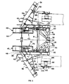
- the mine clearing apparatus comprises a frame 10 including a pair of identical side portions 12 which are joined at their front end by a cross bar 14 and at their rear end support an axle 16.
- Frame 10 is rigidly mounted onto an armoured vehicle such as a M-60 tank in the illustrated embodiment by engagement of pins 17 located at side portions 12 with towline lugs fixed onto the tank.
- Ridigity of mounting is provided by bolts 18 which engage the underside of the tank and force mounting plates 20, fixedly mounted onto side portions 12 on the opposite side of pins 17, into tight engagement with the underside hull of the tank.
- First and second arms 22 and 24 are independently rotatably mounted onto axle 16 and extend forwardly thereof in generally parallel planes. Arms 22 and 24 are strengthened by reinforcing elements 26 and 28 respectively which are fixed at one end thereof to the respective arms and are rotatably mounted by means of clamps 30 and 32 onto axle 16.
- Mine plowing assembly 34 comprises main plow portion 36, of generally elongate configuration and concave cross section.
- main plow portion 36 may be similar to that of an ordinary vehicle powered snow plow. Disposed above main plow portion 36 and hinged thereonto is an auxiliary plow portion 38. Auxiliary plow portion 38 has two positions, a lowered position in which it extends forwardly of the surface of main plow portion 36 and a raised position in which it defines an upper continuation of the surface of the main plow portion 36.
- This hinged construction is to obviate the problem of interference with a driver's field of vision or with the range of operation of the armament on a tank.
- the hinged auxiliary plow portion 38 may be lowered when the plowing assembly 34 is in its raised orientation.
- main plow portion 36 Disposed below main plow portion 36 there are provided a plurality of vertically disposed planar blades 40, . which during operation are disposed below the ground surface. .
- the horizontal spacing between adjacent vertical blades is selected to be such that anti-vehicle mines will of necessity be engaged thereby.
- the blades are provided with an inclined forward surface, so as to raise mines located under the ground surface into engagement with main plow portion 36, so that they may be plowed aside.
- a desired depth of operation for blades 40 is determined by means of a gliding surface assembly 42 which is articulatedly mounted onto each of arms 22 and 24.
- the gliding surface assembly 42 comprises a sled 44 which is arranged to slide on the ground surface and is formed at its front with a vertical blade 47 for deflecting mines to the side thereof.
- Sled 44 is rotatably mounted onto a cam slot of a mounting plate 46.
- Mounting plate 46 is mounted in turn onto a mounting element 48. It is appreciated that sled 44 is permitted to undergo a somewhat complex articulated motion in a single plane within limits defined by the respective cam paths.
- This mounting arrangement permits selectable adjustment of the penetration depth of the plowing assembly 34 and also permits the sled 44 to be folded when : the plowing assembly is in its raised orientation to eliminate interference with operation of the tank.
- a chain 50 extends from each auxiliary plow portion 38 to a location on the tank hull or onto frame 10.
- the length of the chain 50 is selected such that it is slack when the plowing assembly is in its raised orientation but becomes tight when the plowing assembly is lowered, thus pulling on auxiliary plow portion 38 and orienting it towards a generally vertical orientation.
- the full raised orientation of the auxiliary plow portion 38 is reached only when soil being plowed is forced thereagainst.
- a hook member 60 is pivotably mounted about an axis 62 onto each side portion 12 and comprises a socket portion 64 located at one end thereof and a roller portion 66 at another end thereof and having mounted thereon a roller 68.
- a selectable release lever 70 is pivotably mounted onto each side portion 12 about an axis 72 and defines first and second roller support shoulders 74 and 76.
- a spring 78 joins hook member 60 and release lever 70, urging lever 70 into seating engagement with roller 68 at one of shoulders 74 and 76.
- a cable connection 80 is provided to the interior of the vehicle, such that pulling on the cable is operative to provide counter-clockwise movement of lever 70 about its pivot axis 72 (as seen in Figs. 4A and 4B).
- Fig. 4B shows a retainer roller 82 which is fixedly mounted onto each of arms 22 and 24 about to engage socket portion 64 and moving in an arc illustrated by an arrow 84. Engagement of roller 82 with a surface 86 of the socket portion forces the hook member to pivot in a clockwise direction about its pivot axis 62 (in the sense of Figs. 4A and 4B).
- roller 68 Due to the action of roller 68 against hook member 60, and the subsequent tendency of hook member 60 to rotate in a counterclockwise direction in response to the effect of gravity on roller 82 and the massive plowing assembly attached thereto, roller 68 seats on shoulder 76 and is thus prevented from further counterclockwise rotation into an open orientation.
- Roller 82 is thus securely engaged by hook member 60 and arms 22 and 24 are maintained in their respective raised orientation, provided that lever 70 remains in the seated position (Fig. 4A).
- the apparatus for automatically lifting the mine plowing assembly comprises a freely rotatable disk 90 which is bearing mounted onto a mounting member 92 which is bolted onto a tension wheel 94 of a tank. Tension wheel 94 engages the tread of the tank and maintains it at a desired tension. Mounted on an outer facing surface of disk 90 are three outer pins 95, 96 and 97 and an inner disposed pin 98. Mounted on an inner facing surface of disk 90 is a tooth 100 which is disposed ordinarily out of engagement with corresponding interstices defined between plates of the tank tread.
- a lifting chain 99 which is attached at its other end to a location 102 fixed onto main plow portion 36.
- a spring 104 which is attached at its other end to main plow portion 36.
- Spring 104 is operative when in the orientation illustrated in Fig. 2 to urge disk to rotate about its axis 91 in a clockwise direction (in the sense of Fig. 2). This rotation brings tooth 100 into driven engagement with corresponding interstices between plates of the tank tread. As soon as the tank is moving forward, this engagement produces only a clicking action as engagement with the interstices between the plates of the tank tread tend to move the tooth 100 in a counterclockwise direction, while the spring 104 snaps the tooth back in a clockwise direction.
- the apparatus for automatically lifting the mine plowing assembly described above is operative upon reverse motion of the tank with the mine plowing assembly in a lowered orientation.
- tooth 100 engages one of the interstices between adjacent plates thereof and is driven together with disk 90 in a clockwise direction thereby causing chain 99 to wind about pins 96 and 97, with the result that the chain pulls the plowing assembly 34 upwardly until roller 82 engages hook member 60 in locked engagement for retaining the arm and associated plowing assembly in a raised orientation.
- tooth 100 engages one of the interstices of the tread plates and is moved in a counterclockwise direction until it reaches a location at which the treads tend to disengage therewith. Since the orientation . of spring 104 has passed its dead spot due to the raised orientation of plowing assembly 34, spring 104 is operative to urge the tooth 100 and disk 90 to undertake further counter- clockwise motion until tooth 100 is totally disengaged from the tank treads. This orientation remains until the plowing assembly is lowered, at which time, spring 104 is again reoriented and urges the disk 90 into the orientation shown in Fi g . 2.
- a limit chain 110 is provided for attachment between frame 10 and each of arms 22 and 24 to prevent arms 22 and 24 from falling beyond a certain limit in the event that a sudden drop in the ground level is encountered, as such a drop could otherwise bring the plowing assembly into engagement with the tank treads.
- the plowing assembly engages the ground surface in the vicinity of the treads and outwardly thereof.
- a weighted chain 120 is mounted between the two plowing assemblies to engage and detonate any mines that are encountered at a safe distance from the tank.
- FIG. 5 - 9 illustrate an alternate embodiment of the mine clearing apparatus constructed and operative in accordance with the present invention.
- Like numerals in Figs. 5 - 9 and Figs. 1 -4 indicate like elements.
- the mine clearing apparatus of Figs. 5 - 9 also comprises a frame 10 including a pair of identical side portions 12 which are joined at their front end by a cross bar 14 and at their rear end support an axle 16.
- Frame 10 is rigidly mounted onto an armoured vehicle such as an M-60 tank in the illustrated embodiment by engagement of pins 17 located at side portions 12 with towline lugs fixed onto the tank. Rigidity of mounting is provided by bolts 18 which engage the underside of the.tank and force mounting plates 20, fixedly mounted onto side portions 12 on the opposite side of pins 17, into tight engagement with the underside hull of the tank.
- First and second arms 22 and 24 are independently rotatably mounted onto axle 16 and extend forwardly thereof in generally parallel planes. Arms 22 and 24 are strengthened by reinforcing elements 26 and 28 respectively which are fixed at one end thereof to the respective arms and are rotatably mounted by means of clamps 30 and 32 onto axle 16.
- Mine plowing assembly 34 comprises main plow portion 36 which is substantially identical to that described in connection with Figs. 1 - 4. Disposed above main plow portion 36 and hinged thereonto is an auxiliary plow portion 38, substantially identical with that described hereinabove.
- main plow portion 36 Disposed below main plow portion 36 there are provided a plurality of vertically disposed planar blades 40, . whic during operation are disposed below the ground surface.
- the horizontal spacing between adjacent vertical blades is selected to be such that anti-vehicle mines will, of necessity, . be engaged thereby.
- the blades are provided with an inclined forward surface, so as to raise mines located under the ground surface into engagement with main plow portion 36, so that they may be plowed aside.
- a desired-depth of operation for blades 40 is determined by means of a gliding surface assembly 42 which is articulatedly mounted onto each of arms 22 and 24.
- the gliding surface assembly 42 comprises a sled 44 which is arranged to slide on the ground surface and is formed at its front with a vertical blade 45 for deflecting mines to the 0 side thereof.
- Sled 44 is rotatably mounted onto a cam slot of a mounting plate 46.
- Mounting plate 46 is mounted in turn onto a mounting element 48. It is appreciated that sled 44 is permitted to undergo a somewhat complex articulated motion in a single plane within limits defined by the respective cam paths.
- This mounting arrangement permits selectable adjustment of the penetration depth of the plowing assembly 34 and also permits the sled 44 to be folded when the plowing assembly is in its raised orientation to eliminate interference with operation of the tank.
- a chain 50 extends from each auxiliary plow portion 38 to a location on the tank hull.
- the length of the chain 50 is selected such that it is slack when the plowing assembly is in its raised orientation but becomes tight when the plowing assembly is lowered, thus pulling on auxiliary plow portion 38 and orienting it towards a generally vertical orientation.
- the full raised orientation of the auxiliary plow portion 38 is reached only when soil being plowed is forced thereagainst.
- the locking mechanism of Figs. 4A and.4B also act as described hereinabove with the apparatus of Figs. 5 - 9 to retain the arms in their raised orientation and to selectably release them.
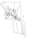
- the apparatus for automatically lifting the mine plowing assembly comprises a freely rotatable disk segment 190 which is bearing mounted onto a mounting member 192 which is bolted onto a tension wheel 194 of a tank. Tension wheel 194 engages the tread of the tank and maintains it as a desired tension.
- Mounted on an edge surface of disk segment 190 are first and second spaced teeth 196 and 198 which selectably engage the interstices defined between plates of the tank tread in accordance with an embodiment of the invention.
- Spring supporting apparatus 199 comprises a spring housing 200 which is" rotatably mounted at a first end thereof onto mounting pin 195 and a spring compressing rod 205 which is connected at an exterior end thereof to a location 202 fixed . onto the main plow portion 36.
- Spring supporting apparatus 199 may be generally described as comprising a spring loaded extensible support member formed of elements 200 and 205 and comprising first and second springs 201 and 203 arranged in a series arrangement.
- Springs 201 and 203 preferably have greatly different spring forces.
- spring 201 is an ordinary heavy duty coil spring while spring 203 comprises a series of independent disk or belleville springs which are characterized in that they undergo complete compression at a compressive force of about 7 ton. It is appreciated that any other suitable spring arrangement may be employed alternatively and that the arrangement.of apparatus 199 is such that extension of apparatus 199 produces compression of springs 201 and 203.
- disk segment 190 In order to understand the operation of the automatic lifting apparatus, it is necessary to appreciate the details of construction of disk segment 190 and the relative positions of teeth 196 and 198 and pin 195 thereon.
- the direction of motion of the tank treads during reverse motion of the tank is indicated by an arrow 204.
- the disk segment 190 Upon engagement of at least one teeth 196 and 198 with the tank treads, the disk segment 190 is caused to rotate in a clockwise direction, indicated by an arrow 206 about pivot location 193.
- pin 195 leads tooth 196 by about 20° and tooth 196 leads tooth 198 by about 90°.
- Fig. 6-- shows the plowing assembly in a fully lowered plowing orientation prior to engagement of tooth 196 with the tank treads.
- spring 201 is compressed to about one-half of its maximum length. This is the orientation during forward mine clearing operation of the tank.
- the tank When it is desired to raise the mine clearing apparatus to a raised orientation, the tank simply shifts to reverse motion. Due to the position of tooth 196 which is pressed against the tank tread during motion in a forward direction as illustrated in Fig. 6, reverse motion of the tank tread in a direction indicated by arrow 204, tends to draw tooth 196 into driven engagement therewith, causing clockwise rotation of disk segment 1.90 in a direction indicated by arrow 207. An initial backwards movement of the tank causes the blades 40 to lie on the ground surface instead of being buried partially therebelow.
- a series combination of a relatively weak spring 201 and a relatively strong spring 203 are employed in spring support apparatus 199 for a number of reasons.
- One reason is to present a relatively weak spring- force during plowing operation so as not to force tooth 196. against the tank tread with excessive force during plowing operations which could cause excessive wear of tooth 196.
- a second reason is not to cause inadvertent disengagement of the plowing apparatus from the.soi1 due to the force of spring support apparatus 199.
- the strong spring 203 is, however, predominant during the lifting operation. As seen in Fig. 7, the weak spring 201 is quickly fully compressed at the beginning of the lifting operation and this is neutralized, allowing the spring force of the strong spring 203 to predominate.
- the disk segment 190 With continued backwards movement of the tank treads, the disk segment 190 continues to rotate due to the engagement of tooth 198 with the treads, even after tooth 196 becomes disengaged therefrom. This continued rotation combined with the immobility of the plowing assembly due to its raised locked orientation cuases spring 203 to become compressed. Maximum compression occurs at an orientation illustrated in Fig. 8, wherein the longitudinal axis of spring supporting apparatus 199 intersects the axis of rotation of disk segment 190 at pivot location 193.
- the orientation illustrated in Fig. 8 represents a dead point at which the spring supporting apparatus does not urge rotation of the disk segment 190 in either direction. Once disk segment 190 moves even slightly over the dead point orientation of Fig. 8, the spring force of the spring supporting apparatus 199 urges clockwise rotation of the disk segment 190.
- the click of decompression of the springs 201 and 203 provides a noise sensible to the driver of the tank, indicating to him that he can commence forward motion of the tank with the plowing assembly in a raised orientation.
- a limit chain is provided for attachment between frame 10 and each of arms 22 and 24 to prevent arms 22 and 24 from falling beyond a certain limit in the event that a sudden drop in the ground level is encountered, as such a drop could otherwise bring the plowing assembly into engagement with the tank treads.
- the plowing assembly engages the ground surface in the vicinity of the treads and outwardly thereof.
- a weighted chain 120 is mounted between the two plowing assemblies to engage and detonate any mines that are encountered at a safe distance from the tank.
Landscapes
- Engineering & Computer Science (AREA)
- General Engineering & Computer Science (AREA)
- Mechanical Engineering (AREA)
- Mining & Mineral Resources (AREA)
- Civil Engineering (AREA)
- Structural Engineering (AREA)
- Life Sciences & Earth Sciences (AREA)
- Soil Sciences (AREA)
- Soil Working Implements (AREA)
- Agricultural Machines (AREA)
Priority Applications (1)
| Application Number | Priority Date | Filing Date | Title |
|---|---|---|---|
| AT82303792T ATE19823T1 (de) | 1981-07-27 | 1982-07-19 | Auf einem fahrzeug gelagerte minenraeumvorrichtung. |
Applications Claiming Priority (4)
| Application Number | Priority Date | Filing Date | Title |
|---|---|---|---|
| IL63437A IL63437A (en) | 1981-07-27 | 1981-07-27 | Mine-field clearing apparatus mountable on a vehicle |
| IL63437 | 1981-07-27 | ||
| IL64023 | 1981-10-09 | ||
| IL64023A IL64023A0 (en) | 1981-10-09 | 1981-10-09 | Mine-field clearing apparatus mountable on a vehicle |
Publications (3)
| Publication Number | Publication Date |
|---|---|
| EP0071384A2 true EP0071384A2 (fr) | 1983-02-09 |
| EP0071384A3 EP0071384A3 (en) | 1983-06-22 |
| EP0071384B1 EP0071384B1 (fr) | 1986-05-14 |
Family
ID=26320943
Family Applications (1)
| Application Number | Title | Priority Date | Filing Date |
|---|---|---|---|
| EP82303792A Expired EP0071384B1 (fr) | 1981-07-27 | 1982-07-19 | Dispositif de déminage monté sur véhicule |
Country Status (2)
| Country | Link |
|---|---|
| EP (1) | EP0071384B1 (fr) |
| DE (1) | DE3271136D1 (fr) |
Cited By (9)
| Publication number | Priority date | Publication date | Assignee | Title |
|---|---|---|---|---|
| EP0094901A2 (fr) * | 1982-05-19 | 1983-11-23 | Israel Aircraft Industries, Limited | Dispositif de déminage monté sur véhicule |
| EP0115738A2 (fr) * | 1982-12-09 | 1984-08-15 | Israel Aircraft Industries, Limited | Dispositif de déminage |
| GB2149357A (en) * | 1983-11-05 | 1985-06-12 | Mak Maschinenbau Krupp | Clearing device for land mines |
| FR2561763A1 (fr) * | 1984-03-21 | 1985-09-27 | Thyssen Industrie | Dispositif demineur pour mines terrestres legeres |
| US4690030A (en) * | 1982-12-09 | 1987-09-01 | Israel Aircraft Industries Ltd. | Mine field clearing apparatus |
| US4727940A (en) * | 1982-12-09 | 1988-03-01 | Israel Aircraft Industries, Ltd. | Tank mounted mine-field clearing apparatus |
| GB2220894A (en) * | 1988-07-19 | 1990-01-24 | Jayauto Ltd | Adjustable tine depth mineplough |
| EP0397551A1 (fr) * | 1989-05-10 | 1990-11-14 | Centre D'etudes Et De Strategies Industrielles | Engin de déblayage du sol |
| US5105712A (en) * | 1990-07-10 | 1992-04-21 | Israel Aircraft Industries Ltd. | Apparatus for clearing scattered mines |
Citations (2)
| Publication number | Priority date | Publication date | Assignee | Title |
|---|---|---|---|---|
| FR914285A (fr) * | 1945-04-10 | 1946-10-03 | Dispositif et engins pour le déminage des terrains | |
| US2460322A (en) * | 1945-05-26 | 1949-02-01 | Walker Brooks | Mine exploder |
-
1982
- 1982-07-19 DE DE8282303792T patent/DE3271136D1/de not_active Expired
- 1982-07-19 EP EP82303792A patent/EP0071384B1/fr not_active Expired
Patent Citations (2)
| Publication number | Priority date | Publication date | Assignee | Title |
|---|---|---|---|---|
| FR914285A (fr) * | 1945-04-10 | 1946-10-03 | Dispositif et engins pour le déminage des terrains | |
| US2460322A (en) * | 1945-05-26 | 1949-02-01 | Walker Brooks | Mine exploder |
Non-Patent Citations (3)
| Title |
|---|
| "Jane's Combat support equipment", First Edition, 1978-1979, page 178, MacDonald and Jane's Publishers Ltd., London (GB); * |
| SOLDAT UND TECHNIK, vol. 19, no. 4, April 1975, pages 176-178, Frankfurt am Main (DE); * |
| SOLDAT UND TECHNIK, vol. 19, no. 4, April 1975, pages 176-178, Frankfurt am Main (DE); "Minenräum-Anbaugerät KMT-5. Standardisierte Geräte für alle KPz des Warschauer Paktes" * |
Cited By (14)
| Publication number | Priority date | Publication date | Assignee | Title |
|---|---|---|---|---|
| US4552053A (en) * | 1982-05-19 | 1985-11-12 | Israel Aircraft Industries, Ltd. | Minefield clearing apparatus |
| EP0094901A2 (fr) * | 1982-05-19 | 1983-11-23 | Israel Aircraft Industries, Limited | Dispositif de déminage monté sur véhicule |
| EP0094901A3 (fr) * | 1982-05-19 | 1984-09-26 | Israel Aircraft Industries, Limited | Dispositif de déminage monté sur véhicule |
| US4727940A (en) * | 1982-12-09 | 1988-03-01 | Israel Aircraft Industries, Ltd. | Tank mounted mine-field clearing apparatus |
| US4590844A (en) * | 1982-12-09 | 1986-05-27 | Israel Aircraft Industries, Ltd. | Mine-field clearing apparatus |
| US4690030A (en) * | 1982-12-09 | 1987-09-01 | Israel Aircraft Industries Ltd. | Mine field clearing apparatus |
| EP0115738A3 (en) * | 1982-12-09 | 1988-01-07 | Israel Aircraft Industries, Limited | Mine-field clearing apparatus |
| EP0115738A2 (fr) * | 1982-12-09 | 1984-08-15 | Israel Aircraft Industries, Limited | Dispositif de déminage |
| GB2149357A (en) * | 1983-11-05 | 1985-06-12 | Mak Maschinenbau Krupp | Clearing device for land mines |
| FR2561763A1 (fr) * | 1984-03-21 | 1985-09-27 | Thyssen Industrie | Dispositif demineur pour mines terrestres legeres |
| GB2220894A (en) * | 1988-07-19 | 1990-01-24 | Jayauto Ltd | Adjustable tine depth mineplough |
| EP0397551A1 (fr) * | 1989-05-10 | 1990-11-14 | Centre D'etudes Et De Strategies Industrielles | Engin de déblayage du sol |
| FR2646900A1 (fr) * | 1989-05-10 | 1990-11-16 | Strategies Indles Centre Et | Engin de deblayage du sol, notamment pour le deminage |
| US5105712A (en) * | 1990-07-10 | 1992-04-21 | Israel Aircraft Industries Ltd. | Apparatus for clearing scattered mines |
Also Published As
| Publication number | Publication date |
|---|---|
| EP0071384B1 (fr) | 1986-05-14 |
| EP0071384A3 (en) | 1983-06-22 |
| DE3271136D1 (en) | 1986-06-19 |
Similar Documents
| Publication | Publication Date | Title |
|---|---|---|
| US4552053A (en) | Minefield clearing apparatus | |
| US4467694A (en) | Mine field clearing apparatus | |
| EP0115738B1 (fr) | Dispositif de déminage | |
| US4491053A (en) | Mine field clearing apparatus mountable on a vehicle | |
| US5353530A (en) | Quick mounting snow plow assembly | |
| US4685731A (en) | Tank crew seat structure | |
| EP0071384B1 (fr) | Dispositif de déminage monté sur véhicule | |
| CA1284132C (fr) | Dispositif de levage des roues et de depannage d'un vehicule | |
| US4443150A (en) | Releasable locking device | |
| US4991323A (en) | Combined snow plow winch device | |
| EP0104302A1 (fr) | Dispositif pour la fixation d'outil | |
| US4690030A (en) | Mine field clearing apparatus | |
| US20080115392A1 (en) | Plow hitch with cam locking blocks | |
| US5332110A (en) | Tractor mounted hydraulic pipelayer with side boom | |
| US4840105A (en) | Mine field clearing apparatus | |
| US20060255193A1 (en) | Grinding machine and method of operation | |
| US4723473A (en) | Detachable connection between a military tank and a mine roller assembly | |
| US5169277A (en) | Lift arm lock down apparatus and method | |
| US4340119A (en) | Motor grader with bar linkage blade positioning apparatus | |
| CA1204283A (fr) | Dispositif de deminage sur vehicule porteur | |
| US4693164A (en) | Mine roller attachment to tank | |
| AU604135B2 (en) | Latching mechanism for a loader | |
| US6516545B2 (en) | Combination trencher and vehicle | |
| US5373774A (en) | Plow for armored vehicle | |
| US4625990A (en) | Implement coupler kit for tractor |
Legal Events
| Date | Code | Title | Description |
|---|---|---|---|
| PUAI | Public reference made under article 153(3) epc to a published international application that has entered the european phase |
Free format text: ORIGINAL CODE: 0009012 |
|
| AK | Designated contracting states |
Designated state(s): AT BE CH DE FR GB IT LI NL SE |
|
| PUAL | Search report despatched |
Free format text: ORIGINAL CODE: 0009013 |
|
| AK | Designated contracting states |
Designated state(s): AT BE CH DE FR GB IT LI NL SE |
|
| 17P | Request for examination filed |
Effective date: 19830602 |
|
| GRAA | (expected) grant |
Free format text: ORIGINAL CODE: 0009210 |
|
| AK | Designated contracting states |
Kind code of ref document: B1 Designated state(s): AT BE CH DE FR GB IT LI NL SE |
|
| REF | Corresponds to: |
Ref document number: 19823 Country of ref document: AT Date of ref document: 19860515 Kind code of ref document: T |
|
| REF | Corresponds to: |
Ref document number: 3271136 Country of ref document: DE Date of ref document: 19860619 |
|
| ITF | It: translation for a ep patent filed | ||
| ET | Fr: translation filed | ||
| PLBI | Opposition filed |
Free format text: ORIGINAL CODE: 0009260 |
|
| 26 | Opposition filed |
Opponent name: FOERSVARETS CIVILFOERVALTNING Effective date: 19870213 |
|
| NLR1 | Nl: opposition has been filed with the epo |
Opponent name: FOERSVARETS CIVILFOERVALTNING |
|
| PLBM | Termination of opposition procedure: date of legal effect published |
Free format text: ORIGINAL CODE: 0009276 |
|
| STAA | Information on the status of an ep patent application or granted ep patent |
Free format text: STATUS: OPPOSITION PROCEDURE CLOSED |
|
| 27C | Opposition proceedings terminated |
Effective date: 19890228 |
|
| PGFP | Annual fee paid to national office [announced via postgrant information from national office to epo] |
Ref country code: GB Payment date: 19910705 Year of fee payment: 10 |
|
| PGFP | Annual fee paid to national office [announced via postgrant information from national office to epo] |
Ref country code: SE Payment date: 19910717 Year of fee payment: 10 Ref country code: CH Payment date: 19910717 Year of fee payment: 10 |
|
| PGFP | Annual fee paid to national office [announced via postgrant information from national office to epo] |
Ref country code: AT Payment date: 19910725 Year of fee payment: 10 |
|
| PGFP | Annual fee paid to national office [announced via postgrant information from national office to epo] |
Ref country code: DE Payment date: 19910729 Year of fee payment: 10 |
|
| PGFP | Annual fee paid to national office [announced via postgrant information from national office to epo] |
Ref country code: FR Payment date: 19910730 Year of fee payment: 10 |
|
| ITTA | It: last paid annual fee | ||
| PGFP | Annual fee paid to national office [announced via postgrant information from national office to epo] |
Ref country code: NL Payment date: 19910731 Year of fee payment: 10 |
|
| PGFP | Annual fee paid to national office [announced via postgrant information from national office to epo] |
Ref country code: BE Payment date: 19910801 Year of fee payment: 10 |
|
| PG25 | Lapsed in a contracting state [announced via postgrant information from national office to epo] |
Ref country code: GB Effective date: 19920719 Ref country code: AT Effective date: 19920719 |
|
| PG25 | Lapsed in a contracting state [announced via postgrant information from national office to epo] |
Ref country code: SE Effective date: 19920720 |
|
| PG25 | Lapsed in a contracting state [announced via postgrant information from national office to epo] |
Ref country code: LI Effective date: 19920731 Ref country code: CH Effective date: 19920731 Ref country code: BE Effective date: 19920731 |
|
| BERE | Be: lapsed |
Owner name: ISRAEL AIRCRAFT INDUSTRIES LTD Effective date: 19920731 |
|
| PG25 | Lapsed in a contracting state [announced via postgrant information from national office to epo] |
Ref country code: NL Effective date: 19930201 |
|
| NLV4 | Nl: lapsed or anulled due to non-payment of the annual fee | ||
| GBPC | Gb: european patent ceased through non-payment of renewal fee |
Effective date: 19920719 |
|
| PG25 | Lapsed in a contracting state [announced via postgrant information from national office to epo] |
Ref country code: FR Effective date: 19930331 |
|
| REG | Reference to a national code |
Ref country code: CH Ref legal event code: PL |
|
| PG25 | Lapsed in a contracting state [announced via postgrant information from national office to epo] |
Ref country code: DE Effective date: 19930401 |
|
| REG | Reference to a national code |
Ref country code: FR Ref legal event code: ST |
|
| EUG | Se: european patent has lapsed |
Ref document number: 82303792.4 Effective date: 19930204 |