EP0071271A2 - Metal hydride heat pump system - Google Patents
Metal hydride heat pump system Download PDFInfo
- Publication number
- EP0071271A2 EP0071271A2 EP82106871A EP82106871A EP0071271A2 EP 0071271 A2 EP0071271 A2 EP 0071271A2 EP 82106871 A EP82106871 A EP 82106871A EP 82106871 A EP82106871 A EP 82106871A EP 0071271 A2 EP0071271 A2 EP 0071271A2
- Authority
- EP
- European Patent Office
- Prior art keywords
- heat
- temperature
- metal hydride
- hydrogen
- operating unit
- Prior art date
- Legal status (The legal status is an assumption and is not a legal conclusion. Google has not performed a legal analysis and makes no representation as to the accuracy of the status listed.)
- Granted
Links
Images



Classifications
-
- F—MECHANICAL ENGINEERING; LIGHTING; HEATING; WEAPONS; BLASTING
- F25—REFRIGERATION OR COOLING; COMBINED HEATING AND REFRIGERATION SYSTEMS; HEAT PUMP SYSTEMS; MANUFACTURE OR STORAGE OF ICE; LIQUEFACTION SOLIDIFICATION OF GASES
- F25B—REFRIGERATION MACHINES, PLANTS OR SYSTEMS; COMBINED HEATING AND REFRIGERATION SYSTEMS; HEAT PUMP SYSTEMS
- F25B17/00—Sorption machines, plants or systems, operating intermittently, e.g. absorption or adsorption type
- F25B17/12—Sorption machines, plants or systems, operating intermittently, e.g. absorption or adsorption type using desorption of hydrogen from a hydride
-
- Y—GENERAL TAGGING OF NEW TECHNOLOGICAL DEVELOPMENTS; GENERAL TAGGING OF CROSS-SECTIONAL TECHNOLOGIES SPANNING OVER SEVERAL SECTIONS OF THE IPC; TECHNICAL SUBJECTS COVERED BY FORMER USPC CROSS-REFERENCE ART COLLECTIONS [XRACs] AND DIGESTS
- Y02—TECHNOLOGIES OR APPLICATIONS FOR MITIGATION OR ADAPTATION AGAINST CLIMATE CHANGE
- Y02A—TECHNOLOGIES FOR ADAPTATION TO CLIMATE CHANGE
- Y02A30/00—Adapting or protecting infrastructure or their operation
- Y02A30/27—Relating to heating, ventilation or air conditioning [HVAC] technologies
-
- Y—GENERAL TAGGING OF NEW TECHNOLOGICAL DEVELOPMENTS; GENERAL TAGGING OF CROSS-SECTIONAL TECHNOLOGIES SPANNING OVER SEVERAL SECTIONS OF THE IPC; TECHNICAL SUBJECTS COVERED BY FORMER USPC CROSS-REFERENCE ART COLLECTIONS [XRACs] AND DIGESTS
- Y02—TECHNOLOGIES OR APPLICATIONS FOR MITIGATION OR ADAPTATION AGAINST CLIMATE CHANGE
- Y02B—CLIMATE CHANGE MITIGATION TECHNOLOGIES RELATED TO BUILDINGS, e.g. HOUSING, HOUSE APPLIANCES OR RELATED END-USER APPLICATIONS
- Y02B30/00—Energy efficient heating, ventilation or air conditioning [HVAC]
- Y02B30/62—Absorption based systems
Definitions
- This invention relates to a metal hydride heat pump system, and particularly to a metal hydride heat pump system having an increased coefficient of performance and exhibiting an excellent economy of thermal energy.
- Such a heat pump can be constructed by filling a first metal hydride (M I H) and a second metal hydride (M 2 H), which have different equilibrium dissociation pressures at the same temperature, into closed receptacles capable of effecting heat exchange with a heat medium, and connecting these receptacles so as to permit transfer of hydrogen therebetween and to provide an operating unit.
- M I H first metal hydride
- M 2 H second metal hydride
- M 2 H having a low equilibrium dissociation pressure in an operating temperature range is heated by a high-temperature driving heat source at temperature TH and M 2 H having a higher equilibrium dissociation pressure is connected to a medium-temperature heat medium at temperature TM which is, for example, the atmospheric air
- M 1 H releases hydrogen endothermically (point A) and M 2 H occludes this hydrogen exothermically (point B).
- M 1 H is connected to a medium-temperature heat medium and M 2 H is connected to a low-temperature heat medium at temperature TL for cooling load such as cold water, M 2 H endothermically released hydrogen (point C), and M I H exothermically occludes this hydrogen (point D).
- a cooling output can be obtained at the low-temperature heat medium (point C).
- a new cycle is started, If the same operating unit as above is provided and the same cycle as above is performed in this unit with a delay of a half cycle, a cooling output accompanying the releasing of hydrogen from M 2 H can be obtained alternately from these operating units.
- the output obtained can be utilized, for example, for cooling.
- the present invention provides a metal hydride heat pump system comprising a plurality of operating units, each operating units comprising a combination of a first metal hydride having a lower equilibrium dissociation pressure at an operating temperature and a second metal hydride having a higher equilibrium dissociation pressure at the operating temperature in such a manner that hydrogen can flow freely between the two metal hydrides, wherein the equilibrium dissociation pressure characteristics of one or both of the first and second metal hydrides in a given operating unit differ from those of one or both of the first and second metal hydrides in at least one other operating unit.
- the metal hydride heat pump consists of two operating units, and a first and a second metal hydride in a first operating unit are designated respectively as (M 1 H) 1 and (M 2 H) 1 , and a first and a second metal hydride in a second operating unit are designated respectively as (M 1 H) 2 and (M 2 H) 2 .
- the present invention includes the following instances: (1) where the equilibrium dissociation pressure characte- ris tics of ( M l H) 1 and (M1H)2 differ from each other and ( M 2 H) 1 and (M 2 H) 2 have the same equilibrium dissociation pressure characteristics; (2) where (M 1 H) 1 and (M 1 H) 2 have the same equilibrium dissociation pressure characteristics and (M 2 H) 1 and (M 2 H) 2 have different equilibrium dissociation pressure characteristics; and (3) where (M 1 H) 1 and (M 1 H) 2 have different equilibrium dissociation pressure characteristics and tM2H)1 and (M 2 H) 2 also have different dissociation pressure characteristics.
- a plurality of heat sources at different temperatures can be utilized simultaneously as driving heat sources, and there can be obtained a metal hydride heat pump which exhibits excellent economy in the utilization of heat sources and has an increased coefficient of performance.
- the present invention it is also possible to use different amounts of metal hydrides for the individual operating units in addition to the above requirement that the equilibrium dissociation pressure characteristics of one or both of the first and second metal hydrides in one operating unit differ from those of one or both of the first and second metal hydrides in another operating unit.
- This construction brings about the advantage that driving heat sources can be utilized efficiently and outputs can be increased by designing the operating units according to the amounts of driving heat sources at different temperatures.
- the coefficient of performance can be increased by using metal hydrides in a larger amount in an operating unit capable of giving both a cooling and a heating output than in another operating unit.
- each of the operating units is operated by a cycle which comprises releasing hydrogen from the first metal hydride by a driving heat source in a high-temperature range, causing the released hydrogen to be exothermically occluded by the second metal hydride in a medium-temperature range, then endothermically releasing hydrogen from the second metal hydride in a low-temperature range, and causing the released hydrogen to be exothermically occluded by the first metal hydride in a medium-temperature range.
- the heat absorption of the second metal hydride in the low-temperature range is obtained as a cooling output.
- the generation of heat of the first metal hydride and/or the second metal hydride in the medium-temperature range may be obtained as a heating output.
- heat accumulator means may be provided in order to utilize the generation of heat by the first metal hydride and/or the second metal hydride in the medium-temperature range as a heating output.
- the cooling output obtained can be used for example for domestic cooling and the heating output, for domestic hot water supply.
- each of the operating units is operated in accordance with a cycle comprising releasing hydrogen endothermically from the first metal hydride, causing the released hydrogen to be exothermically occluded by the second metal hydride, releasing hydrogen endothermically from the second metal hydride and causing the released hydrogen to be exothermically occluded by the first metal hydride.
- a cycle comprising releasing hydrogen endothermically from the first metal hydride, causing the released hydrogen to be exothermically occluded by the second metal hydride, releasing hydrogen endothermically from the second metal hydride and causing the released hydrogen to be exothermically occluded by the first metal hydride.
- heat generated by the hydrogen occlusion of the second metal hydride in one operating unit may be given to the first metal hydride in the same operating unit or in another operating unit, thereby effecting transfer of hydrogen from the first metal hydride to the second metal hydride.
- a driving heat energy required for hydrogen transfer can be reduced.
- a large amount of hydrogen can be transferred by a small amount of driving heat energy, and the coefficient of performance of the heat pump system increases further.
- the heat generated by the occlusion of hydrogen by the second metal hydride may be directly given to the first metal hydride in the other operating unit; alternatively, it may be stored in an accumulator means and given to the first metal hydride whenever required.
- FIG. 2 shows an example of the heat pump system of this invention, in which three metal hydrides, M 1 H, M 2 H and M 3 H having different equilibrium dissociation pressures in an operating temperature range are used.
- M 1 H having the lowest equilibrium dissociation pressure and M 2 H having the second lower equilibrium dissociation pressure are filled respectively in closed receptacles 11 and 13 which constitute heat exchangers.
- M 3H having a high equilibrium dissociation pressure is filled in closed receptacles 12 and 14 which constitute heat exchangers.
- the receptacles 11 and 12 are connected through a communicating pipe 112 so as to permit transfer of hydrogen therebetween, and thus to provide a first operating unit.
- control valves 212 and 234 are respectively provided in the two communication pipes 112 and 134 to control opening and closing of the communication pipes according to the operating cycle.
- the receptacle 11 is connected, heat-exchangeably and switchably, to a first driving heat source 21 at a high temperature TH1 and a medium-temperature heat medium 50 at a temperature TM through lines 121 and 151.
- the receptacle 13 is connected, heat exchangeably and switchably, to a second driving heat source 22 at a high temperature TH2 ( ⁇ THl) and the medium-temperature heat medium 50 through lines 122 and 153.
- the receptacle 12 containing M 3 H having a high equilibrium dissociation pressure is connected, heat-exchangeably and switchably, to a low-temperature heat medium 30 at a temperature TL and the medium-temperature heat medium 50 by lines 131 and 152 respectively.
- the receptacle 14 containing M 3 H in the second operating unit is connected, heat-exchangeably and switchably, to the low-temperature heat medium 30 and the medium-temperature heat medium 50 by lines 132 and 154.
- Switching of each receptacle to the heat sources or the heat media is effected by a control valve such as an electromagnetic valve (not shown).
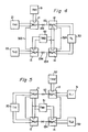
- the heat pump system shown in Figure 4 is the same as that shown in Figure 2 except that in the first operating unit, a receptacle 11 is connected to a medium-temperature heat medium 51 at a temperature TM1 and a receptacle 12 is connected to a medium-temperature heat medium 52 at a temperature TM2, and that in a second operating unit, both receptacles 13 and 14 are connected to the medium-temperature heat medium 52 at a temperature TM2.
- the operation of the heat pump system shown in Figure 4 is described below with reference to the cycle diagram of Figure 3.
- the receptacle 11 When in the first operating unit, the receptacle 11 is connected to a high-temperature driving heat source 21 to heat M 1 H to a temperature TH1 and the receptacle 12 is connected to the medium-temperature heat medium 52 to maintain M 3 H at temperature TM2, M 1 H endothermically releases hydrogen (point A).
- the released hydrogen arrives at the receptacle 12 through a communication pipe 112 and is exothermically occluded by M 3 H (point B).
- the receptacle 13 is connected to the medium-temperature heat medium 52 at temperature TM2 and the receptacle 14 is connected to a low-temperature heat medium 30 at a temperature TL to permit M 3 H to release hydrogen endothermically (point C).
- the released hydrogen is led to the receptacle 13 by means of a communication pipe 134 and occluded exothermically by M Z H (point H).
- a cooling output can be obtained at the low-temperature heat medium (point C).
- the cooling output can, for example, be used for cooling.
- the heating output (point B) by hydrogen occlusion in M 3 H and the heating output (point H) by hydrogen occlusion in M 2 H can be utilized, for example, for supplying hot water, as required.
- the receptacle 11 After hydrogen transfer is completed in each of the operating units, the receptacle 11 is connected to the medium-temperature heat medium 51 at temperature TM1 and the receptacle 12, to the low-temperature heat medium 30.
- M 3H endothermically releases hydrogen (point C), and the released hydrogen is exothermically occluded by M 1 H (point D).
- a cooling output can be obtained at the low-temperature heat medium (point C).
- a heating output can be obtained at the medium-temperature heat medium (point D) by heat generation caused by hydrogen occlusion of M 1 H.
- the cooling output can be utilized, for example, for cooling, and the heating output can be used, for example, for heating or supplying of hot water.
- the receptacle 13 is connected to a second high-temperature driving heat source 22 to heat M 2 H to a temperature TH2 and the receptacle 14 is connected to the medium-temperature heat medium at temperature TM2, M Z H endothermically releases hydrogen (point E), and the released hydrogen is exothermically occluded by M 3 H (point B).
- heat generation induced by hydrogen occlusion in M 3 H can also be obtained as a heating output at the medium-temperature heat medium (point B).
- a cooling output and/or a heating output can be obtained by utilizing two high-temperature heat sources having different temperatures.
- M 2 H may be pre-heated to a temperature midway between the temperatures TH1 and TM2 by circulating a suitable heat medium between MIH at temperature THl and M 2 H at temperature TM2 through a line 313 when hydrogen transfer from M 1 H to M 3 H (A to B) in the first operating unit is over and hydrogen transfer from M 3 H to M 2 H (C to H) in the second operating unit is over.
- This preheating makes it possible to reduce heat supply from a driving heat source for heating M 2 H to temperature TH2 in the next step, and is advantageous to the economy of heat energy.
- a cooling output of about 10°C and a heating output of about 450C can be obtained. These outputs can be conveniently used for cooling and hot water supply.
- reaction receptacles 11 and 13 are connected to a single high-temperature driving heat source 20, a reaction receptacle 12, to a first low-temperature heat source 31 (for example, atmospheric air), and a reaction receptacle 14, to a second low-temperature heat source 32 (for example, solar heat) at a temperature TL2 (TL1 ⁇ TL2).
- the reaction receptacles 11, 13 and 14 are also connected to a first medium-temperature heat medium 51 at a temperature TM1, and the receptacle 12, to a second medium-temperature heat source 52 at temperature TM2 (TM1 > TM2).
- M 1 H having the lowest equilibrium dissociation pressure and M 3 H having a high equilibrium dissociation pressure constitute a first operating unit
- M 2 H having the second lowest equilibrium dissociation pressure and M 3 H having a high equilibrium dissociation pressure constitute a second operating unit
- a first operating unit performs a cycle A ⁇ B - C - D
- a second operating unit performs a cycle E - F G ⁇ H.
- M 1 H is heated by a high-temperature heat source at a temperature TH to effect hydrogen transfer from M 1 H to M 3 H, and heat generation (point B) at this time can be obtained as a heating output for heating and hot water supply.
- M 3 H which has thus occluded hydrogen is then connected to a low-temperature heat medium 31 at a temperature TL1, and meanwhile, M 1 H which has released hydrogen is connected to a medium-temperature heat medium 51 at a temperature TM1.
- a heating output (point D) obtained by hydrogen occlusion of M 1 H can be utilized for heating and hot water supply.
- M 2 H is heated by a high-temperature heat medium 20 at temperature TH to cause hydrogen transfer from M 2 H to M 3 H, and consequently, a heating output (point F) can be obtained.
- This heating output can be used for heating and hot water supply.
- M 3 H which has occluded hydrogen is then heated by a low-temperature heat source 32 at temperature TL2, for example solar heat, whereas M 2 H which has released hydrogen is cooled by a medium-temperature heat medium 51 to cause hydrogen transfer from M 3 H to M 2 H.
- a heating output (point H) can be obtained by hydrogen occlusion in M 2 H, and can be used for heating and hot water supply.
- one of the two low-temperature heat media having different temperatures is used to operate one of the two operating units.
- This embodiment is advantageous to the economy of heat energy since such an inexpensive heat energy as solar heat can be effectively utilized and heat can be pumped up from atmospheric air, too.
- hydrogen transfer from G to H fails if solar heat cannot be used.
- hydrogen transfer from G to H can be effected by giving heat at temperature TM2 from point B, which is of poor quality as a heating output, to M 3 H at point G.
- the first operating unit consisting of M 1 H and M 3 H performs a cycle A - B - C D, and is driven by the first medium-temperature heat media at temperature TM1 and the second medium-temperature heat medium at temperature TM2 to give a heat output (point A) at temperature TH.
- the second operating unit consisting of M 2 H and M 3 H performs a cycle E - F - D - H, and is driven by the first and second medium-temperature heat media kept at TM1 and TM2 respectively to give a heating output (E) at temperature TH.
- heating outputs at high temperatures can be obtained from points A and B by using two types of medium-temperature driving heat sources of low quality. It is also possible to take out a large amount of cooling output from a medium-temperature heat medium by utilizing a low-temperature heat medium such as liquefied natural gas.
- reaction receptacles 11, 12, 13 and 14 respectively contain M 3 H, M 1 H, M 3 H and M 2 H.
- the receptacle 11 is connected to a first high-temperature driving heat source 21 at temperature TH1 and a first medium-temperature heat medium 51 at a temperature TM1; the receptacle 12, to a low-temperature heat medium 30 at temperature TL and a second medium-temperature heat medium 52 at temperature TM2 (TM1 > TM2); the receptacle 13, to a second high-temperature heat source 22 at temperature TH2 (TH1 > TH2) and a second medium-temperature heat medium 52; and the receptacle 14, to a low-temperature heat medium 30 and a second medium-temperature heat medium 52.
- M 3 H having a low equilibrium dissociation pressure and M 1 H having the highest-equilibrium dissociation pressure constitute a first operating unit
- M 3 H and M 2 H having the second highest equilibrium dissociation pressure constitute a first operating unit
- the operation of the heat pump system shown in Figure 8 will be described with reference to the cycle diagram of Figure 9.
- the first operating unit consisting of M1H and M3H performs a cycle A - B - C - D by the first driving heat source 21 at temperature TH1 to give a cooling output (point C) at temperature TL and a heating output (point D) at temperature TM1.
- a heating output TM2 incident to hydrogen transfer from M 3 H to M 1 H can also be utilized, as necessary, but may be released into the outer atmosphere.
- the second operating unit consisting of M 3 H and M 2 H performs a cycle E - F - G - H by means of the second driving heat source 22 at temperature TH2 to give a cooling output at temperature TL.
- a heating output (at points F and H) at temperature TM2 obtained by hydrogen occlusion of M 3 H and M 2 H can similarly be utilized, as required, but may be released out of the system.
- the cooling output at temperature TL can be utilized for cooling
- the heating output at temperature TM1 (and temperature TM2) can be utilized for heating and hot water supply.
- the heat pump system of this invention comprising a first operating unit consisting of M 3 H and M I H and a second operating unit consisting of M 3 H and M 2 H may be operated by using two types of low temperature driving heat sources in accordance with the cycle shown in Figure 10.
- the first operating unit performs a cycle A - B - C D.
- M 3 H is heated by the high-temperature driving heat source (point A) at temperature TH and a first low-temperature heat source (point C) to give a heating output at the medium-temperature heat media (points D and B).
- the second operating unit performs a cycle A - F - G - H.
- M 3 H is heated by the high-temperature driving heat source (point A) and a second low-temperature heat medium (point G) at a temperature TL2 to give a heating output at the medium-temperature heat media (points H and F).
- the heating out- outs so obtained can be utilized for heating and/or hot water supply.
- the heat pump system of this invention comprising a first operating unit consisting of M 3 H and M 1 H and a second operating unit consisting of M 3 H and M 2 H may be operated in accordance with the anticlockwise cycle shown in Figure 11.
- M l H When subsequently in the first operating unit, M l H is connected to the low-temperature heat medium and M 3 H is connected to a medium-temperature heat medium at temperature TM2, M 3 H releases hydrogen endothermically (point B), and the released hydrogen is occluded by M 1 H (point C).
- M 2 H when in the second operating unit, M 2 H is connected to the second medium-temperature heat medium at TM2 and M 3 H to the high-temperature heat medium, M 2 H endothermicallv releases hydrogen (point H), and the released hydrogen is exothermically occluded by M 3 H (point A).
- a heating output can be obtained by hydrogen occlusion of M 3 H.
- a new cycle is started.
- a heating output at a higher temperature can be obtained by utilizing two types of medium-temperature heat source having different temperatures.
- reaction receptacles 11, 12, 13 and 14 respectively contain metal hydrides M 1 H, M 3 H, M 2 H and M 4 H.
- M 1H has the lowest equilibrium dissociation pressure
- M 2 H has the second lowest equilibrium dissociation pressure
- M 3 H has the highest equilibrium dissociation pressure
- M 4 H has the second highest equilibrium dissociation pressure.
- the receptacle 11 is connected to a first high-temperature driving heat source 21 at temperature TH1 and a first medium-temperature heat medium 51 at temperature TM1
- the receptacle 12 is connected to a low-temperature heat medium 30 at temperature TL and a second medium-temperature heat medium 52 at temperature TM2 (TM1 > TM2).
- the receptacle 13 is connected to a second high-temperature driving heat source 22 at temperature TH2 (TH1 > TH2) and a second medium-temperature heat medium 52, and the receptacle 14 is connected to the low-temperature heat medium 30 and the second medium-temperature heat medium 52.
- M 1 H and M 3 H constitute a first operating unit
- M 2H and M 4 H a second operating unit.
- the heat pump system shown in Figure 12 is operated in accordance with the same cycle as shown in Figure 9 (i.e., the cycle shown by a solid line in Figure 13), and the outputs obtained are the same as in Figure 9.
- the metal hydride heat pump system of this invention may comprise three or more operating units. It is essential in this case that the equilibrium dissociation pressure characteristics of one or both of a first and a second metal hydride in one operating unit be different from the equilibrium dissociation pressure characteristics of one or both of a first and a second metal hydride in at least one other operating unit.
- the amount of metal hydrides in one unit may differ from that in the other unit.
- the amount of metal hydrides may differ wholly or partly from unit to unit.
- a receptacle 1 is comprises of an elongated copper pipe 2, an aluminum fin 3 having a radial cross section and extending axially through the inside of the copper pipe 2, and a porous Teflon (polytetrafluoroethylene) tube 4 extending axially through one space in the fin 3.
- the copper pipe 2, for example, has a diameter of 20 mm and a wall thickness of 1 mm
- the Teflon tube 4 has a diameter of 3 mm, a wall thickness of 0.5 mm and a pore diameter of 2 pm.
- a number of cuts each with a depth of 1 mm are provided in the aluminum fin at an interval of 50 mm along its length to permit flowing of hydrogen into and out of the chambers defined by the fin.
- a metal hydride is filled in each of chamber defined by the inner surface of the copper tube 2 and the fin 3.
- the receptacle 1 having the aforesaid structure is described in detail in Japanese Utility Model Application No. 101611/1981 by the present Applicant, and is preferred because the occlusion and releasing of hydrogen can be performed rapidly and has a light weight and a low heat capacity.
- the heat pump system shown in Figure 4 is constructed by using receptacles 11, 12, 13 and 14 having the structure shown in Figures 14a and 14b.
- LaNi 5 . 5 is used as M 1 H; LaNi 4.85 Al 0.15 , as M 2 H ; and LaNi 4.75 Al 0.25 , as M 3 H.
- An experiment is conducted by using this heat pump system with different amounts of the metal hydrides as shown in Table 1. The method of operating the heat pump in each experiment is described with reference to Figures 3 and 4.
- heat exchange is performed between M 3 H at the receptacle 12 and M 3 H at the receptacle 14 to pre-cool M 3 H (receptacle 12) to a temperature intermediate between TM2 and TL1.
- a cooling output TL and a hot water supply output TM1 are obtained by using two heat sources TH1 and TH2.
- the reference numeral 10 represents the heat pump system of this invention in simplified form.
- the heat pump 10 is connected thermally to a driving heat source 20 such as a burner, and M 1 H is heated to a temperature TH.
- a cooling output from M 2 H is given to a cooling indoor device 30 by suitable thermal connection. Water, for example, is used as a cooling medium.
- the cooling output of the heat pump 10 is accumulated in a cold accumulator tank 104 and may be taken out from it and fed to the cooling indoor device.
- M 3 H In the heat pump, M 3 H generates heat when M 1H is heated to temperature TH and by the difference in equilibrium dissociation pressure, hydrogen is occluded by M 3 H. On the other hand, heat is generated when M 1 H occludes hydrogen released at temperature TL from M 3 H.
- the heat pump in order to utilize the heat released from M 1 H and/or M 3 H upon hydrogen occlusion, the heat pump is connected thermally to a heat accumulator tank 50 such as a water tank.
- a heat medium is circulated between the heat pump 10 and the heat accumulator tank 50 through a line 107.
- the excess heat or discharged heat occurring when the driving heat source 20 drives the heat pump is obtained by thermal connection to the heat accumulator tank 50.
- Heat medium for driving the heat pump is a gas or liquid
- it is circulated through the driving heat source, the heat pump and the heat accumulator tank in this order through the line 106, and returned to the driving heat source.
- the heat medium lines 106 and 107 are opened or closed by a suitable control device such as an electromagnetic valve according to the operating cycle of the heat pump 10.
- a temperature sensor 108 is provided in the heat medium line 107 in order to sense the temperature of the heat medium in the line 107
- a temperature sensor 109 is disposed in the heat accumulator tank 50 in order to sense the temperature of the heat medium.
- the heat medium line 107 is connected not to the heat accumulator tank 50 but to a heat dissipator 111 for heat dissipation by a control valve 110 provided in the line 107.
- the heat dissipator is, for example, a cooler using water.
- a heating output and a cooling output can be obtained simultaneously by operating the heat pump without wasteful consumption of a heat energy. Consequently, the coefficient of performance of the entire system, which is defined by cooling and heating output based on the amount of energy used, is markedly increased over a conventional system in which water supply by gas combustion and cooling by electricity are performed independently from each other.
- Figure 16 shows another embodiment of the metal hydride heat pump system of the invention.
- Reaction receptacles 11 and 13 contain a first metal hydride M 1 H
- reaction receptacles 15 and 17 contain a first metal hydride M' 1 H different from M 1 H
- receptacles 12, 14, 16 and 18 contain a second metal hydride M 2 H.
- the receptacles 11 and 12 constitute a first operating unit; the receptacles 13 and 14, a second operating unit; the receptacles 15 and 16, a third operating unit; and the receptacles 17 and 18, a fourth operating unit.
- the receptacles 15 to 18 are disposed symmetrically with respect to the receptacles 11 to 14, and perform the same operation with a delay of a half cycle from the cycle performed by the receptacles 11 to 14.
- a high-temperature heat medium 21 at temperature T 1 is connected heat-exchangeably to the receptacle 11 through a pump 221, and a high-temperature heat medium 22 at temperature T'l is connected heat-exchangeably to the receptacle 15 by means of a pump 222.
- a medium-temperature heat medium (such as cooling water) 51 at temperature T 3 is connected heat-exchangeably to the receptacles 11, 13 and 14 by means of pumps 254 and 255.
- a low-temperature heat medium 30 at temperature T 4 is connected heat-exchangeably to the receptacles 12 and 14 by means of pumps 232 and 243.
- a heat exchanger 523 is provided to perform heat exchange between the receptacles 12 and 13.
- the heat exchanger 523 is, for example, a heat medium circulating pipe equipped with a pump 623.
- hydrogen flowing pipes 112 and 134 equipped respectively with control valves 212 and 234 are provided between the receptacles 11 and 12, and between the receptacles 13 and 14, respectively.
- the receptacles 15 to 18 are symmetrical to the receptacles 11 to 14, and are connected similarly to medium-temperature and low-temperature heat media except that the receptacle 15 is connected to the high-temperature heat medium 22.
- a heat exchanger 567 equipped with a pump 667 is provided between the receptacles 16 and 17, and hydrogen flow pipes 156 and 178 equipped respectively with control valves 256 and 278 are provided between the receptacles 15 and 16 and between the receptacles 17 and 18, respectively.
- heat medium circulating pipes having pumps 415, 426, 437 and 448 as heat exchangers 315, 326, 337 and 348 are disposed between the reaction receptacles 11 to 14 and the receptacles 16 to 18, respectively.
- Heat exchange between heating media and the receptacles, heat exchange between the receptacles, and opening and closing of the hydrogen flowing pipes are performed by controlling at different times pumps, control valves and switch valves (not shown) provided in the heat medium flow paths.
- MIH and M' 1 H are used as the first metal hydride in accordance with this invention.
- its operating cycle may be quite the same as in the case of using the same kind of metal hydride.
- Figure 17 shows a cycle of obtaining a cooling output and a heating output using LaNi 4.7 Al 0.3 as a first metal hydride M 1 H and LaNi 5 as a second metal hydride M 2 H
- Figure 18 shows a timing chart showing the operation of this device.
- a receptacle 15 is connected to a high-temperature heat medium T 1 as is a receptacle 11.
- receptacles 11 and 12 of a first operating unit are at points A and F, respectively and hydrogen transfer from M 2 H in the receptacle 12 [(M 2 H) 1 1 to M 1 H of the receptacle 11 [(M 1 H) 1 ] is over; and receptacles 13 and 14 in a second operating unit are at points A and F, respectively, and hydrogen transfer from M 2 H in the receptacle 14 [(M 2 H) 2 ] to M 1 H of the receptacle 13 [(M 1 H) 2 ] is over.
- the following states exist at the starting point of the cycle.
- the receptacles 15 to 16 are at points C and D, and hydrogen transfer from M 1 H of the receptacle 15 C(M' 1 H) 3 ) to M 2 H in the receptacle 16 C(M 2 H) 3 ] is over; and in a fourth operating unit, the receptacles 17 and 18 are at points B and E respectively, the receptacle 17 has released hydrogen by being given heat from the receptacle 16 through a heat exchanger 567, and the receptacle 18 has occluded the released hydrogen.
- the operating positions of these receptacles are shown in Figures 17 and 18.
- Step 1 in the cycle is heat exchange between the receptacles arranged in symmetry. Heat exchange is performed between the receptacles 11 and 15, between the receptacles 12 and 16, between the receptacles 13 and 17 and between the receptacles 14 and 18 through heat exchangers 315, 326, 337 and 348, respectively to reduce the amount of heat or cold required for heating or cooling the respective receptacles in the next step.
- the positions of the respective receptacles on the cycle diagram at the end of this heat-exchanging step are shown at the righthand end of the column of step 1.
- Step 2 is temperature setting in which the receptacles 11, 15 and 17 after the end of heat exchanging are heated or cooled to predetermined temperatures by heat exchange with heat media.
- the receptacle 11 is heated to point C by high-temperature heat medium 21, and the receptacles 15 and 17 are cooled to point A by the medium-temperature heat medium 51.
- the other receptacles are left intact without heating or cooling.
- control valves 212, 234, 256 and 278 are opened to keep all hydrogen flowing pipes open and to permit hydrogen transfer from the receptacle 11 to the receptacle 12, from the receptacle 13 to the receptacle 14, from the receptacle 16 to the receptacle 15, and from the receptacle 18 to the receptacle 17.
- the hydrogen transfer from the receptacle 11 to the receptacle 12 corresponds to hydrogen transfer from point C to point D in the cycle diagram.
- hydrogen transfer from 13 to 14, from 16 to 15 and from 18 to 17 correspond to hydrogen transfer from B to E, from F to A, and from F to A, respectively.
- Heat generated by the receptacle 12 is given to the receptacle 13 by means of a heat exchanger 523.
- the receptacles 16 and 18 take away heat from the low-temperature heat source 30 incident to releasing of hydrogen from M 2 H, and the receptacles 14. 15 and 17 give heat to the medium-temperature heat medium 51 incident to occlusion of hydrogen. Accordingly, a cooling function can be obtained by using the high-temperature heat media 21 and 22 as a driving heat source and cooling water as the medium-temperature heat medium 51, and connecting the low-temperature heat medium 30 to a cooling load.
- a heating function can be obtained by using the high-temperature media 21 and 22 and low-temperature heat medium 30 as a driving heat source, and connecting the medium-temperature heat medium to a heating load.
- a half cycle ends.
- the receptacles 11 to 18 are at points C, D, B, E, A, F, A and F, respectively.
- the positions of the receptacles 11 to 14 correspond to the positions of the receptacles 15 to 18 at the start of step 1.
- the receptacles 11 to 14 take over the operations of the receptacles 15 to 18 in the first half cycle, or vice versa. Hence, a description of the latter half cycle is omitted.
- the coefficient of performance of the above heat pump systems will be determined on the basis of the above operations. To simplify calculations, let us assume that the amount of hydrogen transferred between the receptacles 11 and 12 and between the receptacles 15 and 16 is 1 mole, and the heats of reaction of M 1 H and M 2 H per mole of hydrogen reacted are AH 1 and ⁇ H 2 , respectively, and that the heat capacity for each of the metal hydrides and the receptacles per mole of hydrogen reacted is J.
- the heat exchange efficiency, n, in heat exchanging between the receptacles is defined by the following equation.
- Th is the temperature of a receptacle at a high temperature
- Tc is the temperature of a receptacle at a low temperature
- T is a temperature corresponding to (Th+Tc)/2
- Th' is the temperature of the receptacle at the high temperature after heat exchanging
- Tc' is the temperature of the receptacle at the low temperature after heat exchanging.
- Tm in the above equation means the temperature of each of the receptacles when heat exchange between the receptacles is carried out completely.
- the temperature of the reaction vessel at the high temperature after the heat exchanging is given by the following equation and the temperature of the receptacle at the low temperature after heat exchanging is given by the following equation
- temperatures at points C, D, B, A(E) and F are T 1 , T 2 h, T 2 l, T 3 and T 4 respectively
- the amount of heat required to heat the receptacle 11 from point G to C in step 2 is J(T 1 - T 3 )(1 - ⁇ /2)
- the amount of heat required to transfer hydrogen from (M 1 H) 1 to ( M 2 H ) 1 in step 3 is ⁇ H 1 .
- (M 2 H) 1 generates heat in an amount of p H 2 incident to hydrogen occlusion, but heat in an amount of J(T 2 h - T 4 )(1 - ⁇ /2) is consumed from the generated heat in order to heat the receptacle 12 from point H to D.
- heat in an amount of ⁇ H 2 - J(T 2 h - T 4 )(1 - ⁇ /2) is given to the receptacle 13.
- the heat in this amount is used to transfer hydrogen from (M1H)2 to (M 2 H) 2 (from point B to E) excepting the heat consumed to heat the receptacle 13 from point I to B.
- x can be obtained from the following equation.
- the receptacle 16 takes away heat in an amount of ⁇ H 2 - J(T 2 h - T 4 )(1 - ⁇ /2) from the low-temperature heat medium 30 incident to hydrogen transfer from (M 2 H ) 2 to (M 1 H) 2 (from point F to A), and the receptacle 18 likewise take away heat in an amount of
- the first half of the cycle is thus completed.
- the amount of heat fed into the heat pump system in order to drive the high-temperature heat medium 21 is given by the following formula.
- the amount of heat gained from the low-temperature heat medium 30 is given by the following formula.
- the amount of heat which the heat pump system has released into the medium-temperature heat medium 51 is given by the following formula.
- COPc in a conventional apparatus will be determined.
- the conventional apparatus exhibits only the behavior of the cycle C - E - F - A or B ⁇ E - F - A in Figure 17, and heat transfer between the receptacles 12 and 13 or the receptacles 16 and 17 as in the apparatus shown in Figure 16 does not occur.
- FIG 20 shows still another embodiment of the metal hydride heat pump system of this invention.
- a receptacle 11 contains a first metal hydride M 1 H; a receptacle 13, a first metal hydride M' 1 H which differ from M 1 H; and receptacles 12 and 14, a second metal hydride M 2 H.
- the receptacles 11 and 12 constitute a first operatinq unit, and the receptacles 13 and 14, a second operatinq unit.
- a high-temperature heat medium 21 at temperature T 1 is connected heat-exchangeably to the receptacle 11 by means of a pump 221.
- a high-temperature heat medium 22 at temperature T'l is connected heat-exchangeably to the receptacle 13 by means of a pump 222.
- a medium-temperature heat medium 51 at a temperature T 3 is connected heat-exchangeably to the receptacles 11, 12, 13 and 14 through pumps 254 and 255.
- a low-temperature heat medium 30 at temperature T 4 is connected to the receptacles 12 and 14 by means of a pump 231.
- a heat accumulator tank 250 is provided among the receptacles 11, 12, 13 and 14 and connected to these receptacles by heat exchangers 351, 352, 353 and 354, respectively.
- the heat accumulator tank 250 is adapted to receive heat generated by the receptacles 12 and 14, and give the accumulated heat to the receptacles 11 and 13, as required.
- the heat-exchangers 351, 352, 353 and 354 are provided respectively with pumps 451, 452, 453 and 454. Hydrogen flowing pipts 112 and 134 equipped respectively with control valves 212 and 234 are disposed between the receptacles 11 and 12 and between the receptacles 13 and 14.
- Heat exchangers 313 and 324 equipped respectively with pumps 413 and 424 are provided between the receptacles 11 and 13 and between the receptacles 12 and 14, respectively. Switch valves, etc. to be provided in the heat medium flow passages are omitted.
- the above heat pump system uses a first metal hydride M 1 H of the same kind in the receptacles 11 and 13, and can therefore be operated according to the same cycle as in a heat pump using one type of a high-temperature heat medium 21.
- control valves 212 and 234 are closed and heat-exchange is effected between the receptacles 11 and 13 and between the receptacles 12 and 14 by means of the heat exchangers 313 and 324, the receptacles 11, 12, 13 and 14 reach points K, L, M and N. Then, the receptacle 11 is heated to point C by the high-temperature heat medium 21, and the receptacle 13 is cooled to point A by the medium-temperature heat medium 51.
- the control valves 212 and 234 are opened to perform hydrogen transfer from MIH to M 2 H (between points C and D) in the receptacles 11 and 12.
- a heating function can be obtained by using the high-temperature heat medium 21 and the low-temperature heat medium 30 as driving heat sources and connecting the medium-temperature heat medium 51 to a heating load.
- the receptacles 11, 12, 13 and 14 move as follows through heat exchanging and heating or cooling, and proceed to the next step.
- Heat generated from (M 2 H) 1 or (M 2 H) 2 occluding hydrogen at point D is accumulated in the heat accumulator tank 250. As required (for example, one in each cycle), it is taken out through the heat exchanger 351 or 353, and given to M 1 H in the receptacle 11 [(M 1 H) 1 ] or M 1 H in the receptacle 13 [(M' 1 H) 2 ] which has fully occluded hydrogen. (M 1 H) 1 or (M'1H) 2 releases hydrogen at point B, and the released hydrogen is occluded by (M 2 H) 1 or (M 2 H) 2 which is cooled by the medium-temperature heat medium 51. At this time, (M 2 H) 1 or (M 2 H) 2 is located at point E.
- the receptacle 11 or 13 reaches point B through the route A - K - B. Movement from A to K is effected by heat exchange with the receptacle 13 or 11. Except the heat for heating from K to B, the given heat is used for hydrogen releasing.
- the receptacle 12 or 14 located at point E moves through E - H - F, and movement from E to H is effected by heat exchange with the receptacle 14 or 12.
- To release hydrogen at point F the receptacle 12 or 14 is cooled by an amount corresponding to H - F.
- the receptacle 13 or 11 at point A moves through A ⁇ I - C
- the receptacle 14 or 12 at point F moves through F - J - D. Then, the next step (A - C - D - F) will begin.
Landscapes
- Engineering & Computer Science (AREA)
- Physics & Mathematics (AREA)
- Mechanical Engineering (AREA)
- Thermal Sciences (AREA)
- General Engineering & Computer Science (AREA)
- Sorption Type Refrigeration Machines (AREA)
Abstract
Description
- This invention relates to a metal hydride heat pump system, and particularly to a metal hydride heat pump system having an increased coefficient of performance and exhibiting an excellent economy of thermal energy.
- It is known that a certain metal or alloy exothermically occludes hydrogen to form a metal hydride and the metal hydride reversibly releases hydrogen. In recent years, various metal hydride devices such as heat pumps which utilize this property of metal hydrides have been proposed. Such a heat pump can be constructed by filling a first metal hydride (MIH) and a second metal hydride (M2H), which have different equilibrium dissociation pressures at the same temperature, into closed receptacles capable of effecting heat exchange with a heat medium, and connecting these receptacles so as to permit transfer of hydrogen therebetween and to provide an operating unit.
- The operation of such a metal hydride heat pump is described with reference to Figure 1 which is a cycle diagram. It is known that as shown in Figure 1 the logarithm (in P) of the equilibrium dissociation pressure of a metal hydride decreases substantially linearly as the reciprocal (1/T) of the absolute temperature increases. With reference to Figure 1, it is assumed that initially M1H is in a state of fully occluding hydrogen (point D) and M2H is in a state of having fully released hydrogen (point C). When M2H having a low equilibrium dissociation pressure in an operating temperature range is heated by a high-temperature driving heat source at temperature TH and M2H having a higher equilibrium dissociation pressure is connected to a medium-temperature heat medium at temperature TM which is, for example, the atmospheric air, M1H releases hydrogen endothermically (point A) and M2H occludes this hydrogen exothermically (point B). When after the transfer of hydrogen is completed, M1H is connected to a medium-temperature heat medium and M2H is connected to a low-temperature heat medium at temperature TL for cooling load such as cold water, M2H endothermically released hydrogen (point C), and MIH exothermically occludes this hydrogen (point D). Thus, a cooling output can be obtained at the low-temperature heat medium (point C). By again connecting M 1H to the high-temperature driving heat source and M2H, to the medium-temperature heat medium, a new cycle is started, If the same operating unit as above is provided and the same cycle as above is performed in this unit with a delay of a half cycle, a cooling output accompanying the releasing of hydrogen from M2H can be obtained alternately from these operating units. The output obtained can be utilized, for example, for cooling.
- Various kinds of such metal hydride heat pumps have been proposed recently, but are still desired to be improved because they all have a low heat efficiency.
- The present invention provides a metal hydride heat pump system comprising a plurality of operating units, each operating units comprising a combination of a first metal hydride having a lower equilibrium dissociation pressure at an operating temperature and a second metal hydride having a higher equilibrium dissociation pressure at the operating temperature in such a manner that hydrogen can flow freely between the two metal hydrides, wherein the equilibrium dissociation pressure characteristics of one or both of the first and second metal hydrides in a given operating unit differ from those of one or both of the first and second metal hydrides in at least one other operating unit.
- Now, let us assume that, for example, the metal hydride heat pump consists of two operating units, and a first and a second metal hydride in a first operating unit are designated respectively as (M1H)1 and (M2H)1, and a first and a second metal hydride in a second operating unit are designated respectively as (M1H)2 and (M2H)2. Then, the present invention includes the following instances: (1) where the equilibrium dissociation pressure characte- ristics of (M lH)1 and (M1H)2 differ from each other and (M 2H)1 and (M2H)2 have the same equilibrium dissociation pressure characteristics; (2) where (M1H)1 and (M1H)2 have the same equilibrium dissociation pressure characteristics and (M2H)1 and (M2H)2 have different equilibrium dissociation pressure characteristics; and (3) where (M1H)1 and (M1H)2 have different equilibrium dissociation pressure characteristics and tM2H)1 and (M2H)2 also have different dissociation pressure characteristics.
- By providing differences in the equilibrium dissociation pressure characteristics of one or both of the first and second metal hydrides between different operating units, a plurality of heat sources at different temperatures can be utilized simultaneously as driving heat sources, and there can be obtained a metal hydride heat pump which exhibits excellent economy in the utilization of heat sources and has an increased coefficient of performance.
- In the present invention, it is also possible to use different amounts of metal hydrides for the individual operating units in addition to the above requirement that the equilibrium dissociation pressure characteristics of one or both of the first and second metal hydrides in one operating unit differ from those of one or both of the first and second metal hydrides in another operating unit. This construction brings about the advantage that driving heat sources can be utilized efficiently and outputs can be increased by designing the operating units according to the amounts of driving heat sources at different temperatures. Furthermore, the coefficient of performance can be increased by using metal hydrides in a larger amount in an operating unit capable of giving both a cooling and a heating output than in another operating unit.
- In the heat pump system of this invention, each of the operating units is operated by a cycle which comprises releasing hydrogen from the first metal hydride by a driving heat source in a high-temperature range, causing the released hydrogen to be exothermically occluded by the second metal hydride in a medium-temperature range, then endothermically releasing hydrogen from the second metal hydride in a low-temperature range, and causing the released hydrogen to be exothermically occluded by the first metal hydride in a medium-temperature range. By this cycle, the heat absorption of the second metal hydride in the low-temperature range is obtained as a cooling output. At the same time, the generation of heat of the first metal hydride and/or the second metal hydride in the medium-temperature range may be obtained as a heating output. Preferably, heat accumulator means may be provided in order to utilize the generation of heat by the first metal hydride and/or the second metal hydride in the medium-temperature range as a heating output.
- By this procedure, the cooling output obtained can be used for example for domestic cooling and the heating output, for domestic hot water supply.
- Furthermore, in the heat pump system of this invention, each of the operating units is operated in accordance with a cycle comprising releasing hydrogen endothermically from the first metal hydride, causing the released hydrogen to be exothermically occluded by the second metal hydride, releasing hydrogen endothermically from the second metal hydride and causing the released hydrogen to be exothermically occluded by the first metal hydride. As a result, heat generation accompanying occlusion of hydrogen by the metal hydride is obtained as a heating output, and heat absorption accompanying hydrogen releasing from the metal hydrides, as a cooling output. In this cycle, heat generated by the hydrogen occlusion of the second metal hydride in one operating unit may be given to the first metal hydride in the same operating unit or in another operating unit, thereby effecting transfer of hydrogen from the first metal hydride to the second metal hydride. As a result, a driving heat energy required for hydrogen transfer can be reduced. In other words, a large amount of hydrogen can be transferred by a small amount of driving heat energy, and the coefficient of performance of the heat pump system increases further.
- The heat generated by the occlusion of hydrogen by the second metal hydride may be directly given to the first metal hydride in the other operating unit; alternatively, it may be stored in an accumulator means and given to the first metal hydride whenever required.
- The metal hydride heat pump system of this invention will be described below in detail with reference to the accompanying drawings showing specific embodiment of the invention.
- Figure 2 is a circuit diagram showing one example of the heat pump system of this invention;
- Figure 3 is a cycle diagram showing the operation of the heat pump system of the invention shown in Figure 4;
- Figure 4 is a circuit diagram of another example of the heat pump system of this invention;
- Figure 5 is a circuit diagram showing another example of the heat pump system of the invention;
- Figure 6 is a cycle diagram showing the heating and hot water supplying operations of the heat pump system shown of the invention shown in Figure 5;
- Figure 7 is a cycle diagram showing the anticlockwise operation of the heat pump system shown in Figure 5;
- Figure 8 is a circuit diagram showing another example of the heat pump system of the invention;
- Figure 9 is a cycle diagram showing the operation of the heat pump system shown in Figure 8;
- Figure 10 is a cycle diagram showing the operation of the heat pump system of Figure 8 using two types of low-temperature driving heat sources;
- Figure 11 is a cycle diagram showing the anticlockwise operation of the heat pump system shown in Figure 8;
- Figure 12 is a circuit diagram showing another example of the heat pump system of this invention;
- Figure 13 is a cycle diagram showing the operation of the heat pump system shown in Figure 12;
- Figure 14 shows one example of a reaction receptacle used in the heat pump system of this invention, Figure 14a being its front sectional view, and Figure 14b being a sectional view taken along line A-A' of Figure 14a;
- Figure 15 is a block diagram showing another example of the heat pump system of the invention;
- Figure 16 is a circuit diagram showing one example of the heat pump system of the invention;
- Figure 17 is a cycle diagram showing the operation of the heat pump system in Figure 16 when one kind of first metal hydride is used;
- Figure 18 is a timing chart of the operation of the heat pump system shown in the cycle diagram of Figure 17;
- Figure 19 is a graph showing the heat-exchanging efficiency (n) versus the coefficient of performance in the operation of the heat pump system shown in Figure 17 and in the operation of a conventional heat pump; and
- Figure 20 is a circuit diagram showing still another embodiment of the heat pump system of the invention.
- Figure 2 shows an example of the heat pump system of this invention, in which three metal hydrides, M1H, M2H and M3H having different equilibrium dissociation pressures in an operating temperature range are used. M1H having the lowest equilibrium dissociation pressure and M2H having the second lower equilibrium dissociation pressure are filled respectively in closed
receptacles receptacles receptacles pipe 112 so as to permit transfer of hydrogen therebetween, and thus to provide a first operating unit. Similarly, thereceptacles pipe 134 to provide a second operating unit.Control valves communication pipes - The
receptacle 11 is connected, heat-exchangeably and switchably, to a firstdriving heat source 21 at a high temperature TH1 and a medium-temperature heat medium 50 at a temperature TM throughlines receptacle 13 is connected, heat exchangeably and switchably, to a second drivingheat source 22 at a high temperature TH2 (< THl) and the medium-temperature heat medium 50 throughlines receptacle 12 containing M3H having a high equilibrium dissociation pressure is connected, heat-exchangeably and switchably, to a low-temperature heat medium 30 at a temperature TL and the medium-temperature heat medium 50 bylines receptacle 14 containing M3H in the second operating unit is connected, heat-exchangeably and switchably, to the low-temperature heat medium 30 and the medium-temperature heat medium 50 bylines - Switching of each receptacle to the heat sources or the heat media is effected by a control valve such as an electromagnetic valve (not shown).
- The heat pump system shown in Figure 4 is the same as that shown in Figure 2 except that in the first operating unit, a
receptacle 11 is connected to a medium-temperature heat medium 51 at a temperature TM1 and areceptacle 12 is connected to a medium-temperature heat medium 52 at a temperature TM2, and that in a second operating unit, bothreceptacles temperature heat medium 52 at a temperature TM2. The operation of the heat pump system shown in Figure 4 is described below with reference to the cycle diagram of Figure 3. - When in the first operating unit, the
receptacle 11 is connected to a high-temperaturedriving heat source 21 to heat M1H to a temperature TH1 and thereceptacle 12 is connected to the medium-temperature heat medium 52 to maintain M3H at temperature TM2, M1H endothermically releases hydrogen (point A). The released hydrogen arrives at thereceptacle 12 through acommunication pipe 112 and is exothermically occluded by M3H (point B). At the same time, in the second operating unit, thereceptacle 13 is connected to the medium-temperature heat medium 52 at temperature TM2 and thereceptacle 14 is connected to a low-temperature heat medium 30 at a temperature TL to permit M3H to release hydrogen endothermically (point C). The released hydrogen is led to thereceptacle 13 by means of acommunication pipe 134 and occluded exothermically by MZH (point H). As a result, a cooling output can be obtained at the low-temperature heat medium (point C). The cooling output can, for example, be used for cooling. The heating output (point B) by hydrogen occlusion in M3H and the heating output (point H) by hydrogen occlusion in M2H can be utilized, for example, for supplying hot water, as required. - After hydrogen transfer is completed in each of the operating units, the
receptacle 11 is connected to the medium-temperature heat medium 51 at temperature TM1 and thereceptacle 12, to the low-temperature heat medium 30. As a result, by the difference in equilibrium dissociation pressure between M1H and M3H within the receptacles, M 3H endothermically releases hydrogen (point C), and the released hydrogen is exothermically occluded by M1H (point D). Accordingly, by heat absorption induced by hydrogen releasing of M3H, a cooling output can be obtained at the low-temperature heat medium (point C). Furthermore, a heating output can be obtained at the medium-temperature heat medium (point D) by heat generation caused by hydrogen occlusion of M1H. The cooling output can be utilized, for example, for cooling, and the heating output can be used, for example, for heating or supplying of hot water. - When at the same time, the
receptacle 13 is connected to a second high-temperaturedriving heat source 22 to heat M2H to a temperature TH2 and thereceptacle 14 is connected to the medium-temperature heat medium at temperature TM2, MZH endothermically releases hydrogen (point E), and the released hydrogen is exothermically occluded by M3H (point B). If desired, heat generation induced by hydrogen occlusion in M3H can also be obtained as a heating output at the medium-temperature heat medium (point B). - In this way, the clockwise cycle as shown in Figure 3 is completed. If the receptacles are then connected to the initial heat sources or heat media, a new cycle is started again.
- Thus, by the heat pump system of the invention, a cooling output and/or a heating output can be obtained by utilizing two high-temperature heat sources having different temperatures.
- In the embodiment shown in Figures 3 and 4, M2H may be pre-heated to a temperature midway between the temperatures TH1 and TM2 by circulating a suitable heat medium between MIH at temperature THl and M2H at temperature TM2 through a
line 313 when hydrogen transfer from M1H to M3H (A to B) in the first operating unit is over and hydrogen transfer from M3H to M2H (C to H) in the second operating unit is over. This preheating makes it possible to reduce heat supply from a driving heat source for heating M2H to temperature TH2 in the next step, and is advantageous to the economy of heat energy. Likewise, it is advantageous to the economy of heat energy to pre-heat or pre-cool M3H in thereceptacles line 324. - It is also advantageous to pre-heat or pre-cool metal hydrides by performing heat exchange between M2H at temperature TH2 and M1H at temperature TM1 and also between M3H at temperature TM2 and M3H at temperature TL when hydrogen transfer from M3H to M1H (C to D) in the first operating unit is over and hydrogen transfer from M2H to M3H in the second operating unit is over (E to B).
- If in the temperature cycle described above LaNi4.75Al0.25, LaNi4.85Al0.15 and LaNi 5.4 are used respectively as M1H, M2H and M3H, the temperatures of the heat media and heat sources can be prescribed roughly as follows:
-
- TH1 = 100°C (first high-temperature driving heat source)
- TH2 = 80°C (second high-temperature driving heat source)
- Output
- TL1 = 10°C (cooling output)
- TMl = 45°C (heating output)
- TM2 = 300C (atmospheric temperature)
- Accordingly, a cooling output of about 10°C and a heating output of about 450C can be obtained. These outputs can be conveniently used for cooling and hot water supply.
- In the heat pump system shown in Figure 5,
reaction receptacles driving heat source 20, areaction receptacle 12, to a first low-temperature heat source 31 (for example, atmospheric air), and areaction receptacle 14, to a second low-temperature heat source 32 (for example, solar heat) at a temperature TL2 (TL1 < TL2). The reaction receptacles 11, 13 and 14 are also connected to a first medium-temperature heat medium 51 at a temperature TM1, and thereceptacle 12, to a second medium-temperature heat source 52 at temperature TM2 (TM1 > TM2). As in the apparatus shown in Figure 2, M1H having the lowest equilibrium dissociation pressure and M3H having a high equilibrium dissociation pressure constitute a first operating unit, and M2H having the second lowest equilibrium dissociation pressure and M3H having a high equilibrium dissociation pressure constitute a second operating unit. - The operation of the heat pump system shown in Figure 5 for heating and hot water supply will be described with reference to the cycle diagram shown in Figure 6.
- A first operating unit performs a cycle A → B - C - D, and a second operating unit performs a cycle E - F G → H. In the first operating unit, M1H is heated by a high-temperature heat source at a temperature TH to effect hydrogen transfer from M1H to M3H, and heat generation (point B) at this time can be obtained as a heating output for heating and hot water supply. M3H which has thus occluded hydrogen is then connected to a low-
temperature heat medium 31 at a temperature TL1, and meanwhile, M1H which has released hydrogen is connected to a medium-temperature heat medium 51 at a temperature TM1. Thus, hydrogen transfer from M3H to M1H occurs, and a heating output (point D) obtained by hydrogen occlusion of M1H can be utilized for heating and hot water supply. - In the second operating unit, M2H is heated by a high-
temperature heat medium 20 at temperature TH to cause hydrogen transfer from M2H to M3H, and consequently, a heating output (point F) can be obtained. This heating output can be used for heating and hot water supply. M3H which has occluded hydrogen is then heated by a low-temperature heat source 32 at temperature TL2, for example solar heat, whereas M2H which has released hydrogen is cooled by a medium-temperature heat medium 51 to cause hydrogen transfer from M3H to M2H. Thus, a heating output (point H) can be obtained by hydrogen occlusion in M2H, and can be used for heating and hot water supply. - If the same combination of La-Ni type metal hydrides as in the aforesaid apparatuses described with reference to Figures 3 and 4 is used, the temperatures of the heat sources and heat media in the embodiment shown in Figure 5 can be prescribed as follows:
-
- TH1 = 110°C (high-temperature heat source)
- TL2 = 30°C (solar heat)
- TL1 = 0°C (atmospheric air)
- Output
- TM1 = 50°C (heating and hot water supply)
- TM2 = 40°C (hot water supply)
- In the apparatus which is operated in accordance with the cycle diagram of Figure 6, one of the two low-temperature heat media having different temperatures is used to operate one of the two operating units. This embodiment is advantageous to the economy of heat energy since such an inexpensive heat energy as solar heat can be effectively utilized and heat can be pumped up from atmospheric air, too.
- In conventional apparatuses, hydrogen transfer from G to H fails if solar heat cannot be used. According to the apparatus of this invention, hydrogen transfer from G to H can be effected by giving heat at temperature TM2 from point B, which is of poor quality as a heating output, to M3H at point G.
- The operation of the heat pump system of this invention comprising a first operating unit consisting of M1H and M3H and a second operating unit consisting of M2H and M3H as shown in Figure 5 according to an anticlockwise cycle will be described with reference to the cycle diagram of Figure 7.
- The first operating unit consisting of M1H and M3H performs a cycle A - B - C D, and is driven by the first medium-temperature heat media at temperature TM1 and the second medium-temperature heat medium at temperature TM2 to give a heat output (point A) at temperature TH. On the other hand, the second operating unit consisting of M2H and M3H performs a cycle E - F - D - H, and is driven by the first and second medium-temperature heat media kept at TM1 and TM2 respectively to give a heating output (E) at temperature TH.
- According to this anticlockwise cycle, heating outputs at high temperatures can be obtained from points A and B by using two types of medium-temperature driving heat sources of low quality. It is also possible to take out a large amount of cooling output from a medium-temperature heat medium by utilizing a low-temperature heat medium such as liquefied natural gas.
- In the heat pump system shown in Figure 8,
reaction receptacles receptacle 11 is connected to a first high-temperaturedriving heat source 21 at temperature TH1 and a first medium-temperature heat medium 51 at a temperature TM1; thereceptacle 12, to a low-temperature heat medium 30 at temperature TL and a second medium-temperature heat medium 52 at temperature TM2 (TM1 > TM2); thereceptacle 13, to a second high-temperature heat source 22 at temperature TH2 (TH1 > TH2) and a second medium-temperature heat medium 52; and thereceptacle 14, to a low-temperature heat medium 30 and a second medium-temperature heat medium 52. M3H having a low equilibrium dissociation pressure and M1H having the highest-equilibrium dissociation pressure constitute a first operating unit, and M3H and M2H having the second highest equilibrium dissociation pressure constitute a second operating unit. - The operation of the heat pump system shown in Figure 8 will be described with reference to the cycle diagram of Figure 9. The first operating unit consisting of M1H and M3H performs a cycle A - B - C - D by the first
driving heat source 21 at temperature TH1 to give a cooling output (point C) at temperature TL and a heating output (point D) at temperature TM1. A heating output TM2 incident to hydrogen transfer from M3H to M1H can also be utilized, as necessary, but may be released into the outer atmosphere. The second operating unit consisting of M3H and M2H performs a cycle E - F - G - H by means of the seconddriving heat source 22 at temperature TH2 to give a cooling output at temperature TL. A heating output (at points F and H) at temperature TM2 obtained by hydrogen occlusion of M3H and M2H can similarly be utilized, as required, but may be released out of the system. In this manner, the cooling output at temperature TL can be utilized for cooling, and the heating output at temperature TM1 (and temperature TM2) can be utilized for heating and hot water supply. - The heat pump system of this invention comprising a first operating unit consisting of M3H and MIH and a second operating unit consisting of M3H and M2H may be operated by using two types of low temperature driving heat sources in accordance with the cycle shown in Figure 10.
- Referring to Figure 10, the first operating unit performs a cycle A - B - C D. M3H is heated by the high-temperature driving heat source (point A) at temperature TH and a first low-temperature heat source (point C) to give a heating output at the medium-temperature heat media (points D and B). On the other hand, the second operating unit performs a cycle A - F - G - H. M3H is heated by the high-temperature driving heat source (point A) and a second low-temperature heat medium (point G) at a temperature TL2 to give a heating output at the medium-temperature heat media (points H and F). The heating out- outs so obtained can be utilized for heating and/or hot water supply.
- In Figure 10, it is possible as in the case shown in Figure 6 to use solar heat at point G and pump up the heat of the atmospheric air at point C.
- The heat pump system of this invention comprising a first operating unit consisting of M3H and M1H and a second operating unit consisting of M3H and M2H may be operated in accordance with the anticlockwise cycle shown in Figure 11.
- Referring to Figure 11, when the
receptacle 12 is connected to a first medium-temperature driving heat source to heat MIH to temperature TM1 and thereceptacle 11 is connected to a high-temperature heat medium to maintain M3H at temperature TH, M1H endothermically releases hydrogen (point D), and the released hydrogen is exothermically occluded by M3H (point A). On the other hand, in the second operating unit, thereceptacle 14 is connected to a low-temperature heat medium at temperature TL, and thereceptacle 13 is connected to the medium-temperature heat medium. As a result, M3H endothermically releases hydrogen (point F), and the released hydrogen is exothermically occluded by M2H (point G). When subsequently in the first operating unit, MlH is connected to the low-temperature heat medium and M3H is connected to a medium-temperature heat medium at temperature TM2, M3H releases hydrogen endothermically (point B), and the released hydrogen is occluded by M1H (point C). On the other hand, when in the second operating unit, M2H is connected to the second medium-temperature heat medium at TM2 and M3H to the high-temperature heat medium, M2H endothermicallv releases hydrogen (point H), and the released hydrogen is exothermically occluded by M3H (point A). Hence, a heating output can be obtained by hydrogen occlusion of M3H. By connecting the receptacles to the initial heat sources or heat media upon the completion of the anticlockwise cycle, a new cycle is started. As stated above, a heating output at a higher temperature can be obtained by utilizing two types of medium-temperature heat source having different temperatures. - In this anticlockwise cycle, too, it is advantageous to pre-heat a metal hydride at a low temperature and pre-cool a metal hydride at a high temperature for the next step by performing heat exchange between a receptacle having a high temperature and a receptacle having a low temperature when hydrogen transfer between the receptacles is completed as described above.
- In the heat pump systems shown in Figure 12,
reaction receptacles receptacle 11 is connected to a first high-temperaturedriving heat source 21 at temperature TH1 and a first medium-temperature heat medium 51 at temperature TM1, and thereceptacle 12 is connected to a low-temperature heat medium 30 at temperature TL and a second medium-temperature heat medium 52 at temperature TM2 (TM1 > TM2). Thereceptacle 13 is connected to a second high-temperaturedriving heat source 22 at temperature TH2 (TH1 > TH2) and a second medium-temperature heat medium 52, and thereceptacle 14 is connected to the low-temperature heat medium 30 and the second medium-temperature heat medium 52. M1H and M3H constitute a first operating unit, and M 2H and M4H, a second operating unit. - The heat pump system shown in Figure 12 is operated in accordance with the same cycle as shown in Figure 9 (i.e., the cycle shown by a solid line in Figure 13), and the outputs obtained are the same as in Figure 9.
- It is also possible to operate the heat pump system comprising M1H, M2H, M3H and M4H according to a cycle involving hydrogen transfer from C' to D' shown by a broken arrow in Figure 13, and to obtain heating outputs having the same temperature TM2 from points B, F, H and D' by using four types of driving heat sources THl, TH2, TL and TL2.
- The embodiments so far described consist of two operating units, but the metal hydride heat pump system of this invention may comprise three or more operating units. It is essential in this case that the equilibrium dissociation pressure characteristics of one or both of a first and a second metal hydride in one operating unit be different from the equilibrium dissociation pressure characteristics of one or both of a first and a second metal hydride in at least one other operating unit.
- In the heat pump system of this invention comprising two operating units, the amount of metal hydrides in one unit may differ from that in the other unit. When three or more operating units are used, the amount of metal hydrides may differ wholly or partly from unit to unit.
- One example of the receptacle for filling a metal hydride in the heat pump system of this invention is shown in Figures 14a and 14b. A
receptacle 1 is comprises of anelongated copper pipe 2, analuminum fin 3 having a radial cross section and extending axially through the inside of thecopper pipe 2, and a porous Teflon (polytetrafluoroethylene)tube 4 extending axially through one space in thefin 3. Thecopper pipe 2, for example, has a diameter of 20 mm and a wall thickness of 1 mm, and theTeflon tube 4 has a diameter of 3 mm, a wall thickness of 0.5 mm and a pore diameter of 2 pm. A number of cuts each with a depth of 1 mm are provided in the aluminum fin at an interval of 50 mm along its length to permit flowing of hydrogen into and out of the chambers defined by the fin. A metal hydride is filled in each of chamber defined by the inner surface of thecopper tube 2 and thefin 3. Thereceptacle 1 having the aforesaid structure is described in detail in Japanese Utility Model Application No. 101611/1981 by the present Applicant, and is preferred because the occlusion and releasing of hydrogen can be performed rapidly and has a light weight and a low heat capacity. - Thirteen or seven metal hydride receptacle having a length of 1,000 mm are assembled, and connected to a
single flow passage 6. The assembly is set in ajacket 5. A heat medium is charged into thejacket 5 through aninlet opening 7 and discharged through anoutlet opening 8 to perform heat exchange of the metal hydrides in the receptacles. - The heat pump system shown in Figure 4 is constructed by using
receptacles - (1) A heat medium TH1 at 100°C is circulated to m1H (receptacle 11) (point A). Water TM2 at 30°C is circulated to M3H (receptacle 12) (point B). Upon opening of a
hydrogen valve 212, hydrogen moves from thereceptacle 11 to thereceptacle 12. - (1)' Water TM2 at 30°C is circulated to M2H (receptacle 13) (point H). Cold water TL in a
storage tank 30 is circulated to M3H (receptacle 14) (point G). Upon opening of a heat absorbinghydrogen valve 234, hydrogen moves from thereceptacle 14 to thereceptacle 13. Cold water obtained by heat absorption at point C is circulated to an indoor fan convector thereby to cool the room. - (2) After hydrogen transfer is substantially over (about 9 minutes later), the
hydrogen valves - Simultaneously, heat exchange is performed between M3H at the
receptacle 12 and M3H at thereceptacle 14 to pre-cool M3H (receptacle 12) to a temperature intermediate between TM2 and TL1. - (3) A heat medium is circulated from a hot water supply heat accumulator tank 51 (TM1) to M1H (receptacle 11) (point D). Cold water TL in the
storage tank 30 is circulated to M3H (receptacle 12) (point C). Upon opening of thevalve 212, hydrogen easily moves from thereceptacle 12 to thereceptacle 11. Warm water is heated to 45°C by heat generation at point D, and cold water is obtained by heat absorption at point C. - (3)' A heat medium from a heat source TH2 at 30°C is re-circulated to M2H (receptacle 13) (point E). Water TM2 at 30°C is circulated to M3H (receptacle 14) (point B). Upon opening of the
hydrogen valve 234, hydrogen easily moves from thereceptacle 13 to thereceptacle 14. - (4) After hydrogen transfer is substantially over, the
hydrogen valves receptacles 11 and 13) and between M3H and M3H (receptacles 12 and 14) to complete one cycle of cooling or hot water supply. - By successively repeating the above cycle, a cooling output TL and a hot water supply output TM1 are obtained by using two heat sources TH1 and TH2.
- The heat balance at this time is as shown in Table 1.

- The parenthesized figures in the column of the type of the metal hydride designate receptacles.
- It is seen from Table 1 that the COP (coefficient of performance) is higher in Nos. 2 and 3 than in No. 1.
- Now, the embodiment shown in Figure 15 will be described. The
reference numeral 10 represents the heat pump system of this invention in simplified form. Theheat pump 10 is connected thermally to a drivingheat source 20 such as a burner, and M1H is heated to a temperature TH. A cooling output from M2H is given to a coolingindoor device 30 by suitable thermal connection. Water, for example, is used as a cooling medium. As necessary, the cooling output of theheat pump 10 is accumulated in acold accumulator tank 104 and may be taken out from it and fed to the cooling indoor device. - In the heat pump, M3H generates heat when M 1H is heated to temperature TH and by the difference in equilibrium dissociation pressure, hydrogen is occluded by M3H. On the other hand, heat is generated when M1H occludes hydrogen released at temperature TL from M3H. In this example, in order to utilize the heat released from M 1H and/or M3H upon hydrogen occlusion, the heat pump is connected thermally to a
heat accumulator tank 50 such as a water tank. For example, a heat medium is circulated between theheat pump 10 and theheat accumulator tank 50 through aline 107. On the other hand, the excess heat or discharged heat occurring when the drivingheat source 20 drives the heat pump is obtained by thermal connection to theheat accumulator tank 50. Water so heated is utilized for hot water supply. When the heat medium for driving the heat pump is a gas or liquid, it is circulated through the driving heat source, the heat pump and the heat accumulator tank in this order through theline 106, and returned to the driving heat source. Theheat medium lines heat pump 10. - Preferably, a
temperature sensor 108 is provided in theheat medium line 107 in order to sense the temperature of the heat medium in theline 107, and atemperature sensor 109 is disposed in theheat accumulator tank 50 in order to sense the temperature of the heat medium. When the temperature of the heat medium in theheat accumulator tank 50 is higher than that of the heat medium in theline 107, theheat medium line 107 is connected not to theheat accumulator tank 50 but to a heat dissipator 111 for heat dissipation by acontrol valve 110 provided in theline 107. The heat dissipator is, for example, a cooler using water. - Thus, when it is desired, for example, to perform hot water supply and cooling in a home, a heating output and a cooling output can be obtained simultaneously by operating the heat pump without wasteful consumption of a heat energy. Consequently, the coefficient of performance of the entire system, which is defined by cooling and heating output based on the amount of energy used, is markedly increased over a conventional system in which water supply by gas combustion and cooling by electricity are performed independently from each other.
- Figure 16 shows another embodiment of the metal hydride heat pump system of the invention.
Reaction receptacles reaction receptacles receptacles - The
receptacles receptacles receptacles receptacles receptacles 15 to 18 are disposed symmetrically with respect to thereceptacles 11 to 14, and perform the same operation with a delay of a half cycle from the cycle performed by thereceptacles 11 to 14. - A high-
temperature heat medium 21 at temperature T1 is connected heat-exchangeably to thereceptacle 11 through apump 221, and a high-temperature heat medium 22 at temperature T'l is connected heat-exchangeably to thereceptacle 15 by means of apump 222. A medium-temperature heat medium (such as cooling water) 51 at temperature T3 is connected heat-exchangeably to thereceptacles pumps temperature heat medium 30 at temperature T4 is connected heat-exchangeably to thereceptacles pumps heat exchanger 523 is provided to perform heat exchange between thereceptacles heat exchanger 523 is, for example, a heat medium circulating pipe equipped with apump 623. To permit hydrogen transfer between MIH and M2H,hydrogen flowing pipes control valves receptacles receptacles - As stated hereinabove, the
receptacles 15 to 18 are symmetrical to thereceptacles 11 to 14, and are connected similarly to medium-temperature and low-temperature heat media except that thereceptacle 15 is connected to the high-temperature heat medium 22. Aheat exchanger 567 equipped with apump 667 is provided between thereceptacles hydrogen flow pipes control valves receptacles receptacles - Furthermore, in the apparatus of this invention shown in Figure 16, heat medium circulating
pipes having pumps heat exchangers receptacles 16 to 18, respectively. Heat exchange between heating media and the receptacles, heat exchange between the receptacles, and opening and closing of the hydrogen flowing pipes are performed by controlling at different times pumps, control valves and switch valves (not shown) provided in the heat medium flow paths. - In the heat pump system shown in Figure 16, MIH and M'1H are used as the first metal hydride in accordance with this invention. However, its operating cycle may be quite the same as in the case of using the same kind of metal hydride.
- Figure 17 shows a cycle of obtaining a cooling output and a heating output using LaNi4.7Al0.3 as a first metal hydride M1H and LaNi5 as a second metal hydride M2H, and Figure 18 shows a timing chart showing the operation of this device. A
receptacle 15 is connected to a high-temperature heat medium T1 as is areceptacle 11. At the starting point of the cycle,receptacles receptacles regards receptacles 15 to 18 which correspond to thereceptacles 11 to 14 and operate with a delay of a half cycle, the following states exist at the starting point of the cycle. In a third operating unit, thereceptacles 15 to 16 are at points C and D, and hydrogen transfer from M1H of the receptacle 15 C(M'1H)3) to M2H in the receptacle 16 C(M2H)3] is over; and in a fourth operating unit, thereceptacles receptacle 17 has released hydrogen by being given heat from thereceptacle 16 through aheat exchanger 567, and thereceptacle 18 has occluded the released hydrogen. The operating positions of these receptacles are shown in Figures 17 and 18. -
Step 1 in the cycle is heat exchange between the receptacles arranged in symmetry. Heat exchange is performed between thereceptacles receptacles receptacles receptacles heat exchangers step 1. -
Step 2 is temperature setting in which thereceptacles receptacle 11 is heated to point C by high-temperature heat medium 21, and thereceptacles temperature heat medium 51. The other receptacles are left intact without heating or cooling. - In
step 3,control valves receptacle 11 to thereceptacle 12, from thereceptacle 13 to thereceptacle 14, from thereceptacle 16 to thereceptacle 15, and from thereceptacle 18 to thereceptacle 17. The hydrogen transfer from thereceptacle 11 to thereceptacle 12 corresponds to hydrogen transfer from point C to point D in the cycle diagram. Likewise, hydrogen transfer from 13 to 14, from 16 to 15 and from 18 to 17 correspond to hydrogen transfer from B to E, from F to A, and from F to A, respectively. Heat generated by thereceptacle 12 is given to thereceptacle 13 by means of aheat exchanger 523. In this step, thereceptacles temperature heat source 30 incident to releasing of hydrogen from M2H, and thereceptacles 14. 15 and 17 give heat to the medium-temperature heat medium 51 incident to occlusion of hydrogen. Accordingly, a cooling function can be obtained by using the high-temperature heat media temperature heat medium 51, and connecting the low-temperature heat medium 30 to a cooling load. On the other hand, a heating function can be obtained by using the high-temperature media temperature heat medium 30 as a driving heat source, and connecting the medium-temperature heat medium to a heating load. Thus, instep 3, a half cycle ends. - At the end of
step 3, thereceptacles 11 to 18 are at points C, D, B, E, A, F, A and F, respectively. The positions of thereceptacles 11 to 14 correspond to the positions of thereceptacles 15 to 18 at the start ofstep 1. In the latter half cycle consisting ofsteps 4 to 6, therefore, thereceptacles 11 to 14 take over the operations of thereceptacles 15 to 18 in the first half cycle, or vice versa. Hence, a description of the latter half cycle is omitted. - The coefficient of performance of the above heat pump systems will be determined on the basis of the above operations. To simplify calculations, let us assume that the amount of hydrogen transferred between the
receptacles receptacles 
- Tm in the above equation means the temperature of each of the receptacles when heat exchange between the receptacles is carried out completely. By using the heat exchange efficiency n, the temperature of the reaction vessel at the high temperature after the heat exchanging is given by the following equation


- It is assumed that with reference to Figure 17, when heat exchange is performed between the receptacles at points C and A, their temperatures reach points M and G respectively; when heat exchange is performed between the receptacles at points D and F, their temperatures reach points N and H, respectively; when heat exchange is performed between the receptacles at points B and A, their temperatures reach points K and I; and when heat exchange is performed between the receptacles B and F, their temperatures reach points L and J, respectively.
- If in the cycle diagram temperatures at points C, D, B, A(E) and F are T1, T2h, T2ℓ, T3 and T4 respectively, the amount of heat required to heat the
receptacle 11 from point G to C instep 2 is J(T1 - T3)(1 - η/2), and the amount of heat required to transfer hydrogen from (M1H)1 to (M 2 H)1 instep 3 is ΔH1. At this time, (M2H)1 generates heat in an amount of pH2 incident to hydrogen occlusion, but heat in an amount of J(T2h - T4)(1 - η/2) is consumed from the generated heat in order to heat thereceptacle 12 from point H to D. Hence, heat in an amount of ΔH2 - J(T2h - T4)(1 - η/2) is given to thereceptacle 13. The heat in this amount is used to transfer hydrogen from (M1H)2 to (M2H)2 (from point B to E) excepting the heat consumed to heat thereceptacle 13 from point I to B. Let the amount of hydrogen thus transferred be x moles, the heat required to heat thereceptacle 13 from point I to B is xJ (T2ℓ - T3 )(1 - η/2), and the amount of heat used for hydrogen transfer is xΔH1, and therefore, the heat generated by (M2H)2 at point E is xΔH2. - x can be obtained from the following equation.

- In the meantime, the
receptacle 16 takes away heat in an amount of ΔH2 - J(T2h - T4)(1 - η/2) from the low-temperature heat medium 30 incident to hydrogen transfer from (M2 H)2 to (M1H)2 (from point F to A), and thereceptacle 18 likewise take away heat in an amount of
- The first half of the cycle is thus completed. The amount of heat fed into the heat pump system in order to drive the high-
temperature heat medium 21 is given by the following formula.
- The amount of heat gained from the low-
temperature heat medium 30 is given by the following formula.
- The amount of heat which the heat pump system has released into the medium-
temperature heat medium 51 is given by the following formula.
- Since the above formulae (1), (2) and (3) can similarly be obtained with respect to the latter half cycle, the coefficient of performance in obtaining a cooling output is given by


- Now, it is assumed that ΔH1 = 8.1 (kcal/mole H2) is obtained for LaNi4.7Al0.3 and ΔH2 = 7.4 (kcal/mole H2) is obtained for LaNi., an appropriated value, 0.04 kcal/mole H2 (°C), is selected as J (the process of calculation is omitted), and T1 = 140°C, T2h = 85°C, T2ℓ = 80°C, T3 = 40°C, and T4 =10°C. Variations of COPc against n are shown by a solid line in Figure 19.
- Now, COPc in a conventional apparatus will be determined. The conventional apparatus exhibits only the behavior of the cycle C - E - F - A or B → E - F - A in Figure 17, and heat transfer between the
receptacles receptacles - In cycle B - E - F - A in Figure 17, after heat exchange between the receptacles, J(T2ℓ - T3)(1 - η/2) for heating the
receptacle 11 from point I to B and heat in an amount of ΔH1 for releasing hydrogen are fed as inputs, and there is obtained a cooling output corresponding to the balance obtained by subtracting the amount of cold J(T3 - T4)(1 - η/2) for cooling thereceptacle 12 from point H to F after heat exchange between the receptacles from the heat AH2 of reaction in M2H. Hence, the COPc is given by the following equation.
- Variations of COPc against n are shown by broken line I in Figure 19. Since n is usually at least 0.5, the coefficient of performance increases in the heat pump system of this invention.
- If the cycle C, E, F and A in Figure 17 is considered as a cycle of the conventional apparatus, COPs is obtained by substituting T1 for T2ℓ in equation (6). Variations of COPc against n are shown by broken line II in Figure 19, and an increase in COPc will be easily understood from Figure 19.
- Figure 20 shows still another embodiment of the metal hydride heat pump system of this invention. A
receptacle 11 contains a first metal hydride M1H; areceptacle 13, a first metal hydride M'1H which differ from M1H; andreceptacles H. The receptacles receptacles temperature heat medium 21 at temperature T1 is connected heat-exchangeably to thereceptacle 11 by means of apump 221. A high-temperature heat medium 22 at temperature T'l is connected heat-exchangeably to thereceptacle 13 by means of apump 222. A medium-temperature heat medium 51 at a temperature T3 is connected heat-exchangeably to thereceptacles pumps temperature heat medium 30 at temperature T4 is connected to thereceptacles pump 231. - A
heat accumulator tank 250 is provided among thereceptacles heat exchangers heat accumulator tank 250 is adapted to receive heat generated by thereceptacles receptacles exchangers pumps control valves receptacles receptacles Heat exchangers pumps receptacles receptacles receptacles temperature heat medium 21. - The operations of obtaining a cooling output and a heating output by the apparatus of Figure 20 will be described by reference to Figure 17 with regard to the case where LaNi4.7Al0.3 is used as MIH and M1IH, and LaNi5 is used as M2H and the
receptacles temperature heat medium 21. Let us assume that at the starting point of the cycle, thereceptacles receptacles - If the
control valves receptacles receptacles heat exchangers receptacles receptacle 11 is heated to point C by the high-temperature heat medium 21, and thereceptacle 13 is cooled to point A by the medium-temperature heat medium 51. Thecontrol valves receptacles receptacles temperature heat medium 30 incident to the releasing of hydrogen from M2H in the receptacle 14 [(M2H)1]. At point D, heat T2 generated incident to hydrogen occlusion by M2H in the receptacle 12 [(M2H)2] is accumulated in theheat accumulator tank 250 by means of theheat exchanger 352. Accordingly, a cooling function is obtained by using the high-temperature heat medium 21 as a driving heat source and atmospheric air as the medium-temperature heat medium 51 and connecting the low-temperature heat medium 30 to a cooling load. On the other hand, a heating function can be obtained by using the high-temperature heat medium 21 and the low-temperature heat medium 30 as driving heat sources and connecting the medium-temperature heat medium 51 to a heating load. Thereceptacles - Receptacle 11: C - M - A
- Receptacle 12: D - N - F
- Receptacle 13: A - K - C
- Receptacle 14: F - L - D
- Heat generated from (M2H)1 or (M2H)2 occluding hydrogen at point D is accumulated in the
heat accumulator tank 250. As required (for example, one in each cycle), it is taken out through theheat exchanger temperature heat medium 51. At this time, (M2H)1 or (M2H)2 is located at point E. - The
receptacle receptacle receptacle receptacle receptacle receptacle receptacle - In this manner, a driving heat source from a high-temperature heat medium can be effectively utilized in a multiplicity of stages in the apparatus of Figure 20. Needless to say, the operation of obtaining a heating output is on the same principle, and its description is omitted herein.
Claims (14)
Applications Claiming Priority (4)
| Application Number | Priority Date | Filing Date | Title |
|---|---|---|---|
| JP120995/81 | 1981-07-31 | ||
| JP12099581A JPS5822854A (en) | 1981-07-31 | 1981-07-31 | Heat/cold heat acquisition method |
| JP5682182A JPS58173358A (en) | 1982-04-05 | 1982-04-05 | Metal hydride device |
| JP56821/82 | 1982-04-05 |
Publications (3)
| Publication Number | Publication Date |
|---|---|
| EP0071271A2 true EP0071271A2 (en) | 1983-02-09 |
| EP0071271A3 EP0071271A3 (en) | 1983-05-25 |
| EP0071271B1 EP0071271B1 (en) | 1988-01-07 |
Family
ID=26397813
Family Applications (1)
| Application Number | Title | Priority Date | Filing Date |
|---|---|---|---|
| EP82106871A Expired EP0071271B1 (en) | 1981-07-31 | 1982-07-29 | Metal hydride heat pump system |
Country Status (3)
| Country | Link |
|---|---|
| US (1) | US4523635A (en) |
| EP (1) | EP0071271B1 (en) |
| DE (1) | DE3277930D1 (en) |
Cited By (24)
| Publication number | Priority date | Publication date | Assignee | Title |
|---|---|---|---|---|
| EP0131869A1 (en) * | 1983-07-08 | 1985-01-23 | Matsushita Electric Industrial Co., Ltd. | Thermal system based on thermally coupled intermittent absorption heat pump cycles |
| FR2565676A1 (en) * | 1984-06-12 | 1985-12-13 | Hitachi Shipbuilding Eng Co | PROCESS FOR RECOVERING THE HEAT RELEASED BY A REACTION. |
| FR2590356A1 (en) * | 1985-11-19 | 1987-05-22 | Jeumont Schneider | DEVICE FOR THE CONTINUOUS PRODUCTION OF HOT AND COLD |
| EP0388132A1 (en) * | 1989-03-13 | 1990-09-19 | Sanyo Electric Co., Ltd | Thermal utilization system using hydrogen absorbing alloys |
| EP0500527A4 (en) * | 1989-07-07 | 1992-05-21 | Rocky Res Corp | Discrete constant pressure staging of solid-vapor compound reactors. |
| EP0500720A4 (en) * | 1989-11-14 | 1993-06-23 | Rocky Research Corporation | Continuous constant pressure staging of solid-vapor compound reactors |
| US5241831A (en) * | 1989-11-14 | 1993-09-07 | Rocky Research | Continuous constant pressure system for staging solid-vapor compounds |
| US6489049B1 (en) | 2000-07-03 | 2002-12-03 | Johnson Electro Mechanical Systems, Llc | Electrochemical conversion system |
| US6686076B2 (en) | 2000-04-10 | 2004-02-03 | Excellatron Solid State, Llc | Electrochemical conversion system |
| US6709778B2 (en) | 2000-04-10 | 2004-03-23 | Johnson Electro Mechanical Systems, Llc | Electrochemical conversion system |
| US6737180B2 (en) | 2000-04-10 | 2004-05-18 | Johnson Electro Mechanical Systems, Llc | Electrochemical conversion system |
| US6783124B2 (en) | 2001-10-26 | 2004-08-31 | Ricoh Company, Ltd. | Punching device in a sheet finisher for an image forming apparatus |
| US6899967B2 (en) | 2000-04-10 | 2005-05-31 | Excellatron Solid State, Llc | Electrochemical conversion system |
| US6949303B1 (en) | 2000-04-10 | 2005-09-27 | Johnson Electro Mechanical Systems, Llc | Electromechanical conversion system |
| US7160639B2 (en) | 2000-07-28 | 2007-01-09 | Johnson Research & Development Co., Inc. | Johnson reversible engine |
| US7540886B2 (en) | 2005-10-11 | 2009-06-02 | Excellatron Solid State, Llc | Method of manufacturing lithium battery |
| US7731765B2 (en) | 2004-02-20 | 2010-06-08 | Excellatron Solid State, Llc | Air battery and manufacturing method |
| US7901730B2 (en) | 2004-04-26 | 2011-03-08 | Johnson Research & Development Co., Inc. | Thin film ceramic proton conducting electrolyte |
| US7943250B1 (en) | 2000-07-28 | 2011-05-17 | Johnson Research & Development Co., Inc. | Electrochemical conversion system for energy management |
| US7960054B2 (en) | 2002-01-10 | 2011-06-14 | Excellatron Solid State Llc | Packaged thin film batteries |
| US8568921B1 (en) | 2004-08-18 | 2013-10-29 | Excellatron Solid State Llc | Regenerative ion exchange fuel cell |
| WO2016151417A1 (en) * | 2015-03-26 | 2016-09-29 | Thermax Limited | Device for cyclic switching of heat transfer media in a metal hydride heat pump |
| WO2017017548A1 (en) | 2015-07-30 | 2017-02-02 | Thermax Limited | Regeneration system for a metal hydride heat pump |
| US10566669B2 (en) | 2004-02-20 | 2020-02-18 | Johnson Ip Holding, Llc | Lithium oxygen batteries having a carbon cloth current collector and method of producing same |
Families Citing this family (45)
| Publication number | Priority date | Publication date | Assignee | Title |
|---|---|---|---|---|
| US4589479A (en) * | 1983-05-23 | 1986-05-20 | Matsushita Electric Industrial Co., Ltd. | Hot water supply unit |
| US4599867A (en) * | 1985-01-25 | 1986-07-15 | Retallick William B | Hydrogen storage cell |
| DE3503863A1 (en) * | 1985-02-05 | 1986-08-07 | Georg Prof.Dr. 8000 München Alefeld | PLANT WITH A HEAT-RECEIVING AND HEAT-RELEASING PROCESS PART AND A HEAT SUPPLY PART CONTAINING AN ABSORBER DEVICE |
| CA1270710A (en) * | 1986-01-09 | 1990-06-26 | Takao Yamauchi | Chemical heat pump utilizing clathrate formation reaction |
| DE3809680A1 (en) * | 1988-03-17 | 1989-09-28 | Mannesmann Ag | PLANT FOR COMPRESSING HYDROGEN GAS |
| US5271239A (en) * | 1990-11-13 | 1993-12-21 | Rocky Research | Cooling apparatus for electronic and computer components |
| US5598721A (en) * | 1989-03-08 | 1997-02-04 | Rocky Research | Heating and air conditioning systems incorporating solid-vapor sorption reactors capable of high reaction rates |
| US5664427A (en) * | 1989-03-08 | 1997-09-09 | Rocky Research | Rapid sorption cooling or freezing appliance |
| US5628205A (en) * | 1989-03-08 | 1997-05-13 | Rocky Research | Refrigerators/freezers incorporating solid-vapor sorption reactors capable of high reaction rates |
| US4928496A (en) * | 1989-04-14 | 1990-05-29 | Advanced Materials Corporation | Hydrogen heat pump |
| US5263330A (en) * | 1989-07-07 | 1993-11-23 | Rocky Research | Discrete constant pressure system for staging solid-vapor compounds |
| US5042259A (en) * | 1990-10-16 | 1991-08-27 | California Institute Of Technology | Hydride heat pump with heat regenerator |
| US5046319A (en) * | 1990-10-16 | 1991-09-10 | California Institute Of Technology | Regenerative adsorbent heat pump |
| US5351493A (en) * | 1991-12-10 | 1994-10-04 | Sanyo Electric Co., Ltd. | Thermally driven refrigeration system utilizing metal hydrides |
| US5347815A (en) * | 1992-04-30 | 1994-09-20 | California Institute Of Technology | Regenerative adsorbent heat pump |
| SE9201768L (en) * | 1992-06-09 | 1993-12-10 | Electrolux Ab | Refrigerator with intermittent sorption chiller |
| US5450721A (en) * | 1992-08-04 | 1995-09-19 | Ergenics, Inc. | Exhaust gas preheating system |
| US5862855A (en) * | 1996-01-04 | 1999-01-26 | Balk; Sheldon | Hydride bed and heat pump |
| US5768906A (en) * | 1996-01-16 | 1998-06-23 | Borst, Inc. | Electrochemical heat exchanger |
| US5938207A (en) * | 1997-07-16 | 1999-08-17 | Stm Corporation | Heat engine rod seal system |
| US6224842B1 (en) | 1999-05-04 | 2001-05-01 | Rocky Research | Heat and mass transfer apparatus and method for solid-vapor sorption systems |
| US6425440B1 (en) | 1999-07-06 | 2002-07-30 | Borst, Inc. | Reciprocal heat exchanger |
| US6553771B2 (en) | 2000-12-01 | 2003-04-29 | Borst Inc. | Electrochemical heat pump system |
| FR2830318B1 (en) | 2001-10-03 | 2004-03-26 | Centre Nat Rech Scient | INSTALLATION AND METHOD FOR THE PRODUCTION OF COLD OR HEAT BY A SORPTION SYSTEM |
| US20070094865A1 (en) * | 2002-01-10 | 2007-05-03 | Ji-Guang Zhang | Packaged thin film batteries and methods of packaging thin film batteries |
| US20080070087A1 (en) * | 2004-02-20 | 2008-03-20 | Excellatron Solid State, Llc | Non-volatile cathodes for lithium oxygen batteries and method of producing same |
| WO2009117496A2 (en) * | 2008-03-20 | 2009-09-24 | Excellatron Solid State, Llc | Oxygen battery system |
| US9599364B2 (en) | 2008-12-02 | 2017-03-21 | Xergy Ltd | Electrochemical compressor based heating element and hybrid hot water heater employing same |
| US8769972B2 (en) * | 2008-12-02 | 2014-07-08 | Xergy Inc | Electrochemical compressor and refrigeration system |
| US8640492B2 (en) * | 2009-05-01 | 2014-02-04 | Xergy Inc | Tubular system for electrochemical compressor |
| GB2482629B (en) * | 2009-05-01 | 2015-04-08 | Xergy Inc | Self-contained electrochemical heat transfer system |
| US9464822B2 (en) * | 2010-02-17 | 2016-10-11 | Xergy Ltd | Electrochemical heat transfer system |
| US12163697B2 (en) | 2009-05-01 | 2024-12-10 | Ffi Ionix Ip, Inc. | Advanced system for electrochemical cell |
| CA2783376C (en) | 2011-07-28 | 2020-03-24 | Rocky Research | Penetration resistant articles |
| US9151283B2 (en) | 2011-08-08 | 2015-10-06 | Xergy Ltd | Electrochemical motive device |
| US10024590B2 (en) | 2011-12-21 | 2018-07-17 | Xergy Inc. | Electrochemical compressor refrigeration appartus with integral leak detection system |
| GB2517587B (en) | 2011-12-21 | 2018-01-31 | Xergy Ltd | Electrochemical compression system |
| US20130175006A1 (en) * | 2012-01-06 | 2013-07-11 | Southwest Research Institute | Hydrogen transfer heating/cooling systems and methods of use thereof |
| US9457324B2 (en) | 2012-07-16 | 2016-10-04 | Xergy Ltd | Active components and membranes for electrochemical compression |
| JP6399013B2 (en) * | 2016-02-18 | 2018-10-03 | トヨタ自動車株式会社 | Control device for chemical regenerator |
| US11173456B2 (en) | 2016-03-03 | 2021-11-16 | Xergy Inc. | Anion exchange polymers and anion exchange membranes incorporating same |
| US10386084B2 (en) | 2016-03-30 | 2019-08-20 | Xergy Ltd | Heat pumps utilizing ionic liquid desiccant |
| GB2554168B (en) | 2016-08-10 | 2022-04-13 | Ffi Ionix Ip Inc | Ion exchange polymers and ion exchange membranes incorporating same |
| US10584903B2 (en) | 2017-03-06 | 2020-03-10 | Rocky Research | Intelligent cooling system |
| US11454458B1 (en) | 2019-04-12 | 2022-09-27 | Xergy Inc. | Tube-in-tube ionic liquid heat exchanger employing a selectively permeable tube |
Family Cites Families (8)
| Publication number | Priority date | Publication date | Assignee | Title |
|---|---|---|---|---|
| JPS51295A (en) * | 1974-06-18 | 1976-01-05 | Seikosha Kk | DORAMUSHI JISOCHI |
| US4161211A (en) * | 1975-06-30 | 1979-07-17 | International Harvester Company | Methods of and apparatus for energy storage and utilization |
| NL7601906A (en) * | 1976-02-25 | 1977-08-29 | Philips Nv | CYCLIC DESORPTION COOLING MACHINE RESP. - HEAT PUMP. |
| US4055962A (en) * | 1976-08-18 | 1977-11-01 | Terry Lynn E | Hydrogen-hydride absorption systems and methods for refrigeration and heat pump cycles |
| DE2715990A1 (en) * | 1977-04-09 | 1978-10-12 | Daimler Benz Ag | PARKING HEATING USED BY HYDRIDS IN HYDROGEN VEHICLES |
| US4200144A (en) * | 1977-06-02 | 1980-04-29 | Standard Oil Company (Indiana) | Hydride heat pump |
| US4188795A (en) * | 1977-09-30 | 1980-02-19 | Terry Lynn E | Hydrogen-hydride absorption systems and methods for refrigeration and heat pump cycles |
| US4422500A (en) * | 1980-12-29 | 1983-12-27 | Sekisui Kagaku Kogyo Kabushiki Kaisha | Metal hydride heat pump |
-
1982
- 1982-07-29 DE DE8282106871T patent/DE3277930D1/en not_active Expired
- 1982-07-29 EP EP82106871A patent/EP0071271B1/en not_active Expired
- 1982-07-30 US US06/403,877 patent/US4523635A/en not_active Expired - Fee Related
Cited By (26)
| Publication number | Priority date | Publication date | Assignee | Title |
|---|---|---|---|---|
| EP0131869A1 (en) * | 1983-07-08 | 1985-01-23 | Matsushita Electric Industrial Co., Ltd. | Thermal system based on thermally coupled intermittent absorption heat pump cycles |
| FR2565676A1 (en) * | 1984-06-12 | 1985-12-13 | Hitachi Shipbuilding Eng Co | PROCESS FOR RECOVERING THE HEAT RELEASED BY A REACTION. |
| FR2590356A1 (en) * | 1985-11-19 | 1987-05-22 | Jeumont Schneider | DEVICE FOR THE CONTINUOUS PRODUCTION OF HOT AND COLD |
| US4765395A (en) * | 1985-11-19 | 1988-08-23 | Jeumont-Schneider Corporation | Device for the continuous production of heat and cold |
| EP0388132A1 (en) * | 1989-03-13 | 1990-09-19 | Sanyo Electric Co., Ltd | Thermal utilization system using hydrogen absorbing alloys |
| EP0500527A4 (en) * | 1989-07-07 | 1992-05-21 | Rocky Res Corp | Discrete constant pressure staging of solid-vapor compound reactors. |
| EP0500720A4 (en) * | 1989-11-14 | 1993-06-23 | Rocky Research Corporation | Continuous constant pressure staging of solid-vapor compound reactors |
| US5241831A (en) * | 1989-11-14 | 1993-09-07 | Rocky Research | Continuous constant pressure system for staging solid-vapor compounds |
| US6686076B2 (en) | 2000-04-10 | 2004-02-03 | Excellatron Solid State, Llc | Electrochemical conversion system |
| US6709778B2 (en) | 2000-04-10 | 2004-03-23 | Johnson Electro Mechanical Systems, Llc | Electrochemical conversion system |
| US6737180B2 (en) | 2000-04-10 | 2004-05-18 | Johnson Electro Mechanical Systems, Llc | Electrochemical conversion system |
| US6899967B2 (en) | 2000-04-10 | 2005-05-31 | Excellatron Solid State, Llc | Electrochemical conversion system |
| US6949303B1 (en) | 2000-04-10 | 2005-09-27 | Johnson Electro Mechanical Systems, Llc | Electromechanical conversion system |
| US6489049B1 (en) | 2000-07-03 | 2002-12-03 | Johnson Electro Mechanical Systems, Llc | Electrochemical conversion system |
| US7943250B1 (en) | 2000-07-28 | 2011-05-17 | Johnson Research & Development Co., Inc. | Electrochemical conversion system for energy management |
| US7160639B2 (en) | 2000-07-28 | 2007-01-09 | Johnson Research & Development Co., Inc. | Johnson reversible engine |
| US6783124B2 (en) | 2001-10-26 | 2004-08-31 | Ricoh Company, Ltd. | Punching device in a sheet finisher for an image forming apparatus |
| US7960054B2 (en) | 2002-01-10 | 2011-06-14 | Excellatron Solid State Llc | Packaged thin film batteries |
| US7731765B2 (en) | 2004-02-20 | 2010-06-08 | Excellatron Solid State, Llc | Air battery and manufacturing method |
| US10566669B2 (en) | 2004-02-20 | 2020-02-18 | Johnson Ip Holding, Llc | Lithium oxygen batteries having a carbon cloth current collector and method of producing same |
| US7901730B2 (en) | 2004-04-26 | 2011-03-08 | Johnson Research & Development Co., Inc. | Thin film ceramic proton conducting electrolyte |
| US8568921B1 (en) | 2004-08-18 | 2013-10-29 | Excellatron Solid State Llc | Regenerative ion exchange fuel cell |
| US7540886B2 (en) | 2005-10-11 | 2009-06-02 | Excellatron Solid State, Llc | Method of manufacturing lithium battery |
| WO2016151417A1 (en) * | 2015-03-26 | 2016-09-29 | Thermax Limited | Device for cyclic switching of heat transfer media in a metal hydride heat pump |
| WO2017017548A1 (en) | 2015-07-30 | 2017-02-02 | Thermax Limited | Regeneration system for a metal hydride heat pump |
| EP3329192A4 (en) * | 2015-07-30 | 2019-04-24 | Thermax Limited | REGENERATION SYSTEM FOR A METAL HYDRIDE HEAT PUMP |
Also Published As
| Publication number | Publication date |
|---|---|
| EP0071271B1 (en) | 1988-01-07 |
| DE3277930D1 (en) | 1988-02-11 |
| US4523635A (en) | 1985-06-18 |
| EP0071271A3 (en) | 1983-05-25 |
Similar Documents
| Publication | Publication Date | Title |
|---|---|---|
| US4523635A (en) | Metal hydride heat pump system | |
| RU2011105632A (en) | SYSTEM OF ACCUMULATION OF THERMOELECTRIC ENERGY AND METHOD OF ACCUMULATION OF THERMOELECTRIC ENERGY | |
| US5729988A (en) | Heat pump energized by low-grade heat source | |
| CN110345681A (en) | Cold accumulator, magnetic refrigeration system and control method | |
| US20010050163A1 (en) | Low-temperature waste-heat-gas driven refrigeration system | |
| CA1341564C (en) | Heat pump energized by low-grade heat source | |
| JPS634111B2 (en) | ||
| RU2013718C1 (en) | Thermal sorption pump | |
| CN109764506B (en) | A kind of control method of energy system | |
| CN112629149B (en) | A device used to cool or heat liquids | |
| CN109757906B (en) | A kind of control method of energy system | |
| CN109764550B (en) | Control method of energy system | |
| CN109764453B (en) | A kind of control method of energy system | |
| CN109798568B (en) | Control method of energy system | |
| CN109883056B (en) | A kind of control method of energy system | |
| CN109882900B (en) | A kind of control method of energy system | |
| CN109764563B (en) | A kind of control method of energy system | |
| CN109855136B (en) | Control method of energy system | |
| CN109885110B (en) | A kind of control method of energy system | |
| CN215597583U (en) | Device for electrochemical air conditioner and air conditioner | |
| CN109757919B (en) | Control method of energy system | |
| CN109945530B (en) | A kind of control method of energy system | |
| CN109764511B (en) | A kind of control method of energy system | |
| CN109764546B (en) | A kind of control method of energy system | |
| CN109855345B (en) | A kind of control method of energy system |
Legal Events
| Date | Code | Title | Description |
|---|---|---|---|
| PUAI | Public reference made under article 153(3) epc to a published international application that has entered the european phase |
Free format text: ORIGINAL CODE: 0009012 |
|
| AK | Designated contracting states |
Designated state(s): DE FR GB IT NL |
|
| PUAL | Search report despatched |
Free format text: ORIGINAL CODE: 0009013 |
|
| AK | Designated contracting states |
Designated state(s): DE FR GB IT NL |
|
| 17P | Request for examination filed |
Effective date: 19830525 |
|
| GRAA | (expected) grant |
Free format text: ORIGINAL CODE: 0009210 |
|
| AK | Designated contracting states |
Kind code of ref document: B1 Designated state(s): DE FR GB IT NL |
|
| REF | Corresponds to: |
Ref document number: 3277930 Country of ref document: DE Date of ref document: 19880211 |
|
| ITF | It: translation for a ep patent filed | ||
| ET | Fr: translation filed | ||
| PLBE | No opposition filed within time limit |
Free format text: ORIGINAL CODE: 0009261 |
|
| STAA | Information on the status of an ep patent application or granted ep patent |
Free format text: STATUS: NO OPPOSITION FILED WITHIN TIME LIMIT |
|
| 26N | No opposition filed | ||
| ITTA | It: last paid annual fee | ||
| PGFP | Annual fee paid to national office [announced via postgrant information from national office to epo] |
Ref country code: NL Payment date: 19930731 Year of fee payment: 12 |
|
| PGFP | Annual fee paid to national office [announced via postgrant information from national office to epo] |
Ref country code: FR Payment date: 19940711 Year of fee payment: 13 |
|
| PGFP | Annual fee paid to national office [announced via postgrant information from national office to epo] |
Ref country code: GB Payment date: 19940719 Year of fee payment: 13 |
|
| PGFP | Annual fee paid to national office [announced via postgrant information from national office to epo] |
Ref country code: DE Payment date: 19940721 Year of fee payment: 13 |
|
| PG25 | Lapsed in a contracting state [announced via postgrant information from national office to epo] |
Ref country code: NL Effective date: 19950201 |
|
| NLV4 | Nl: lapsed or anulled due to non-payment of the annual fee | ||
| PG25 | Lapsed in a contracting state [announced via postgrant information from national office to epo] |
Ref country code: GB Effective date: 19950729 |
|
| GBPC | Gb: european patent ceased through non-payment of renewal fee |
Effective date: 19950729 |
|
| PG25 | Lapsed in a contracting state [announced via postgrant information from national office to epo] |
Ref country code: DE Effective date: 19960402 |
|
| PG25 | Lapsed in a contracting state [announced via postgrant information from national office to epo] |
Ref country code: FR Effective date: 19960430 |
|
| REG | Reference to a national code |
Ref country code: FR Ref legal event code: ST |
|
| REG | Reference to a national code |
Ref country code: FR Ref legal event code: ST |
|
| REG | Reference to a national code |
Ref country code: FR Ref legal event code: ST |