EP0070934B1 - Einstellbarer Widerstand - Google Patents
Einstellbarer Widerstand Download PDFInfo
- Publication number
- EP0070934B1 EP0070934B1 EP19810303475 EP81303475A EP0070934B1 EP 0070934 B1 EP0070934 B1 EP 0070934B1 EP 19810303475 EP19810303475 EP 19810303475 EP 81303475 A EP81303475 A EP 81303475A EP 0070934 B1 EP0070934 B1 EP 0070934B1
- Authority
- EP
- European Patent Office
- Prior art keywords
- housing
- support
- secured
- spindle
- shaft
- Prior art date
- Legal status (The legal status is an assumption and is not a legal conclusion. Google has not performed a legal analysis and makes no representation as to the accuracy of the status listed.)
- Expired
Links
Images

Classifications
-
- H—ELECTRICITY
- H01—ELECTRIC ELEMENTS
- H01C—RESISTORS
- H01C1/00—Details
- H01C1/01—Mounting; Supporting
-
- H—ELECTRICITY
- H01—ELECTRIC ELEMENTS
- H01C—RESISTORS
- H01C10/00—Adjustable resistors
- H01C10/14—Adjustable resistors adjustable by auxiliary driving means
Definitions
- This invention relates to a rotary variable electrical resistance device and more particularly to a variable resistance device having a rotatable operating spindle adapted to be secured to a rotatable shaft whose angular rotation is to be followed by the variable resistance device, the device having a novel means of mounting and location with respect to a support such that it is able to accommodate misalignment or bending of the shaft or a degree of axial and radial play in the shaft.
- Rotary variable electrical resistance devices e.g. potentiometers
- Such a device typically comprises a housing containing an arcuate element of electrical resistance material adapted to be traversed by a wiper of electrically conductive material, the wiper being operated by a rotatable spindle which is supported on bearings in the housing. Adjustment of the setting of the device is effected by rotating part of the spindle which protrudes from the housing. It has hitherto been common practice to mount a variable resistance device with its housing rigidly secured to a support which may, for example, be a rigid plate having a hole through which the operating spindle of the device passes.
- the present invention provides a rotary variable electrical resistance device comprising: a housing; a spindle secured in and arranged for rotation in said housing and adapted to adjust the setting of said device by causing a wiper of electrically conductive material to traverse an electrical resistance element supported on or in said housing, said spindle being adapted to be substantially rigidly secured to the end of a rotatably supported shaft, on a common axis with said shaft, whereby said spindle is rotatable with said shaft and such that said shaft substantially supports said device; means cooperating between said housing and a support to restrain said housing from rotation about the axis of said spindle when said spindle is caused to be rotated by said shaft, said means also being arranged such that said device is displaceable to follow longitudinal and/or lateral displacement of said end of said shaft.
- said means cooperating between said housing and support comprises a rigid member having a portion thereof adapted to be secured to said support and a further portion adapted to engage a recess or opening in said housing or in a part secured to or extending from said housing.
- said means cooperating between said housing and support comprises a rigid member having a portion thereof adapted to be secured to said housing rather than said support and a further portion adapted to engage a recess or opening in said support rather than in said housing or in a part secured to or extending from said support.
- Backlash resulting from clearance between said member and said recess or opening may be avoided or minimised by providing one or more springs or other suitably resilient material between said member and said housing or said support or said part secured thereto.
- said rigid member comprises a pin or bolt.
- the said pin or bolt may have a head for engaging said recess or opening; said pin or bolt or said head may be radiused to produce a substantially barrel-shape whereby variations in the angle at which said pin or bolt enters said recess or opening can be accommodated without said pin, bolt or head becoming jammed in said recess or opening.
- the said part secured to or extending from said housing or said support suitably comprises a lug, flange, plate or disc having a hole or a recess therein for accommodating said rigid member.
- One or more further lugs or flanges may be provided secured to or extending from said housing and each provided with a hole therein through which a screw or bolt with a head may be passed and secured to said support, said head of said screw or bolt being arranged to be clear of said lug or flange to permit displacement of said device to follow said longitudinal displacement of said end of said shaft, whilst providing a limitation for this displacement of the device.
- the plurality of lugs or flanges may be replaced by a single plate, secured to and extending from said device and provided with holes or recesses for accommodating said screws, bolts or pins.
- said means cooperating between said housing and support may comprise a spring blade having one end secured to said support and the other end secured to said housing said spring blade being deflectable to permit said device to be displaced to follow lateral displacement of said end of said shaft.
- Said one or said other end of said spring blade may optionally be slideably secured to said support or said housing respectively, e.g. by location in a slot or groove in said support or said housing, to permit said device to be displaced to follow longitudinal displacement of said end of said shaft.
- said means cooperating between said housing and support may comprise a band encircling and spaced from said housing and secured to said support, a suitably resilient material being provided between said band and said housing to permit displacement of said device to follow said displacement of said shaft.
- the said band may comprise a metal or plastics material; said resilient material suitably comprises a rubber, e.g. silicone rubber.
- the means cooperating between the housing and support comprises a pin extending from a disc-shaped member adapted to be clamped at its periphery to said support by means of a ring-shaped member, said pin being arranged for location in an aperture provided in a flange member secured to the housing of the resistance device concentrically with said spindle, said disc shaped member and said support having an opening therein through which said spindle may pass, said flange member being shaped for location within said ring shaped member such that clearance is provided between said flange member and said ring shaped member to permit said device to be displaced to follow said longitudinal and/or lateral displacement of said end of said shaft, the location of said pin in said aperture in said flange member serving to restrain said housing from rotation about said axis of said spindle.
- said pin instead of said pin being provided on the disc shaped member it may be provided extending from the flange member and arranged to be located either in an aperture provided in the disc shaped member or, if the disc shaped member is eliminated, in an aperture provided in said support.
- said ring shaped member is secured to said support by means of screws or bolts.
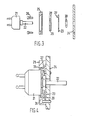
- a rotary variable electrical resistance device e.g. a potentiometer
- a housing 1 of metal or rigid plastics material containing an arcuate element of electrical resistance material (not shown) adapted to be traversed by a wiper of electrically conductive material (not shown), the wiper being operated by a rotatable spindle 2 arranged for rotation in bearings 3 and 4 in the housing 1, to adjust the setting of the device.
- a rotatable spindle 2 arranged for rotation in bearings 3 and 4 in the housing 1, to adjust the setting of the device.
- the spindle 2 is rigidly secured, by means of a solid coupling 5, to the end of a rotatably supported shaft 6 whose angular rotation is to be followed by the variable resistance device.
- Shaft 6 may comprise, for example, a throttle control shaft of an internal combustion engine in a motor vehicle, the setting of the variable resistance device being required to be changed by rotation of the throttle control shaft, for effecting control functions in the operation of the engine.
- the coupled spindle 2 and shaft 6 have a common axis 7.
- the shaft 6 supports the variable resistance device.
- a rigid member in the form of a pin 8 is secured at one end into a fixed support 9 which suitably comprises a metal plate or bracket.
- the end of the pin 8 is suitably threaded and engages a similarly threaded hole in the support 9.
- the housing 1 of the variable resistance device is provided with a lug or flange 10 extending therefrom and having a hole 11 through it.
- the variable resistance device is arranged such that the spindle 2 passes through a hole 12 provided in the support 9 and such that the pin 8 locates in the hole in the lug or flange 10.
- This simple arrangement is advantageous since it allows the variable resistance device to be displaced to follow any longitudinal displacement (i.e. in the direction indicated by arrows A, B) or lateral displacement (i.e. in the direction indicated by arrows C, D and E, F) of the end of shaft 6 which is coupled to the spindle 2, such displacement of the shaft taking place as a result of play in bearings which support it.
- the arrangement also allows the variable resistance device to tilt to accommodate a situation where the shaft 6 is not perpendicular to the support 9, or as a result of the shaft 6 being bent.
- a suitably resilient material such as a spring or rubber (e.g. silicone rubber) can be applied between the pin and sides of the hole to take up the clearance whilst permitting the necessary displacement to occur.
- pin 8 is shown in Figures 1 and 2 as having parallel sides, it may be advantageous for the pin to be formed of a barrel shape, thereby minimising risk of the pin jamming in the hole 11 when the housing 1 of the device is caused to be tilted.
- One or more further lugs or flanges 13, similar to lug or flange 10 may be provided, having a hole 14 therein.
- Such lugs or flanges 10, 14 are often already provided during manufacture of the device and hitherto intended for use in rigidly securing the device to a support.
- a screw 15 with a head 16 is passed through hole 14 in lug 13 and screwed into a hole provided in support 9.
- the head 16 of the screw is arranged to be sufficiently clear of the lug 13 to permit the required degree of displacement of the device, whilst serving to prevent the spindle 2 from becoming decoupled from the shaft 6, e.g. in event of the arrangement being utilised in conditions of severe vibration. It would be preferable to provide at least two further lugs 13 with screws 15, for this purpose.
- a pin with a head may be substituted, the head engaging the hole 11 in lug 10.
- the head of the pin is radiused to provide a barrel shape to prevent head jamming in the hole when the housing 1 is caused to be tilted.
- variable resistance device it may be necessary, for some applications, to preset the variable resistance device to allow a particular phasing between the device and the shaft coupled thereto. This may be achieved by providing a slot in the support 9 and providing one or more lock nuts on the end of the pin 8. Thus, with the lock nuts slack, the housing 1 of the device is rotated, the pin 8 being moved in the slot in support 9 during this rotation. When a desired setting of the device is attained, the pin is locked in place in the support 9 by means of the lock nuts.
- the housing of the device can be mounted on a sub-plate such that it can be rotated to a required position on the sub-plate and then clamped, a hole or recess being provided in the sub-plate into which pin 8 locates, operation being otherwise the same as described with reference to Figures 1 and 2.
- the pin 8 could be secured to lug or flange 10 or directly to the face of the housing of the device and be arranged to be located in a hole provided in the support 9.
- a disc or plate (not shown) could be clamped to the support and provided with an aperture for location by the pin, thus obviating the need to provide an aperture in the support for this purpose.
- This arrangement also permits a predetermined orientation of the device with respect to the support to be achieved which is valuable for phasing purposes.
- a flat spring blade could be substituted which would be secured at one end to the support 9 and at the other end to the side of the housing 1, lug 10 being unnecessary in such in embodiment.
- This arrangement would permit lateral displacements of the end of shaft 6 to be accommodated, but in the case where longitudinal displacements of the shaft are also required to be accommodated, the end of the spring blade could be slideably secured in a slot or groove in the side of housing 1 or in the support 9.
- a band of metal or plastics material could be provided encircling, but spaced from, the housing and secured to support 9, a suitably resilient material, such as silicone rubber, provided between the band and housing to permit displacement of the device whilst restraining the housing from rotating about the axis of the spindle 2.
- variable resistance devices could be provided arranged in ganged form on a common spindle axis and each provided with the means restraining the housing from rotation whilst permitting displacement to follow displacement of a shaft coupled to a spindle at one end of the ganged assembly.
- each of the ganged devices is provided with a lug or flange, as denoted by reference numeral 10 in Figures 1 and 2, then a single pin 8, extended to pass through the holes in the lugs of all the devices, could be used to allow displacement of the assembly when displacement of the end of the shaft coupled thereto occurs.
- a rotary variable electrical resistance device e.g. a potentiometer
- a rotary variable electrical resistance device is constructed comprising a housing 21 of metal or rigid plastics material containing essential elements as previously described with reference to Figures 1 and 2.
- a rotatable spindle 22 extends from the housing for adjusting the setting of the device, spindle 22 being intended to be rigidly coupled to the end of a rotatably supported shaft (such as the shaft 6 shown in Figures 1 and 2) whose angular rotation is to be followed by the variable resistance device.
- a disc shaped member 23 is arranged to be clamped at its periphery to a support 24 by means of a stepped ring shaped member 25, using screws 26 for securement of the member 25 to the support 24.
- a pin 27 extends from the disc shaped member 23 for location in an aperture 28 provided in a circular flange member 29 having a hole through its center and secured to the housing 21 of the device, concentrically with the spindle 22, by means of nut 30.
- the disc shaped member 23 and support 24 each have a hole therein through which the spindle 22 may pass.
- the flange member 29 is shaped for location within the stepped ring shaped member 25 such that clearance is provided at region 31 between the flange member 29.and ring shaped member 25 to permit the device 21, 22 to be displaced to follow any longitudinal and/or lateral displacement of a shaft secured to the spindle 22.
- the pin 27, located in aperture 28 in the flange member 29, restrains the housing 21 from rotation about the axis of the spindle 22 when the latter is rotated.
- pin 27 may be provided on the disc shaped member 23 instead of pin 27 being provided on the disc shaped member 23, it may be provided extending from the flange member 29 and arranged to be located in an aperture provided in the disc shaped member 23. With this arrangement, the disc shaped member 23 may be eliminated if desired and the pin located in an aperture provided in the support 24. In this latter case the ring shaped member 25 would be secured to the support 24 without the intermediary of the disc shaped member 23.
- a further advantage of the present invention is particularly evident where a variable resistance device is operated in conditions where mechanical vibration exists.
- a device of the prior art is rigidly mounted and coupled to an operating shaft, such vibration sometimes results in what is known in the art as 'dither'.
- a small amount of slackness or resilience in the coupling between the housing of the device and support advantageously attenuates the effect of such vibrations and reduces the effect of 'dither' wear on the resistance track.
Landscapes
- Engineering & Computer Science (AREA)
- Microelectronics & Electronic Packaging (AREA)
- Adjustable Resistors (AREA)
Claims (20)
Priority Applications (2)
| Application Number | Priority Date | Filing Date | Title |
|---|---|---|---|
| DE8181303475T DE3174395D1 (en) | 1981-07-28 | 1981-07-28 | Variable electrical resistance device |
| EP19810303475 EP0070934B1 (de) | 1981-07-28 | 1981-07-28 | Einstellbarer Widerstand |
Applications Claiming Priority (1)
| Application Number | Priority Date | Filing Date | Title |
|---|---|---|---|
| EP19810303475 EP0070934B1 (de) | 1981-07-28 | 1981-07-28 | Einstellbarer Widerstand |
Publications (2)
| Publication Number | Publication Date |
|---|---|
| EP0070934A1 EP0070934A1 (de) | 1983-02-09 |
| EP0070934B1 true EP0070934B1 (de) | 1986-04-16 |
Family
ID=8188360
Family Applications (1)
| Application Number | Title | Priority Date | Filing Date |
|---|---|---|---|
| EP19810303475 Expired EP0070934B1 (de) | 1981-07-28 | 1981-07-28 | Einstellbarer Widerstand |
Country Status (2)
| Country | Link |
|---|---|
| EP (1) | EP0070934B1 (de) |
| DE (1) | DE3174395D1 (de) |
Families Citing this family (3)
| Publication number | Priority date | Publication date | Assignee | Title |
|---|---|---|---|---|
| GB2180699B (en) * | 1985-09-17 | 1988-12-07 | Crystalate Electronics | Potentiometer |
| DE4221024C2 (de) * | 1992-06-26 | 1995-11-30 | Ruf Kg Wilhelm | Haltevorrichtung zur Lagerung eines durch eine drehbare Welle betätigbaren elektrischen Bauteils an einem Gegenstand |
| JPH10101368A (ja) * | 1996-10-01 | 1998-04-21 | Nippon Sheet Glass Co Ltd | 紫外線赤外線吸収ガラス |
Family Cites Families (4)
| Publication number | Priority date | Publication date | Assignee | Title |
|---|---|---|---|---|
| US2921285A (en) * | 1959-01-19 | 1960-01-12 | Oilgear Co | Preset transducer assembly |
| JPS5821126Y2 (ja) * | 1976-08-06 | 1983-05-04 | 電気音響株式会社 | ポテンシヨメ−タ |
| US4250481A (en) * | 1978-11-21 | 1981-02-10 | Kaufman Lance R | Variable resistance device for thick film circuitry |
| GB2067846B (en) * | 1980-01-12 | 1983-06-02 | Colvern Ltd | Variable electrical resistance device |
-
1981
- 1981-07-28 DE DE8181303475T patent/DE3174395D1/de not_active Expired
- 1981-07-28 EP EP19810303475 patent/EP0070934B1/de not_active Expired
Also Published As
| Publication number | Publication date |
|---|---|
| DE3174395D1 (en) | 1986-05-22 |
| EP0070934A1 (de) | 1983-02-09 |
Similar Documents
| Publication | Publication Date | Title |
|---|---|---|
| US4373269A (en) | Adjustment mechanism | |
| KR100622612B1 (ko) | 하나 이상의 광학소자를 갖는 광학 결상 장치 | |
| US4520987A (en) | Structure of supporting a stepping motor | |
| WO1998037612A1 (de) | Haltevorrichtung für einen elektromotor | |
| EP0070934B1 (de) | Einstellbarer Widerstand | |
| US10760667B2 (en) | Transmission housing unit having an axial disk | |
| US4400686A (en) | Variable electrical resistance device | |
| GB2058943A (en) | Cooling fan assemblies | |
| GB2067846A (en) | Variable electrical resistance device | |
| JPS62189679A (ja) | リミツト・ストツプ装置 | |
| US4052746A (en) | Head assembly for magnetic recorders | |
| US5079685A (en) | Lamp assembly | |
| EP0964812B1 (de) | Verbesserungen in bezug auf lenkvorrichtungen | |
| CN111479743A (zh) | 用于机动车辆的电动可调节的转向柱 | |
| JPH0817135A (ja) | スピンドルモータ固定機構 | |
| US4202575A (en) | Door handle mechanisms | |
| US2872553A (en) | Mechanical stop for potentiometers | |
| US4884882A (en) | Apparatus for positioning optical elements | |
| SE508909C2 (sv) | System för att centrera ett roterande element | |
| EP0194803B1 (de) | Regulieranordnung für einen Magnetkopf | |
| US2816968A (en) | Distributor structure | |
| US3936882A (en) | Adjustable mounting arrangement for recording head | |
| JPS629097A (ja) | 可変調整機構 | |
| CN110855086A (zh) | 电动机的轴承端板上用于解角器的保持装置 | |
| US3745272A (en) | Contact breaker assembly with improved adjustable distributor mounting plate and locking plate means |
Legal Events
| Date | Code | Title | Description |
|---|---|---|---|
| PUAI | Public reference made under article 153(3) epc to a published international application that has entered the european phase |
Free format text: ORIGINAL CODE: 0009012 |
|
| AK | Designated contracting states |
Designated state(s): BE DE FR IT NL SE |
|
| 17P | Request for examination filed |
Effective date: 19830805 |
|
| RAP1 | Party data changed (applicant data changed or rights of an application transferred) |
Owner name: CRYSTALATE ELECTRONICS LIMITED |
|
| ITF | It: translation for a ep patent filed | ||
| GRAA | (expected) grant |
Free format text: ORIGINAL CODE: 0009210 |
|
| AK | Designated contracting states |
Kind code of ref document: B1 Designated state(s): BE DE FR IT NL SE |
|
| PG25 | Lapsed in a contracting state [announced via postgrant information from national office to epo] |
Ref country code: NL Effective date: 19860416 Ref country code: FR Free format text: THE PATENT HAS BEEN ANNULLED BY A DECISION OF A NATIONAL AUTHORITY Effective date: 19860416 Ref country code: BE Effective date: 19860416 |
|
| PG25 | Lapsed in a contracting state [announced via postgrant information from national office to epo] |
Ref country code: SE Effective date: 19860430 |
|
| REF | Corresponds to: |
Ref document number: 3174395 Country of ref document: DE Date of ref document: 19860522 |
|
| EN | Fr: translation not filed | ||
| NLV1 | Nl: lapsed or annulled due to failure to fulfill the requirements of art. 29p and 29m of the patents act | ||
| PLBE | No opposition filed within time limit |
Free format text: ORIGINAL CODE: 0009261 |
|
| STAA | Information on the status of an ep patent application or granted ep patent |
Free format text: STATUS: NO OPPOSITION FILED WITHIN TIME LIMIT |
|
| 26N | No opposition filed | ||
| PG25 | Lapsed in a contracting state [announced via postgrant information from national office to epo] |
Ref country code: DE Effective date: 19870401 |