EP0070275B1 - An ejector device for stores - Google Patents
An ejector device for stores Download PDFInfo
- Publication number
- EP0070275B1 EP0070275B1 EP19810901601 EP81901601A EP0070275B1 EP 0070275 B1 EP0070275 B1 EP 0070275B1 EP 19810901601 EP19810901601 EP 19810901601 EP 81901601 A EP81901601 A EP 81901601A EP 0070275 B1 EP0070275 B1 EP 0070275B1
- Authority
- EP
- European Patent Office
- Prior art keywords
- lug
- collar
- store
- retaining means
- tubular member
- Prior art date
- Legal status (The legal status is an assumption and is not a legal conclusion. Google has not performed a legal analysis and makes no representation as to the accuracy of the status listed.)
- Expired
Links
Images


Classifications
-
- B—PERFORMING OPERATIONS; TRANSPORTING
- B64—AIRCRAFT; AVIATION; COSMONAUTICS
- B64D—EQUIPMENT FOR FITTING IN OR TO AIRCRAFT; FLIGHT SUITS; PARACHUTES; ARRANGEMENTS OR MOUNTING OF POWER PLANTS OR PROPULSION TRANSMISSIONS IN AIRCRAFT
- B64D1/00—Dropping, ejecting, releasing, or receiving articles, liquids, or the like, in flight
- B64D1/02—Dropping, ejecting, or releasing articles
- B64D1/04—Dropping, ejecting, or releasing articles the articles being explosive, e.g. bombs
- B64D1/06—Bomb releasing; Bombs doors
Definitions
- the invention relates to the field of store ejectors for an aircraft, and particularly to a device which both supports and ejects the stores.
- a stores rack must provide a suspension support that has a highly reliable releasing mechanism. Furthermore, on modern highspeed, and particularly supersonic aircraft, the capability to forcibly eject the weapon from the rack must be provided, for gravity release is often unsafe at these speeds. This is because the airflow around the aircraft is so turbulent that there is a tendency for the store to either "fly" along with the aircraft or change pitch angle; or even hit other stores. Because of this turbulent airflow and, additionally, to resist high G loads, sway bracing in the lateral plane is a necessity. The three basic functions, suspension, ejection, and sway-bracing, are usually accomplished by separate components within the bomb rack.
- Atypical stores suspension system is disclosed in US ⁇ A ⁇ 3,883,097, "Device for Picking Up and Ejecting Loads Under an Airplane", by Billot.
- Billot uses a ball detent device which engages recesses within the weapon. Release is accomplished by withdrawing a cam within the detent, allowing the balls to withdraw. But, because of the internal cam and linkage system, a separate store ejector mechanism is required. This, of course, adds weight to the aircraft.
- Another example of a bomb rack having separate suspension and ejecting mechanisms is US ⁇ A ⁇ 4,049,222, “Ejector Rack for Nuclear Stores", by Peterson.
- Newell discloses a system wherein a pair of jaws engage a lug on the store, and are held in contact with the lug by a pair of roller cams. A spring-biased plunger in contact with the lug is used for ejection. Upon actuation, the roller cams are moved to a position whereby the jaws may open due to the weight of the weapon itself. After the jaws have opened, the spring-biased plunger ejects the store. Newell's design has no safety provisions to prevent inadvertent release of the weapon. Furthermore, there is no integral sway bracing. Finally, the overall system is quite bulky.
- Geffner discloses an ejector assembly movably mounted in a housing and secured in the retracted position by a ball detent assembly.
- the ejector assembly is explosively actuated, but movement is prevented by the detent so that inadvertent actuation of the explosive cartridge will not release the store.
- the suspension means is a rotating hook mounted at the end of the ejector assembly. In the retracted position, a cam at the opposite end of the hook is locked into engagement with the lug on the store by a retainer cup on the housing.
- Actuation is accomplished by release of the detent which allows the ejector assembly to' extend, releasing the hook. Upon actuation of the cartridge the stores are ejected. While Geffner does provide additional safety features it is extremely complicated and, further, does not provide integral sway bracing.
- a still further example of a device for releasably engaging a store is disclosed in US ⁇ A ⁇ 31 81 908.
- This known device comprises a tubular member having an internal bore and further a plurality of lug retaining means. Also, an ejector ram is movably mounted in said bore.
- a still further object of this invention is to provide a stores suspension system with integral ejector and sway brace which is both compact and reliable.
- the invention relates to a device for releasably engaging a store as defined in claim 1.
- the retaining means preferably comprises a plurality of resilient lug retaining fingers attached to the tubular member extending about its longitudinal axis and terminating in protrusions which are directed inwardly toward the longitudinal axis.
- the plurality of retaining fingers are movable from a first position, wherein notches in the protrusions engage a lug mounted on the store, to a second position wherein the notches are disengaged from the plug.
- a collar is mounted about the tubular member and movable along the longitudinal axis of the tubular member from a first position, wherein the collar holds the retaining fingers in their first position, to a second position, wherein the collar is disengaged from the retaining fingers.
- At least one first fluid pressure cylinder is provided having a first piston therein coupled to the collar.
- a second fluid pressure cylinder is provided having a piston therein coupled to an ejector ram movably mounted within the bore of the tubular member.
- the first and second cylinders are provided with first and second gas generators preferably in the form of explosive cartridges.
- the first gas generator is adapted to fire before the second gas generator, thereby causing the collar to be moved from the first to the second position.
- the ejector ram Upon actuation of the second gas generator, the ejector ram is driven toward the lug causing the resilient fingers to move from the first position to the second position, and then strike the lug, thereby forcibly ejecting the store.
- the collar incorporates a surface adapted to mate with a surface on the store with both surfaces being substantially perpendicular to the longitudinal axis of the tubular member, such that the collar acts as a sway brace when in thefirst position.
- the lug incorporated in a receptacle within the store, having a vertical wall substantially parallel to the longitudinal axis of the tubular member.
- the collar is provided with a mating tubular surface adapted to slidably engage the wall, providing additional sway bracing.
- Fig. 1 is a side elevation view of a stores rack partially broken away to show the interior thereof wherein are mounted a pair of combination store suspension, ejector, and sway brace devices, with the forward device shown supporting a store, and the rear device shown in the actuated position.
- FIG. 2 Illustrated in Fig. 2 is a cross-sectional view of the forward device shown in Fig. 1 along the line 2-2.
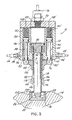
- FIG. 3 Illustrated in Fig. 3 is a cross-sectional view of the forward device shown in Fig. 1 along the line 2-2 showing the device in the actuated position.
- FIG. 1 Illustrated in Fig. 1 is a side elevation view of a store rack designated by numeral 10 partially broken away to show forward and rear combination suspension, ejection and sway brace devices 12 and 12a for a store 14.
- FIG. 2 Illustrated in Fig. 2 is a cross-sectional view of the device 12 shown in Fig. 1 along the lines 2-2.
- the store 14 incorporates a standard internally threaded lug attaching receptacle 16.
- the recess 16 is a standard size adapted to accommodate most attaching fittings or lugs.
- Installed in the receptacle 16 is an externally threaded lug fitting 20 in the shape of a cylindrical cup having a lug 22 mounted in the center.
- the lug 22 comprises a stem portion 24 on top of which is attached a disc portion 26.
- the device 12 comprises a main body 28 attached to the rack 10 by fastener means (not shown).
- An externally threaded tubular member 30, having a longitudinal axis 31, is engaged to the internally threaded wall of cavity 34 in the body 28.
- the bottom portion of the member 30 incorporates a plurality of substantially equally spaced longitudinal slots 40 dividing the lower end of the member 30 into a plurality of resilient lug retaining fingers 42, shown in a first position, in engagement with lug 22.
- the retaining fingers 42 terminate in protrusions 44 extending inwardly toward the longitudinal axis 31, having internal notches 46 adapted to engagethe disc portion 26 of the lug 22.
- an ejector ram 50 Movably mounted within a bore 45 of the member 30 is an ejector ram 50 which extends into an actuation cylinder 51 in the body 28 and terminates at one end (furthest from lug 22) in a piston 54.
- the ram 50 is biased to the upward position by spring 56 which is positioned around ram 50 and bears against piston 54 at one end and end 52 of cylinder 51.
- a seal in the form of "0" ring 58 mounted in groove 59 seals the upper side 60 from the lower side 62 of the piston 54.
- the cylinder 51 is sealed by a cap 64 and gasket 66 secured to the body 28 by means of fasteners (not shown).
- the cap 64 incorporates an internally threaded port 68 in which is mounted a pressure generator preferably in the form of a replaceable electrically initiated gas generating explosive cartridge 70. Attached to the cartridge 70 is an electrical connector 72 which is coupled to an electrical power supply (not shown).
- a vent port 74 is provided in the body 28 to ensure that no pressure can be built on the side 62 of the piston 54, which might create a resistance to ram travel.
- a collar 76 is slidably mounted to the tubular member 30 via aperture 78 therein.
- the collar 76 incorporates two clevis members 80 and 80'.
- a pair of piston rods, 82 and 82' are provided having apertures 83 and 83' at their lower ends 84 and 84' respectively, and are joined to the clevis members 80 and 80' by means of clevis pins 85 and 85' respectively.
- the piston rods 82 and 82' are coupled to pistons 86 and 86' mounted within second pressure cylinders 88 and 88' respectively.
- the collar 76 is biased downward to a first position wherein the collar locks the retaining fingers 42 into engagement with the lug 22, by means of springs 90 and 90' respectively positioned within cylinders 88 and 88', which bear against cap 64 and pistons 86 and 86'.
- the upper sides 100 and 100' of pistons 86 and 86' are vented to the atmosphere via ports 102 and 102' within the cap 64.
- the vents are provided to assure that no pressure can be built up on the upper sides 100 and 100' in offering resistance to the movement of the collar 76. While the use of two second pressure cylinders 88 and 88' are preferred because the tendency of the collar 76 to twist and bind about retaining fingers 42 is eliminated, it is possible to use only one.
- the collar76 can also be adapted to act as a sway brace.
- a shoulder 102 substantially perpendicular to the longitudinal axis 31 is provided on collar 76 adapted to mate with. surface 104 on the lug fitting 20.
- Additional sway bracing can be provided by adapting the tubular portion 106 of the collar 76 to slidably engage the wall 108 of the lug fitting 20.
- Figs. 1 and 2 and additionally to Fig. 3 which is the cross-sectional view of the mechanism shown in Fig. 2, but in the actuated position, the functioning of the mechanism can be easily understood.
- the store 14 is installed in the following manner.
- the cartridge 98 is removed from the port 96 and a suitable source of pressurizing fluid such as compressed air or hydraulic fluid is coupled to the port 96.
- the pressure is applied to piston 86 which will move the collar 76 upward until it bottoms against surfact 110 of the body 28 (from the first to the second position). This frees the retaining fingers 42.
- the store 14 is raised until the disc portion 26 of the lug 22 engages an inclined surface 116 on the protrusion 44.
- the fingers 42 must be made of a suitable high strength material such as 17-4 corrosion resistant steel heat treated to 200,000 psi in orderto support the load without having the collar 76 in the first position.
- the pressure on the piston 86 is reduced, allowing the spring 90 to force the collar to the first position aboutthe retaining fingers 42 such that surface 102 of the collar 76 contacts surface 104 of the lug fitting 20.
- the cartridge 98 is reinserted into the port 96 and electrically connected by attachment of connector 99. It is normal practice to simultaneously mount the store 14 to both the front and rear devices 12 and 12a. Because of possible tolerance build-ups between the devices and between the lugs on the store 14 it may be desirable to provide means (not shown) to adjust the position of one of the devices to accommodate such tolerances.
- an electrical signal from the power supply (not shown) is sent to cartridges 98 and 98' causing them to ignite, producing sufficient gas pressure to drive pistons 86 and 86', and collar 76 upward to the second position.
- a second electrical signal is then generated, timed to reach cartridge 70 after the collar76 contacts surface 110 of the body 28, i.e., the second position.
- the resulting gas pressure forces piston 54 downward such that ram 50 engages an inclined surface 118 of the protrusion 44, causing the retaining fingers 42 to again spread apart to the second position, where the notch 46 disengages from the disc portion 26 of the lug 22, freeing the store 14.
- the continued downward movement of the ram 50 causes it to strike the lug 22 physically ejecting the load 14.
- the device 12a shown in Fig. 1 also illustrates this position. Here it can be seen that the collar 76a is in the second position and a ram 50a extended, forcing the retaining fingers 42a to the second position.
- Small diameter bleed ports 120 and 120' are provided in the body 28 for venting ports 96 and 96', respectively, to atmosphere.
- a bleed port 122 is provided in cap 64 for venting the portion of the cylinder 51 above the piston 54to atmosphere.
- the bleed ports 120,120' and 122 are made sufficiently small so as to-have little effect on pressure buildup within cylinders 88, 88' and 51 upon ignition of the cartridges 98, 88' and 70, respectively, but after release of the store 14 allow the pressure within the cylinders to return to ambient. After the pressure from the cartridges 70, 98 and 98' has been reduced to ambient (or during the pressure reduction), the spring 56 will raise the ram 50tothe upward position, and springs 90 and 90' will force the collar 76 to the first position.
- the cartridge 70 is inadvertently actuated with the collar 76 in the first position, the store 14 will remain secured to the stores rack 10. Even though the ram 50 will be driven into the protrusions 46 of the retaining fingers 42, the fingers are locked in the first position and the ram will be prevented from traveling further. This is an important safety feature not found in many prior art systems.
- the gas pressure, produced by the cartridge 70 can be changed by varying the explosive charge therein to accommodate different size stores. Furthermore, instead of having the electrical power applied to the cartridges 98, 98' and 70 in sequence, they can be fired simultaneously if cartridge 70 incorporates a suitable explosive delay column (not shown). Furthermore, while the device 12 has been shown using explosively actuated pressure generators, it should be understood that hydraulic or pneumatic pressure could be used to actuate the ram 50 and position collar 76.
- the invention has application on aircraft designed to release stores while airborne.
Description
- The invention relates to the field of store ejectors for an aircraft, and particularly to a device which both supports and ejects the stores.
- A stores rack must provide a suspension support that has a highly reliable releasing mechanism. Furthermore, on modern highspeed, and particularly supersonic aircraft, the capability to forcibly eject the weapon from the rack must be provided, for gravity release is often unsafe at these speeds. This is because the airflow around the aircraft is so turbulent that there is a tendency for the store to either "fly" along with the aircraft or change pitch angle; or even hit other stores. Because of this turbulent airflow and, additionally, to resist high G loads, sway bracing in the lateral plane is a necessity. The three basic functions, suspension, ejection, and sway-bracing, are usually accomplished by separate components within the bomb rack.
- Atypical stores suspension system is disclosed in US―A―3,883,097, "Device for Picking Up and Ejecting Loads Under an Airplane", by Billot. Billot uses a ball detent device which engages recesses within the weapon. Release is accomplished by withdrawing a cam within the detent, allowing the balls to withdraw. But, because of the internal cam and linkage system, a separate store ejector mechanism is required. This, of course, adds weight to the aircraft. Another example of a bomb rack having separate suspension and ejecting mechanisms is US―A― 4,049,222, "Ejector Rack for Nuclear Stores", by Peterson.
- There are numerous prior art methods of combining ejection and suspension systems. For example, US―A―3,877,343, "Stores Carriers", by Newell, et al. Newell discloses a system wherein a pair of jaws engage a lug on the store, and are held in contact with the lug by a pair of roller cams. A spring-biased plunger in contact with the lug is used for ejection. Upon actuation, the roller cams are moved to a position whereby the jaws may open due to the weight of the weapon itself. After the jaws have opened, the spring-biased plunger ejects the store. Newell's design has no safety provisions to prevent inadvertent release of the weapon. Furthermore, there is no integral sway bracing. Finally, the overall system is quite bulky.
- Another example is provided in US-A-3,810,671, "Jettison Device for Helicopter Load Carrying System", by Jeffery. The Jeffery device comprises a housing in which a pair of jaws are locked into engagement with a lug mounted on a store by an explosively actuated piston rod. Upon actuation, movement of the piston rod releases the jaws and the rod ejects the store pushing the jaws out of the way. As in the previous example, there is no method of preventing inadvertent actuation and, additionally, no integral sway bracing. Furthermore, Jeffery's concept would be somewhat difficult to reset.
- A further example of a combined suspension and ejector system can be found in US-A--3,059,956, "Combined Shackle and Ejector Mechanism for Stores", by Geffner. Geffner discloses an ejector assembly movably mounted in a housing and secured in the retracted position by a ball detent assembly. The ejector assembly is explosively actuated, but movement is prevented by the detent so that inadvertent actuation of the explosive cartridge will not release the store. The suspension means is a rotating hook mounted at the end of the ejector assembly. In the retracted position, a cam at the opposite end of the hook is locked into engagement with the lug on the store by a retainer cup on the housing. Actuation is accomplished by release of the detent which allows the ejector assembly to' extend, releasing the hook. Upon actuation of the cartridge the stores are ejected. While Geffner does provide additional safety features it is extremely complicated and, further, does not provide integral sway bracing.
- A still further example of a device for releasably engaging a store is disclosed in US―A― 31 81 908. This known device comprises a tubular member having an internal bore and further a plurality of lug retaining means. Also, an ejector ram is movably mounted in said bore.
- Other examples of stores racks are: US-A--3,009,730, "Ejector for External Carried Stores", by Gantschnigg, et al.; US-A-3,435,725, "Store Launching System", by Miller; US-A-2,949,822, "Bomber Lease Mechanism", by Mus- ser; and US―A―3,610,094, "Ejector Release Units for Release in Aircraft", by Graigie.
- High speed maneuvers and airflow induced vibrations also induce loads in the lateral plane, which, also, must be absorbed. Thus, sway braces are provided to restrain the store in the lateral plane. These are normally forged arms protruding from the rack with manually adjustable pads to accommodate varying store diameters. A typical prior art sway brace is disclosed in the Geffner reference. Manually adjusting such sway braces is time consuming for they are often difficult to reach within store bays because of limited access: It is obvious from this brief review of the prior art that there exists no highly reliable combination ejector, suspension, and sway brace mechanism for an aircraft mounted stores rack, which also provides increased safety in that inadvertent actuation of the ejector system will not release the store.
- It is, therefore, a primary object of this invention to provide a store suspension system having an integral stores ejector.
- It is another object of this invention to provide a store suspension system having both an integral ejector and stores sway brace.
- It is a further object of this invention to provide a store suspension system in combination with a stores ejector which incorporates a safety interlock which will prevent inadvertent ejection.
- A still further object of this invention is to provide a stores suspension system with integral ejector and sway brace which is both compact and reliable.
- The invention relates to a device for releasably engaging a store as defined in claim 1.
- The retaining means preferably comprises a plurality of resilient lug retaining fingers attached to the tubular member extending about its longitudinal axis and terminating in protrusions which are directed inwardly toward the longitudinal axis. The plurality of retaining fingers are movable from a first position, wherein notches in the protrusions engage a lug mounted on the store, to a second position wherein the notches are disengaged from the plug. A collar is mounted about the tubular member and movable along the longitudinal axis of the tubular member from a first position, wherein the collar holds the retaining fingers in their first position, to a second position, wherein the collar is disengaged from the retaining fingers.
- At least one first fluid pressure cylinder is provided having a first piston therein coupled to the collar. A second fluid pressure cylinder is provided having a piston therein coupled to an ejector ram movably mounted within the bore of the tubular member. The first and second cylinders are provided with first and second gas generators preferably in the form of explosive cartridges. The first gas generator is adapted to fire before the second gas generator, thereby causing the collar to be moved from the first to the second position. Upon actuation of the second gas generator, the ejector ram is driven toward the lug causing the resilient fingers to move from the first position to the second position, and then strike the lug, thereby forcibly ejecting the store.
- Preferably, the collar incorporates a surface adapted to mate with a surface on the store with both surfaces being substantially perpendicular to the longitudinal axis of the tubular member, such that the collar acts as a sway brace when in thefirst position.
- It is also preferred to have the lug incorporated in a receptacle within the store, having a vertical wall substantially parallel to the longitudinal axis of the tubular member. The collar is provided with a mating tubular surface adapted to slidably engage the wall, providing additional sway bracing.
- The novel features which are believed to be characteristic of the invention, both as to its organization and its method of operation, together with further objects and advantages thereof, will be better understood from the following description in connection with the accompanying drawings in which a presently preferred embodiment of the invention is illustrated by way of example. It is to be expressly understood, however, that the drawings are for purposes of illustration and description only, and are not intended as a definition of the limits of the invention.
- Fig. 1 is a side elevation view of a stores rack partially broken away to show the interior thereof wherein are mounted a pair of combination store suspension, ejector, and sway brace devices, with the forward device shown supporting a store, and the rear device shown in the actuated position.
- Illustrated in Fig. 2 is a cross-sectional view of the forward device shown in Fig. 1 along the line 2-2.
- Illustrated in Fig. 3 is a cross-sectional view of the forward device shown in Fig. 1 along the line 2-2 showing the device in the actuated position.
- Illustrated in Fig. 1 is a side elevation view of a store rack designated by numeral 10 partially broken away to show forward and rear combination suspension, ejection and sway
brace devices store 14. Illustrated in Fig. 2 is a cross-sectional view of thedevice 12 shown in Fig. 1 along the lines 2-2. It can be seen that thestore 14 incorporates a standard internally threadedlug attaching receptacle 16. Therecess 16 is a standard size adapted to accommodate most attaching fittings or lugs. Installed in thereceptacle 16 is an externally threaded lug fitting 20 in the shape of a cylindrical cup having alug 22 mounted in the center. Thelug 22 comprises astem portion 24 on top of which is attached adisc portion 26. - The
device 12 comprises amain body 28 attached to therack 10 by fastener means (not shown). An externally threadedtubular member 30, having alongitudinal axis 31, is engaged to the internally threaded wall of cavity 34 in thebody 28. The bottom portion of themember 30 incorporates a plurality of substantially equally spacedlongitudinal slots 40 dividing the lower end of themember 30 into a plurality of resilientlug retaining fingers 42, shown in a first position, in engagement withlug 22. The retainingfingers 42 terminate inprotrusions 44 extending inwardly toward thelongitudinal axis 31, having internal notches 46 adapted toengagethe disc portion 26 of thelug 22. - Movably mounted within a bore 45 of the
member 30 is anejector ram 50 which extends into an actuation cylinder 51 in thebody 28 and terminates at one end (furthest from lug 22) in apiston 54. Theram 50 is biased to the upward position byspring 56 which is positioned aroundram 50 and bears againstpiston 54 at one end and end 52 of cylinder 51. - A seal in the form of "0" ring 58 mounted in
groove 59 seals theupper side 60 from the lower side 62 of thepiston 54. The cylinder 51 is sealed by acap 64 andgasket 66 secured to thebody 28 by means of fasteners (not shown). Thecap 64 incorporates an internally threadedport 68 in which is mounted a pressure generator preferably in the form of a replaceable electrically initiated gas generatingexplosive cartridge 70. Attached to thecartridge 70 is anelectrical connector 72 which is coupled to an electrical power supply (not shown). A vent port 74 is provided in thebody 28 to ensure that no pressure can be built on the side 62 of thepiston 54, which might create a resistance to ram travel. - A
collar 76 is slidably mounted to thetubular member 30 viaaperture 78 therein. Thecollar 76 incorporates twoclevis members 80 and 80'. A pair of piston rods, 82 and 82', are provided havingapertures 83 and 83' at their lower ends 84 and 84' respectively, and are joined to the clevismembers 80 and 80' by means of clevis pins 85 and 85' respectively. Thepiston rods 82 and 82' are coupled topistons 86 and 86' mounted withinsecond pressure cylinders 88 and 88' respectively. Thecollar 76 is biased downward to a first position wherein the collar locks the retainingfingers 42 into engagement with thelug 22, by means ofsprings 90 and 90' respectively positioned withincylinders 88 and 88', which bear againstcap 64 andpistons 86 and 86'. - The
lower sides 87 and 87' ofpistons 86 and 86' are sealed off by means of "O" rings 92 and 92' mounted ingrooves 93 and 93' in thebody 28, and "0" rings 94 and 94' mounted in grooves 95 and 95' in thepistons 86 and 86'. Coupled to thelower sides 87 and 87' of thepistons 86 and 86' areports 96 and 96' which are adapted to receive second gas generators, preferably in the form of electrically initiated gas generatingexplosive cartridges 98 and 98' coupled to the electrical power supply (not shown) viaconnectors 99 and 99'. Theupper sides 100 and 100' ofpistons 86 and 86' are vented to the atmosphere viaports 102 and 102' within thecap 64. The vents are provided to assure that no pressure can be built up on theupper sides 100 and 100' in offering resistance to the movement of thecollar 76. While the use of twosecond pressure cylinders 88 and 88' are preferred because the tendency of thecollar 76 to twist and bind about retainingfingers 42 is eliminated, it is possible to use only one. - The collar76 can also be adapted to act as a sway brace. For example, a
shoulder 102 substantially perpendicular to thelongitudinal axis 31 is provided oncollar 76 adapted to mate with.surface 104 on the lug fitting 20. Additional sway bracing can be provided by adapting thetubular portion 106 of thecollar 76 to slidably engage thewall 108 of the lug fitting 20. - Still referring to Figs. 1 and 2 and additionally to Fig. 3 which is the cross-sectional view of the mechanism shown in Fig. 2, but in the actuated position, the functioning of the mechanism can be easily understood. Assuming that there is no
store 14 attached to thedevice 12, thestore 14 is installed in the following manner. Thecartridge 98 is removed from theport 96 and a suitable source of pressurizing fluid such as compressed air or hydraulic fluid is coupled to theport 96. The pressure is applied topiston 86 which will move thecollar 76 upward until it bottoms againstsurfact 110 of the body 28 (from the first to the second position). This frees the retainingfingers 42. Thestore 14 is raised until thedisc portion 26 of thelug 22 engages aninclined surface 116 on theprotrusion 44. Further raising of thestore 14 will cause thedisc 26 to slide up theinclined surface 116, forcing theretainer fingers 42 to spread apart to a second position, wherein thedisc 26 extendspastthe surface 116 allowing thefingers 42 to snap back with the notches 46 engaging thedisc 26 as shown in Fig. 2. - Safety requirements dictate that once so engaged, the
store 14 must be locked in place. Therefore, thefingers 42 must be made of a suitable high strength material such as 17-4 corrosion resistant steel heat treated to 200,000 psi in orderto support the load without having thecollar 76 in the first position. After theload 14 is in place, the pressure on thepiston 86 is reduced, allowing thespring 90 to force the collar to the first position aboutthe retainingfingers 42 such thatsurface 102 of thecollar 76 contacts surface 104 of the lug fitting 20. At this point thestore 14 is secured in place. Thecartridge 98 is reinserted into theport 96 and electrically connected by attachment ofconnector 99. It is normal practice to simultaneously mount thestore 14 to both the front andrear devices store 14 it may be desirable to provide means (not shown) to adjust the position of one of the devices to accommodate such tolerances. - To release the
store 14 an electrical signal from the power supply (not shown) is sent tocartridges 98 and 98' causing them to ignite, producing sufficient gas pressure to drivepistons 86 and 86', andcollar 76 upward to the second position. A second electrical signal is then generated, timed to reachcartridge 70 after the collar76 contacts surface 110 of thebody 28, i.e., the second position. The resulting gaspressure forces piston 54 downward such thatram 50 engages aninclined surface 118 of theprotrusion 44, causing the retainingfingers 42 to again spread apart to the second position, where the notch 46 disengages from thedisc portion 26 of thelug 22, freeing thestore 14. The continued downward movement of theram 50 causes it to strike thelug 22 physically ejecting theload 14. Thedevice 12a shown in Fig. 1 also illustrates this position. Here it can be seen that thecollar 76a is in the second position and a ram 50a extended, forcing the retainingfingers 42a to the second position. - Small diameter bleed
ports 120 and 120' are provided in thebody 28 for ventingports 96 and 96', respectively, to atmosphere. Ableed port 122 is provided incap 64 for venting the portion of the cylinder 51 above the piston 54to atmosphere. The bleed ports 120,120' and 122 are made sufficiently small so as to-have little effect on pressure buildup withincylinders 88, 88' and 51 upon ignition of thecartridges store 14 allow the pressure within the cylinders to return to ambient. After the pressure from thecartridges spring 56 will raise the ram 50tothe upward position, and springs 90 and 90' will force thecollar 76 to the first position. - It should be noted that the
cartridge 70 is inadvertently actuated with thecollar 76 in the first position, thestore 14 will remain secured to the stores rack 10. Even though theram 50 will be driven into the protrusions 46 of the retainingfingers 42, the fingers are locked in the first position and the ram will be prevented from traveling further. This is an important safety feature not found in many prior art systems. - It should also be noted that the gas pressure, produced by the
cartridge 70, can be changed by varying the explosive charge therein to accommodate different size stores. Furthermore, instead of having the electrical power applied to thecartridges cartridge 70 incorporates a suitable explosive delay column (not shown). Furthermore, while thedevice 12 has been shown using explosively actuated pressure generators, it should be understood that hydraulic or pneumatic pressure could be used to actuate theram 50 andposition collar 76. - The invention has application on aircraft designed to release stores while airborne.
Claims (7)
Applications Claiming Priority (1)
| Application Number | Priority Date | Filing Date | Title |
|---|---|---|---|
| PCT/US1981/000145 WO1982002527A1 (en) | 1981-01-26 | 1981-01-26 | An ejector device for stores |
Publications (3)
| Publication Number | Publication Date |
|---|---|
| EP0070275A1 EP0070275A1 (en) | 1983-01-26 |
| EP0070275A4 EP0070275A4 (en) | 1984-12-11 |
| EP0070275B1 true EP0070275B1 (en) | 1987-11-04 |
Family
ID=22161077
Family Applications (1)
| Application Number | Title | Priority Date | Filing Date |
|---|---|---|---|
| EP19810901601 Expired EP0070275B1 (en) | 1981-01-26 | 1981-01-26 | An ejector device for stores |
Country Status (4)
| Country | Link |
|---|---|
| EP (1) | EP0070275B1 (en) |
| DE (1) | DE3176507D1 (en) |
| GB (1) | GB2106225B (en) |
| WO (1) | WO1982002527A1 (en) |
Families Citing this family (6)
| Publication number | Priority date | Publication date | Assignee | Title |
|---|---|---|---|---|
| FR2572490B1 (en) * | 1984-10-31 | 1987-06-26 | Alkan R & Cie | SAFETY CONNECTOR FOR SEPARABLE OR WIDTHABLE ELEMENT WITH AUTOMATIC RETRACTION DEVICE |
| FR2616856B1 (en) * | 1987-06-16 | 1991-12-13 | Aerospatiale | FAST SPREAD CONTROL MECHANISM AND CONTROL OF TWO CONTACT PARTS |
| FR2669972B1 (en) * | 1990-11-30 | 1993-07-16 | Aerospatiale | DEVICE FOR TEMPORARILY SUBJECTING AN OBJECT TO A SUPPORT WITH A MONOBLOCK RETAINING SOCKET. |
| FR2736615B1 (en) * | 1995-07-13 | 1997-09-19 | Aerospatiale | SLOTTED NUT DEVICE FOR MICROSATELLITE, WITH MECHANICAL AND PYROTECHNIC REDUNDANCY |
| CN108382597A (en) * | 2018-04-18 | 2018-08-10 | 上海唯成电子科技有限公司 | Universal unmanned plane article delivery device |
| US11511859B2 (en) * | 2021-01-07 | 2022-11-29 | Raytheon Company | Collet type suspension mechanism for airborne stores for reduced aerodynamic drag |
Family Cites Families (7)
| Publication number | Priority date | Publication date | Assignee | Title |
|---|---|---|---|---|
| US2796284A (en) * | 1953-02-18 | 1957-06-18 | Charles J Benson | Flush release device for external stores |
| US3059956A (en) * | 1958-01-21 | 1962-10-23 | Geffner Ted | Combined shackle and ejector mechanism for stores |
| FR1267296A (en) * | 1960-06-09 | 1961-07-21 | Gen Aeronautique Marcel Dassau | Device for carrying and ejecting loads on airplanes or other vehicles |
| US3181908A (en) * | 1961-09-28 | 1965-05-04 | Northrop Corp | Single-point launching device |
| US3810671A (en) * | 1972-08-30 | 1974-05-14 | United Aircraft Corp | Jettison device for helicopter load carrying system |
| FR2223236B1 (en) * | 1973-03-27 | 1975-08-22 | Rafaut & Cie | |
| US4132147A (en) * | 1977-08-29 | 1979-01-02 | Sps Technologies, Inc. | Store retention and release mechanism |
-
1981
- 1981-01-26 DE DE8181901601T patent/DE3176507D1/en not_active Expired
- 1981-01-26 EP EP19810901601 patent/EP0070275B1/en not_active Expired
- 1981-01-26 WO PCT/US1981/000145 patent/WO1982002527A1/en active IP Right Grant
- 1981-01-26 GB GB08230507A patent/GB2106225B/en not_active Expired
Also Published As
| Publication number | Publication date |
|---|---|
| EP0070275A1 (en) | 1983-01-26 |
| WO1982002527A1 (en) | 1982-08-05 |
| DE3176507D1 (en) | 1987-12-10 |
| GB2106225B (en) | 1984-08-01 |
| GB2106225A (en) | 1983-04-07 |
| EP0070275A4 (en) | 1984-12-11 |
Similar Documents
| Publication | Publication Date | Title |
|---|---|---|
| US4257639A (en) | Ejector device for stores | |
| US7648104B1 (en) | Store ejector rack | |
| US3883097A (en) | Device for picking up and ejecting loads under an airplane | |
| US3268188A (en) | Store carrier with sway braced lug | |
| US4441674A (en) | Constrained store ejector | |
| US6035759A (en) | Single hook ejector rack for miniature munitions | |
| US4050656A (en) | Ejector rack | |
| US3787012A (en) | Internal ejector mechanism for stacked sequentially releasable separable units | |
| US5094140A (en) | Missile launcher assembly | |
| EP0070275B1 (en) | An ejector device for stores | |
| US2889746A (en) | Explosive bolt type store suspension system for aircraft | |
| US4685377A (en) | Missile launcher with ejection shoe | |
| GB2228458A (en) | Flight data recorder ejector | |
| US4679751A (en) | Weapon dispensing system for an aircraft | |
| US8127655B1 (en) | Low force bomb rack release mechanism | |
| US6119982A (en) | Pre-loaded stores ejection ram system and method | |
| US3396924A (en) | Load transfer device | |
| US4964595A (en) | Entrapped gas ejector arrangement for aircraft store racks | |
| US3598341A (en) | Aircraft store carrier | |
| US6450444B1 (en) | Fin lock system | |
| US3913873A (en) | Mechanical spreader for a parachute | |
| US3500716A (en) | Bomb ejector | |
| US3897034A (en) | Rocket actuation device | |
| US4799907A (en) | Survival apparatus | |
| US2953064A (en) | Explosive bolt type store suspension system for aircraft |
Legal Events
| Date | Code | Title | Description |
|---|---|---|---|
| PUAI | Public reference made under article 153(3) epc to a published international application that has entered the european phase |
Free format text: ORIGINAL CODE: 0009012 |
|
| AK | Designated contracting states |
Kind code of ref document: A1 Designated state(s): DE FR |
|
| 17P | Request for examination filed |
Effective date: 19830204 |
|
| 17Q | First examination report despatched |
Effective date: 19860122 |
|
| GRAA | (expected) grant |
Free format text: ORIGINAL CODE: 0009210 |
|
| AK | Designated contracting states |
Kind code of ref document: B1 Designated state(s): DE FR |
|
| ET | Fr: translation filed | ||
| REF | Corresponds to: |
Ref document number: 3176507 Country of ref document: DE Date of ref document: 19871210 |
|
| PLBE | No opposition filed within time limit |
Free format text: ORIGINAL CODE: 0009261 |
|
| STAA | Information on the status of an ep patent application or granted ep patent |
Free format text: STATUS: NO OPPOSITION FILED WITHIN TIME LIMIT |
|
| 26N | No opposition filed | ||
| PGFP | Annual fee paid to national office [announced via postgrant information from national office to epo] |
Ref country code: DE Payment date: 19990104 Year of fee payment: 19 |
|
| PGFP | Annual fee paid to national office [announced via postgrant information from national office to epo] |
Ref country code: FR Payment date: 19991231 Year of fee payment: 20 |
|
| PG25 | Lapsed in a contracting state [announced via postgrant information from national office to epo] |
Ref country code: DE Free format text: LAPSE BECAUSE OF NON-PAYMENT OF DUE FEES Effective date: 20001101 |