EP0070196B1 - Robot system - Google Patents
Robot system Download PDFInfo
- Publication number
- EP0070196B1 EP0070196B1 EP82303690A EP82303690A EP0070196B1 EP 0070196 B1 EP0070196 B1 EP 0070196B1 EP 82303690 A EP82303690 A EP 82303690A EP 82303690 A EP82303690 A EP 82303690A EP 0070196 B1 EP0070196 B1 EP 0070196B1
- Authority
- EP
- European Patent Office
- Prior art keywords
- pallet
- workpiece
- hand
- robot
- pallets
- Prior art date
- Legal status (The legal status is an assumption and is not a legal conclusion. Google has not performed a legal analysis and makes no representation as to the accuracy of the status listed.)
- Expired
Links
Images


Classifications
-
- B—PERFORMING OPERATIONS; TRANSPORTING
- B25—HAND TOOLS; PORTABLE POWER-DRIVEN TOOLS; MANIPULATORS
- B25J—MANIPULATORS; CHAMBERS PROVIDED WITH MANIPULATION DEVICES
- B25J9/00—Programme-controlled manipulators
-
- B—PERFORMING OPERATIONS; TRANSPORTING
- B23—MACHINE TOOLS; METAL-WORKING NOT OTHERWISE PROVIDED FOR
- B23Q—DETAILS, COMPONENTS, OR ACCESSORIES FOR MACHINE TOOLS, e.g. ARRANGEMENTS FOR COPYING OR CONTROLLING; MACHINE TOOLS IN GENERAL CHARACTERISED BY THE CONSTRUCTION OF PARTICULAR DETAILS OR COMPONENTS; COMBINATIONS OR ASSOCIATIONS OF METAL-WORKING MACHINES, NOT DIRECTED TO A PARTICULAR RESULT
- B23Q7/00—Arrangements for handling work specially combined with or arranged in, or specially adapted for use in connection with, machine tools, e.g. for conveying, loading, positioning, discharging, sorting
- B23Q7/10—Arrangements for handling work specially combined with or arranged in, or specially adapted for use in connection with, machine tools, e.g. for conveying, loading, positioning, discharging, sorting by means of magazines
-
- B—PERFORMING OPERATIONS; TRANSPORTING
- B23—MACHINE TOOLS; METAL-WORKING NOT OTHERWISE PROVIDED FOR
- B23Q—DETAILS, COMPONENTS, OR ACCESSORIES FOR MACHINE TOOLS, e.g. ARRANGEMENTS FOR COPYING OR CONTROLLING; MACHINE TOOLS IN GENERAL CHARACTERISED BY THE CONSTRUCTION OF PARTICULAR DETAILS OR COMPONENTS; COMBINATIONS OR ASSOCIATIONS OF METAL-WORKING MACHINES, NOT DIRECTED TO A PARTICULAR RESULT
- B23Q7/00—Arrangements for handling work specially combined with or arranged in, or specially adapted for use in connection with, machine tools, e.g. for conveying, loading, positioning, discharging, sorting
- B23Q7/04—Arrangements for handling work specially combined with or arranged in, or specially adapted for use in connection with, machine tools, e.g. for conveying, loading, positioning, discharging, sorting by means of grippers
Definitions
- the present invention relates to a robot system, and is particularly but not exclusively, applicable to a robot system for use incorporating a small- . size industrial robot having a gripper arm which is unable to move perpendicularly toward a pallet on which workpieces are placed, or for use incorporating a robot having no axis about which the gripper .arm could angularly move horizontally for loading or unloading workpieces onto or from the pallet.
- Industrial robots may have a gripper arm extending from a robot body and including a gripper on its distal end.
- the gripper serves to grip a workpiece placed on a pallet and transfer the workpiece to another location via a predetermined path of movement.
- Such industrial robots are relatively large in size, and in ordinary installations a single industrial robot is located in the vicinity of a plurality of machine tools to service them.
- an increasing number of industrial robots is finding widespread use in small-scale factories and machine shops which have a relatively small work space. Since, however, such small-scale factories have only a limited number of machine tools of less diversified types, there is no strong demand in such machine shops for large-size industrial robots each capable of servicing several machine tools.
- the smaller factories prefer a small-size industrial robot which is effective enoughtto service a single machine tool.
- Large-size plants also small-size industrial robots more advantageous for an increased rate of production for some applications in which a single machine tool is serviced by a single, less costly smaller industrial robot.
- a robot system for use with a machine . tool having a spindle, comprising: a robot having a body for being mounted on such machine tool, an arm pivotably mounted on said body, and a hand mounted on a distal end of said arm for gripping a workpiece for transferring it to or from the machine tool; and a workpiece carrier disposed adjacent to said robot and movably supporting a pallet for carrying either unmachined or machined workpieces thereon, said workpiece carrier including a first mechanism for moving said pallet substantially horizontally along a path on said workpiece carrier and a second mechanism for moving the pallet substantially vertically towards said hand for positioning said pallet in a position in which an unmachined workpiece can be picked up from the pallet by said hand or a machined workpiece can be unloaded from said hand onto said pallet, characterised in that said pallet is one of a plurality of separate pallets on the workpiece carrier, which are transferred bodily all together along said path by said first mechanism so as to take up said position one after another
- An embodiment of the present invention may provide an industrial robot system which takes up a relatively small space for installation, is simple in structure, small in size, and less costly to construct.
- An embodiment of the present invention may provide a small-size industrial robot which need have no axis about which a gripper arm could angularly move horizontially for loading and unloading workpieces onto and from pallets.
- An embodiment of the present invention may provide a small-size robot system for supplying an industrial robot with unmachined workpieces or receiving machined workpieces from the industrial robot by moving workpiece feeder pallets upwardly and downwardly.
- An embodiment of the present invention may provide a robot system capable of easily positioning workpiece feeder pallets in a vertical direction.
- a robot system includes a robot 6 installed on and above a machine tool 1 having a chuck 1a a coupled for corotation with a spindle (not shown), the chuck 1a serving to hold a workpiece as transferred by the robot 6 as will be described later on.
- the machine tool 1 also has a cover 1b which moves in the direction of the arrow and covers the chuck 1a and other moving parts associated therewith while the workpiece held by the chuck 1a is being machined.
- a rotary workpiece feeder 2 is located adjacent to the machine tool 1 and the robot 6, and is composed of iron frames assembled in the form of a table on which a plurality of pallets 4 for carrying workpieces thereon are movably supported.
- the pallets 4 are drivable by a driver (later described) to travel along a substantially elliptical path on an upper surface of the workpiece feeder 2, and movable one at a time upwardly by a pallet lifting mechanism 5 when the pallets 4 reach a position on the workpiece feeder 2 in which workpieces are gripped by or released from a workpiece gripper of the robot 6.
- the robot 6 includes a robot body 61 actuatable by an air cylinder (not shown) to move in the axial direction of the spindle of the machine tool 1 or in the direction of a z-axis, a gripper arm 62 pivotably supported on the robot body 61, a double hand 63, a wrist 64, and an air cylinder 65 pivotably mounted on the robot body 61.
- the double hand 63 is composed of a pair of first and second grippers 63a, 63b disposed one on the other and rotatable in unison by a wrist rotating mechanism, the first and second grippers 63a, 63b having pairs of spaced fingers 63c, 63d, respectively, which are independently openable and closable.
- the wrist 64 is affixed to a holder plate mounted on a distal end of the arm 62 and is rotatable by the wrist rotating mechanism.
- the air cylinder 65 includes a piston rod having a projecting end pivotably coupled to the arm 62 for angularly moving the latter about the pivot thereof.
- a pair of first and second air tubes is connected respectively to piston-side and rod-side chambers in the air cylinder 65.
- the piston rod When air under pressure is supplied through the first air tube into the piston-side chamber, the piston rod extends to turn the arm 62 about its pivot in the direction of the arrowhead A.
- the rod-side chamber is supplied with air under pressure via the second air tube, the piston rod is retracted to angularly move the arm 62 in the direction of the arrowhead B.
- the angular interval which the arm 62 should travel, and the distance that the robot body 6 should move in the axial direction of the spindle of the machine tool 1, can be determined by limit switches and stops (not illustrated) dependent on the position that the pallet 4 assumes when raised by the pallet lifting mechanism 5 and the position of the chuck 1a.
- each pallet 4 comprises a lower pallet member 41 and an upper pallet member 42 mounted on the lower pallet member 41 for carrying a workpiece thereon.
- the lower pallet member 41 has rollers 41a on its four lower corners, a central through opening 41 for passage therethrough of a lifter table 51 of the pallet lifting mechanism 5 for lifting the upper pallet member 42, and three pins 41 (Fig. 2B) spaced around the central opening 41b.
- a support 41d is screwed to a lower surface of the lower pallet member 41 at an edge thereof and supports a dog 41e and a chain 41f.
- the dog 41e is positioned such that it will engage a pair of limit switches 41g, 41h disposed in the pallet driver, the limit switch 41g serving to enable the pallet driver to be actuated in one direction and the limit switch 41f to enable the pallet driver to be actuated in the opposite direction.
- the upper pallet member 42 has, as shown in Fig. 2C, a first set of three holes 42a in which the pins 41c on the lower pallet 41 are respectively fitted, and a second set of three holes 42b in which three pins 51a a on the lifter table 51 can respectively be fitted.
- the pallet lifting mechanism 5 comprises, as shown in Fig. 4, the lifter table 51 for raising the upper pallet member 42 as described above.
- the lifter table 51 has on its upper surface the pins 51 a that can fit into the holes 42b in the upper pallet member 42 as shown in Fig. 2A.
- To a lower surface of the lifter table 51 there are attached four guide rods 52 at four corners of the lifter table 51 which extend through a frame 21 of the workpiece feeder 2.
- the workpiece feeder 2 includes an intermediate frame 21' on which there are mounted bearings 53 guiding the guide rods 52 to move therethrough.
- Lifter bars 54 extend downwardly from the lifter table 51 and have lower ends threaded.
- a lifter screw 55 threadedly engages the threaded lower ends of the lifter bars 54 and is operatively coupled with a motor 56 through a timing belt 57 and pulleys 58, 58'.
- the lifter screw 55 is rotated about its own axis to cause the lifter bars 54 and hence the lifter table 51 to be lifted or lowered dependent on the direction of rotation of the lifter screw 55.
- the lifter screw 55 can be braked against rotation by a brake 59 operatively coupled with a lower end thereof.
- the limit switch 60 serves as a switch for detecting completion of downward movement of the lifter table 51.
- the motor 56 may be either an AC motor or a DC motor.
- a pair of vertically spaced sensors 7a, 7b is mounted on an attachment bar 8 secured to the workpiece feeder 2 and extending in overhanging relation to the lifter table 51.
- the sensors 7a, 7b serve to detect an uppermost one of workpieces 3 placed on the lifter table 42 as the latter ascends. More specifically, the sensor 7a detects an uppermost unmachined workpiece to de-energize the motor 56 when such unmachined workpieces are to be gripped by the robot 6.
- the sensor 7b detects an uppermost machined workpiece to de-energize the motor 56 when such machined workpieces are to be unloaded by the robot 6.
- the motor 56 is driven under a table lifting command from a robot control system (later described) to rotate in one direction to lift the upper pallet member 42, and is turned off in response to detection of an uppermost unmachined workpiece 3 by the sensor 7a.
- the motor 56 is then rotated in the opposite direction under a table lowering command from the robot control system after the unmachined workpiece has been held by the robot 6, thereby lowering the upper pallet member 42.
- the motor 56 is turned off when the guide rod 52 hits the limit switch 60, whereupon the downward movement of the lifter table 51 is completed.
- the motor 56 When machined workpieces are to be transferred from the robot 6 onto the upper pallet member 42, the motor 56 is driven under the table lifting command from the robot control system to cause the upper pallet member 42 to ascend. The motor 56 is turned off when the sensor 7b detects an uppermost machined workpiece. After the machined workpiece has been unloaded from the robot 6, the robot control system issues the table lowering command to drive the motor 56 in the opposite direction for thereby moving the upper pallet member 42 to move downwardly. The motor 56 is de-energized when the limit switch 60 is actuated by the guide rod 52 moving downwardly.
- the workpiece feeder 2 supports thereon a multiplicity of pallets 4a, 4b, 4c, 4d, 4e,... on which machined workpieces 3a, 3a and unmachined workpieces 3b, 3b, 3b are placed.
- the sensor 7a (7b) is supported on the attachment bar 8 in overhanging relation to one of the pallets which arrives at the workpiece loading and unloading position that is shown as being taken by the pallet 4c.
- the pallets have supports 41d mounted thereon and held in engagement with the chain 41f. When the chain 41f is driven to move along in one direction or the other as shown by the arrows A and B, the pallets move therewith.
- the limit switches 41 g, 41 are mounted on the workpiece feeder 2 at a position which the support 41 d of the pallet 4e is shown as taking.
- the limit switches 41g, 41h are now located under the support 41d.
- a desired pallet can be located in the workpiece loading and unloading position by cooperation of the limit switches 41g, 41h with the dog 41e (Fig. 3B) mounted on the support 41d.
- Figs. 6A through 6E illustrate successive steps of palletizing operation for unloading a machine workpiece 3a onto the pallet and picking up an unmachined workpiece 3b from the pallet.
- the palletizing operation will now be described in detail.
- the double hand 63 of the robot 6 has been brought to the workpiece loading and unloading position above the pallet 4c (as shown in Fig. 5)
- the upper pallet member of the pallet 4c on which unmachined workpieces 3b are placed is raised.
- the sensor 7a detects an uppermost unmachined workpiece 3b
- the upward movement of the upper pallet member of the pallet 4c is arrested.
- the uppermost unmachined workpiece 3b is now transferred to the second gripper 63b as shown in Fig. 6A.
- the fingers 63d of the second gripper 63b are closed to grip the uppermost unmachined workpiece 3b. Then, the upper pallet member of the pallet 4c is lowered as illustrated in Fig. 68 until the limit switch 60 (Fig. 4) is actuated by the guide rod 52. During such downward movement of the upper pallet member, the first and second grippers 63a, 63b are switched around or turned 180 degrees about the axis of the wrist 64 so that the first gripper 63a will be in a lower position and the second gripper 63b in an upper position, as shown in Fig. 6C.
- the chain 41f is moved along in the direction of the arrow A (Fig. 5) under a pallet reversing command from the robot control system until the dog 41e of the pallet 4d acutates the limit switch 41h (Fig. 5).
- the movement of the chain 41f is stopped in response to engagement of the dog 41e with the limit switch 41 h, whereupon the pallet 4b which carries machined workpieces 3b thereon is located in the workpiece loading and unloading position.
- the robot control system issues a pallet lifting command to raise the upper pallet member of the pallet 4b as shown in Fig. 6D until the sensor 7b detects an uppermost one of the machined workpieces 3a.
- the fingers 63c of the first gripper 63a are opened to release a machined workpiece onto the uppermost machined workpiece 3a on the upper pallet member of the pallet 4b thus lifted, as illustrated in Fig. 6E.
- the upper pallet member of the pallet 4b is lowered until the limit switch 60 is actuated.
- the robot control system issues a pallet feeding command to cause the chain 41f to travel along in the direction of the arrow B (Fig. 5) until the limit switch 41 g is actuated by the dog 41 e of the pallet 4e.
- the limit switch 41g is actuated, the movement of the chain 41f is arrested to bring the pallets 4a, 4b,... to the position shown in Fig. 5.
- Fig. 7 shows a sequence control system for controlling the palletizing operation
- Fig 8 shows timing for the palletizing operation.
- the sequence control system includes a robot control unit 101, a sequence control circuit 102, and a pallet driver 103 for moving the chain 41f (Fig. 5) in one direction or the other, the pallet driver 103 including a motor 103a, a gearing 103b, and a pulley 103c around which the chain 41f extends in driven relation.
- the robot control unit 101 serves as a sequence controller which, while the robot system is in operation, is supplied from the sequence control circuit 102 with a single PUE indicative of completion of upward movement of the upper pallet member of a pallet, a single PDE indicative of completion of downward movement of the upper pallet member, and a signal PPE indicative of completion of locating of the pallet in the workpiece loading and unloading position, and various other signals from the robot 6 and the numerically controlled machine tool.
- the robot control unit 101 is responsive to these input signals for issuing a command signal SSC for selecting sensors, a command signal PUC for lifting an upper pallet member, a command signal PDC for lowering an upper pallet member, a command signal PNR for feeding pallets, a command signal PRR for reversing pallets, and a command signal BAC for braking vertical movement of pallets.
- a command signal SSC for selecting sensors
- a command signal PUC for lifting an upper pallet member
- a command signal PDC for lowering an upper pallet member
- a command signal PNR for feeding pallets
- a command signal PRR for reversing pallets
- BAC command signal BAC for braking vertical movement of pallets.
- the relays RL1 through RL5, and relays RL11 through RL15 have contacts r11, r12, normally open and closed contacts r13, r14, r15, and normally open contacts rl11 through rl15, respectively.
- the sequence control circuit 102 also includes an AND gate AG, transistors TR 1 through TR 3 driving the relays RL4, RL3, RL5, respectively, receivers RV1 through RV3, a delay timer switch DTC, a motor drive circuit MRC 1 for selectively controlling upward and downward movement of an upper pallet member and for driving the motor 56, and a motor drive circuit MRC 2 for selectively controlling feeding and reversing movement of pallets and for driving the motor 103a.
- the robot control unit 101 issues the command signal PUC for lifting the upper pallet member of the pallet 4c.
- the relay RL11 is actuated to enable the motor drive circuit MRC, to energize the motor 56 for lifting the upper pallet member of the pallet 4c.
- the sensor 7a When an uppermost unmachined workpiece 3b on the upper pallet member of the pallet 4c as lifted is detected by the sensor 7a, the latter generates a signal WDS indicative of detection of the unmachined workpiece.
- the signal WDS is supplied via the receiver RV2 to the base of the transistor TR2, which is then turned on to actuate the relay RL3.
- the relay contact rl3 is actuated to supply the signal PUE to the robot control unit 101, and the motor drive circuit MRC 1 stops rotation of the motor 56.
- the robot control unit 101 Upon generation of the signal PUE, the robot control unit 101 produces the brake signal BAC. Thereafter, the robot control unit 101 generates a signal for closing the fingers 63d in response to the signal PUE thus supplied. After confirming that the fingers 63d have gripped the unmachined workpiece 3b, the robot control unit 101 issues the signal PDC for lowering the upper pallet member of the pallet 4c.
- the signal PDC causes relay RL12 to be actuated to allow a motor reversing signal to be fed to the motor drive circuit MRC 1 for reversing the motor 56.
- the upper pallet member of the pallet 4c is caused to move downwardly until the limit switch 60 is actuated by the guide rod 52.
- the limit switch 60 When the limit switch 60 is actuated, it produces the signal DCS which is fed through the receiver RV1 to the base of the transistor TR1, which is then energized.
- the transistor TR1 When the transistor TR1 is turned on, the relay contact rl4 is actuated to allow the signal PDE to be supplied to the robot control unit 101, and the motor drive circuit MRC 1 stops rotation of the motor 56.
- the grippers 63a, 63b are switched around through 180 degrees with respect to the wrist 64.
- the robot control unit 101 then issues the signal PRR for reversing pallets in response to the completion of the downward movement of the upper pallet member.
- the relay RL14 is actuated to supply the motor drive circuit MRC 2 with a motor reversing signal to reverse the motor 103a.
- the relay RL2 is actuated to select the limit switch 41 h for feeding pallets and cause the delay timer switch DTC to start operating.
- the limit switches 41g, 41h are both actuated by the dog 41 e as illustrated in Fig. 3B.
- the chain 41f starts being fed along, and upon elapse of an interval of time Ta the limit switch 41 h is turned off.
- the limit switch 41 g is thereafter turned off upon elapse of a time interval Tb.
- the pallet reversing command PRR is issued at a time t 2 (Fig. 8)
- the chain 41f starts being reversed.
- Time interval Tb is determined by the speed of travel of the chain 41f and the length of the dog 41 e.
- Ta+Tb a time interval after the pallet reversing command signal has been issued.
- the chain 41f should be stopped when the limit switch 41g is actuated again the time interval (Ta+Tb) after the pallet feeding command signal has been generated.
- the delay timer switch DTC is set to generate an output of logic level "1" upon elapse of a time interval Tc which is longer than (Ta+Tb) after the pallet feeding command PNR or the pallet reversing command PRR has been issued (after the relays RL13, RL1 have been actuated).
- the chain 41f is moved in the reverse direction.
- the limit switch 41 h issues the signal RDN indicative of completion of the chain reversing movement when the limit switch 41 h is turned off and then on again. Since the output from the delay timer switch DTC is at a logic level "1" at time, the AND gate AG produces an output of logic level "1" which energizes the transistor TR 3 to thereby actuate the relay RL5. As a result, the relay contact r5 is actuated to supply the robot control unit 101 with the positioning completion signal PPE, and simultaneously the chain 41f is stopped. Thus, the pallet 4b on which machined workpieces are placed is now located in the workpiece loading and unloading position.
- the robot control unit 101 Upon generation of the signal PPE, the robot control unit 101 issues the sensor selection signal SSC and the pallet lifting command PUC.
- the relays RL1, RL11 are actuated to select the sensor 7b and to raise the upper pallet member of the pallet 4b.
- the sensor 7b detects an uppermost machined workpiece on the upper pallet member, the sensor 7b generates a signal WDS' indicative of detection of the machined workpiece.
- the transistor TR 2 is turned on to actuate the relay RL3 for generating the signal PUE, whereupon the upward movement of the upper pallet member of the pallet 4b is arrested.
- the fingers 63c are opened under a command from the robot control unit 101 to unload a machined workpiece onto a stack of machined workpieces carried on the upper pallet member as lifted.
- the robot control unit 101 issues the pallet lowering command PDC to lower the stacked machined workpieces.
- the pallet 4b is fed along back to the position shown in Fig. 5.
- the feeding operation of the pallets is basically the same as the reversing operation, and hence will not be described here in detail.
- the vertical movement of the upper pallet member may instead be controlled by way of positional servo control through computation of the distance that the upper pallet member vertically travels.
- Figs. 9A, 9B and 10 are illustrative of such servo control of vertical movement of the upper pallet member. It is now assumed that a maximum number of N unmachined workpieces are placed on each of the pallets, an upper pallet member 42 with such N unmachined workpieces carried thereon is required to move upwardly the distance Zn (Fig. 9A) until an uppermost workpiece reaches a position in which it can be gripped by the gripper, and an upper pallet member 42 with a single unmachined workpiece carried thereon is required to ascend the distance Z 1 until the unmachined workpiece reaches that position.
- the distance L can be derived by the equation (1) by teaching measured Z1 and Zn and the number N to the robot control unit 101 and by monitoring the number m of remaining unmachined workpieces on the upper pallet member. With the distance L being determined, the upper pallet member can be positionally controlled by way of pulse distribution control in known NC control.
- Fig. 10 shows a servo control system for effecting the above servo control operation.
- the servo control system includes a robot control unit 101 to which the parameters N, Z1 and Zn have already been taught.
- the robot control unit 101 includes an arithmetic unit 101a for effecting arithmetic operations based on the equation (1), and a pulse distributor circuit 101b b for distributing pulses based on the computed distance L.
- a servo control circuit 201 an error circuit 201 a for effecting arithmetic operations on the difference between a distributed pulse Pi and a feedback pulse Fi generated from a pulse coder 56a each time the motor 56 makes a predetermined number of revolutions, and for storing the result of the arithmetic operations, a digital-to- analog converter for converting an error ER supplied from the error circuit 201 a into a corresponding analog signal, and a speed control circuit 201c.
- the servo control system also comprises a circuit 202 for monitoring the number of remaining unmachined workpieces, the monitoring circuit 202 including a register 202a in which the maximum number N for unmachined workpieces is set, a counter 202b in which the number N is preset, a one-shot circuit 202c for producing a signal of logic level "1" when servicing by the robot system is finished after a signal SRS has been generated which is indicative of a request for servicing by the robot system, an arithmetic circuit 202d for counting down the count in the counter 202b each time the one-shot circuit produces a signal of logic level "1" and for setting the result in the counter, and a zero determination circuit 202e for issuing the result of the arithmetic operation in the arithmetic circuit 202d as the number m of remaining unmachined workpieces and for producing a preset enable signal PSE for presetting in the counter 202b the number N which has been set in the register 202a when the result of the
- the robot control unit 101 is supplied with the number m of remaining machined workpieces which has been computed by the monitoring circuit 202.
- the robot control unit 101 effects arithmetic operations based on the equation (1) and supplies the result of the arithmetic operations, or a signal indicative of the distance L to the pulse distributor 101b.
- the upper pallet member is lifted, and then is lowered after an uppermost unmachined workpiece is held by the gripper. While the above servo control is described as being applied to the loading of unmachined workpieces, it is also applicable to the unloading of machined workpieces onto the upper pallet member as lifted.
- an industrial robot system does not occupy a large space for installation, is relatively simple in structure, relatively small in size, and less costly to construct.
- a robot system for use with a machine tool (1) having a spindle driving a chuck (1a), comprising a robot (6) having a body (61) for being mounted on the machine tool (1), an arm (62) pivotably mounted on the body (61) and rotatable in a plane transverse to an axial direction of the spindle of the machine tool (1), and a hand (63) mounted on a distal end of said arm (62) for gripping a workpiece (3) for transfer to the machine tool (1), and a workpiece feeder (2) is disposed adjacent to the robot (6) and movably supporting a succession of pallets (4) for carrying unmachined and machined workpieces (3) thereon.
- the workpiece feeder (2) includes a first mechanism for moving the pallets (4) along a path on the workpiece feeder (2) and for positioning the pallets (4) one at a time in a position in which an unmachined workpiece (3) can be picked up from the pallet (4) by the hand (63) or a machined workpiece can be unloaded from the hand (63) onto the pallet (4), and a second mechanism for moving the pallet (4) toward the hand (63) in the position for allowing the hand (63) to pick up the unmachined workpiece and unload the machined workpiece, and for moving the pallet (4) away from the hand (63).
Description
- The present invention relates to a robot system, and is particularly but not exclusively, applicable to a robot system for use incorporating a small- . size industrial robot having a gripper arm which is unable to move perpendicularly toward a pallet on which workpieces are placed, or for use incorporating a robot having no axis about which the gripper .arm could angularly move horizontally for loading or unloading workpieces onto or from the pallet.
- Industrial robots may have a gripper arm extending from a robot body and including a gripper on its distal end. The gripper serves to grip a workpiece placed on a pallet and transfer the workpiece to another location via a predetermined path of movement. Such industrial robots are relatively large in size, and in ordinary installations a single industrial robot is located in the vicinity of a plurality of machine tools to service them. With recent rapid development of industrial robots, an increasing number of industrial robots is finding widespread use in small-scale factories and machine shops which have a relatively small work space. Since, however, such small-scale factories have only a limited number of machine tools of less diversified types, there is no strong demand in such machine shops for large-size industrial robots each capable of servicing several machine tools. Instead, the smaller factories prefer a small-size industrial robot which is effective enoughtto service a single machine tool. Large-size plants also small-size industrial robots more advantageous for an increased rate of production for some applications in which a single machine tool is serviced by a single, less costly smaller industrial robot.
- Conventional industrial robots however fail to meet the foregoing demands as they are dimensionally large, take up a large space, and are quite expensive.
- An attempt to provide a smaller scale robot system is disclosed in DE-A-2 444 124. However, this system still takes up a larger space than is necessary or desirable.
- According to the present invention there is provided a robot system for use with a machine . tool having a spindle, comprising: a robot having a body for being mounted on such machine tool, an arm pivotably mounted on said body, and a hand mounted on a distal end of said arm for gripping a workpiece for transferring it to or from the machine tool; and a workpiece carrier disposed adjacent to said robot and movably supporting a pallet for carrying either unmachined or machined workpieces thereon, said workpiece carrier including a first mechanism for moving said pallet substantially horizontally along a path on said workpiece carrier and a second mechanism for moving the pallet substantially vertically towards said hand for positioning said pallet in a position in which an unmachined workpiece can be picked up from the pallet by said hand or a machined workpiece can be unloaded from said hand onto said pallet, characterised in that said pallet is one of a plurality of separate pallets on the workpiece carrier, which are transferred bodily all together along said path by said first mechanism so as to take up said position one after another, and wherein each of said pallets comprises an upper pallet member for placing a plurality of workpieces thereon and a lower pallet member disposed below said upper pallet member and held in rolling engagement with said workpiece carrier, only said upper pallet member being movable by said second mechanism.
- An embodiment of the present invention may provide an industrial robot system which takes up a relatively small space for installation, is simple in structure, small in size, and less costly to construct.
- An embodiment of the present invention may provide a small-size industrial robot which need have no axis about which a gripper arm could angularly move horizontially for loading and unloading workpieces onto and from pallets.
- An embodiment of the present invention may provide a small-size robot system for supplying an industrial robot with unmachined workpieces or receiving machined workpieces from the industrial robot by moving workpiece feeder pallets upwardly and downwardly.
- An embodiment of the present invention may provide a robot system capable of easily positioning workpiece feeder pallets in a vertical direction.
- Features and advantages of the present invention will be apparent from the following description when taken in connection with accompanying drawings, in which:
- Fig. 1 is a perspective view of a robot system according to the present invention;
- Fig. 2A is a cross-section view of a pallet for carrying a workpiece thereon;
- Fig. 2B and 2C are plan views of pallet members;
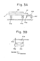
- Fig. 3A is a side elevational view taken along line A of Fig. 2A;
- Fig. 3B is a front elevation view of a dog mounted on the pallet shown in Fig. 3A;
- Fig. 4 is a vertical cross-sectional view of a pallet lifting mechanism;
- Fig. 5 is a fragmentary plan view of a workpiece feeder;
- Figs. 6A through 6E are side elevational views showing progressive steps of workpiece palletizing operation;
- Fig. 7 is a circuit diagram of a sequence control system for controlling the workpiece palletizing operation;
- Fig. 8 is a timing chart for the workpiece palletizing operation;
- Figs. 9A and 9B are side elevational views illustrative of the manner in which a pallet is moved up and down under servo control;
- Fig. 10 is a block diagram of a servo control system for controlling the up-and-down movement of the pallet as shown in Figs. 9A and 98.
- As shown in Fig. 1, a robot system according to the present invention includes a
robot 6 installed on and above amachine tool 1 having a chuck 1a a coupled for corotation with a spindle (not shown), the chuck 1a serving to hold a workpiece as transferred by therobot 6 as will be described later on. Themachine tool 1 also has acover 1b which moves in the direction of the arrow and covers the chuck 1a and other moving parts associated therewith while the workpiece held by the chuck 1a is being machined. - A
rotary workpiece feeder 2 is located adjacent to themachine tool 1 and therobot 6, and is composed of iron frames assembled in the form of a table on which a plurality ofpallets 4 for carrying workpieces thereon are movably supported. Thepallets 4 are drivable by a driver (later described) to travel along a substantially elliptical path on an upper surface of theworkpiece feeder 2, and movable one at a time upwardly by apallet lifting mechanism 5 when thepallets 4 reach a position on theworkpiece feeder 2 in which workpieces are gripped by or released from a workpiece gripper of therobot 6. - The
robot 6 includes arobot body 61 actuatable by an air cylinder (not shown) to move in the axial direction of the spindle of themachine tool 1 or in the direction of a z-axis, agripper arm 62 pivotably supported on therobot body 61, adouble hand 63, awrist 64, and anair cylinder 65 pivotably mounted on therobot body 61. Thedouble hand 63 is composed of a pair of first andsecond grippers second grippers fingers wrist 64 is affixed to a holder plate mounted on a distal end of thearm 62 and is rotatable by the wrist rotating mechanism. Theair cylinder 65 includes a piston rod having a projecting end pivotably coupled to thearm 62 for angularly moving the latter about the pivot thereof. Although not shown, a pair of first and second air tubes is connected respectively to piston-side and rod-side chambers in theair cylinder 65. When air under pressure is supplied through the first air tube into the piston-side chamber, the piston rod extends to turn thearm 62 about its pivot in the direction of the arrowhead A. Conversely, when the rod-side chamber is supplied with air under pressure via the second air tube, the piston rod is retracted to angularly move thearm 62 in the direction of the arrowhead B. - The angular interval which the
arm 62 should travel, and the distance that therobot body 6 should move in the axial direction of the spindle of themachine tool 1, can be determined by limit switches and stops (not illustrated) dependent on the position that thepallet 4 assumes when raised by thepallet lifting mechanism 5 and the position of the chuck 1a. With thearm 62 and therobot body 6 being thus controlled in their motion, workpieces can reliably be attached to or detached from the chuck 1a by thearm 62. - As shown in Figs. 2A through 2C, and Figs. 3A and 3B, each
pallet 4 comprises alower pallet member 41 and anupper pallet member 42 mounted on thelower pallet member 41 for carrying a workpiece thereon. Thelower pallet member 41 has rollers 41a on its four lower corners, a central through opening 41 for passage therethrough of a lifter table 51 of thepallet lifting mechanism 5 for lifting theupper pallet member 42, and three pins 41 (Fig. 2B) spaced around thecentral opening 41b. As illustrated in Figs. 3A and 3B, asupport 41d is screwed to a lower surface of thelower pallet member 41 at an edge thereof and supports adog 41e and achain 41f. Thedog 41e is positioned such that it will engage a pair oflimit switches limit switch 41g serving to enable the pallet driver to be actuated in one direction and thelimit switch 41f to enable the pallet driver to be actuated in the opposite direction. Theupper pallet member 42 has, as shown in Fig. 2C, a first set of three holes 42a in which thepins 41c on thelower pallet 41 are respectively fitted, and a second set of threeholes 42b in which threepins 51a a on the lifter table 51 can respectively be fitted. - When the lifter table 51 is raised in the direction of the arrow as shown in Fig. 2A, the lifter table 51 moves through the central opening 41b in the
lower pallet member 41 until thepins 51a fit respectively into theholes 42b in theupper pallet member 42. Continued upward movement of the lifter table 51 causes theupper pallet member 42 to ascend therewith. When thechain 41f is driven by the pallet driver to move in one or opposite direction perpendicular to the sheet of Fig. 3A, thepallet 4 moves with thechain 41f along the elliptical path on theworkpiece feeder 2. - The
pallet lifting mechanism 5 comprises, as shown in Fig. 4, the lifter table 51 for raising theupper pallet member 42 as described above. The lifter table 51 has on its upper surface thepins 51 a that can fit into theholes 42b in theupper pallet member 42 as shown in Fig. 2A. To a lower surface of the lifter table 51, there are attached fourguide rods 52 at four corners of the lifter table 51 which extend through aframe 21 of theworkpiece feeder 2. Theworkpiece feeder 2 includes an intermediate frame 21' on which there are mountedbearings 53 guiding theguide rods 52 to move therethrough. Lifter bars 54 extend downwardly from the lifter table 51 and have lower ends threaded. Alifter screw 55 threadedly engages the threaded lower ends of the lifter bars 54 and is operatively coupled with amotor 56 through atiming belt 57 and pulleys 58, 58'. When themotor 56 is energized, thelifter screw 55 is rotated about its own axis to cause the lifter bars 54 and hence the lifter table 51 to be lifted or lowered dependent on the direction of rotation of thelifter screw 55. Thus, such vertical movement of the lifter table 51 can move theupper pallet member 42 vertically therewith. Thelifter screw 55 can be braked against rotation by abrake 59 operatively coupled with a lower end thereof. When one of theguide rods 52 is lowered into engagement with alimit switch 60, the latter causes themotor 56 to be de-energized, thus stopping downward movement of the lifter table 51. Thelimit switch 60 therefore serves as a switch for detecting completion of downward movement of the lifter table 51. Themotor 56 may be either an AC motor or a DC motor. - A pair of vertically spaced
sensors 7a, 7b is mounted on anattachment bar 8 secured to theworkpiece feeder 2 and extending in overhanging relation to the lifter table 51. Thesensors 7a, 7b serve to detect an uppermost one ofworkpieces 3 placed on the lifter table 42 as the latter ascends. More specifically, the sensor 7a detects an uppermost unmachined workpiece to de-energize themotor 56 when such unmachined workpieces are to be gripped by therobot 6. Thesensor 7b detects an uppermost machined workpiece to de-energize themotor 56 when such machined workpieces are to be unloaded by therobot 6. - In order for the
robot 6 to grip unmachined workpieces, themotor 56 is driven under a table lifting command from a robot control system (later described) to rotate in one direction to lift theupper pallet member 42, and is turned off in response to detection of an uppermostunmachined workpiece 3 by the sensor 7a. Themotor 56 is then rotated in the opposite direction under a table lowering command from the robot control system after the unmachined workpiece has been held by therobot 6, thereby lowering theupper pallet member 42. Themotor 56 is turned off when theguide rod 52 hits thelimit switch 60, whereupon the downward movement of the lifter table 51 is completed. - When machined workpieces are to be transferred from the
robot 6 onto theupper pallet member 42, themotor 56 is driven under the table lifting command from the robot control system to cause theupper pallet member 42 to ascend. Themotor 56 is turned off when thesensor 7b detects an uppermost machined workpiece. After the machined workpiece has been unloaded from therobot 6, the robot control system issues the table lowering command to drive themotor 56 in the opposite direction for thereby moving theupper pallet member 42 to move downwardly. Themotor 56 is de-energized when thelimit switch 60 is actuated by theguide rod 52 moving downwardly. - As shown in Fig. 5, the
workpiece feeder 2 supports thereon a multiplicity ofpallets workpieces unmachined workpieces attachment bar 8 in overhanging relation to one of the pallets which arrives at the workpiece loading and unloading position that is shown as being taken by thepallet 4c. The pallets havesupports 41d mounted thereon and held in engagement with thechain 41f. When thechain 41f is driven to move along in one direction or the other as shown by the arrows A and B, the pallets move therewith. The limit switches 41 g, 41 are mounted on theworkpiece feeder 2 at a position which thesupport 41 d of thepallet 4e is shown as taking. Thelimit switches support 41d. A desired pallet can be located in the workpiece loading and unloading position by cooperation of thelimit switches dog 41e (Fig. 3B) mounted on thesupport 41d. - Figs. 6A through 6E illustrate successive steps of palletizing operation for unloading a
machine workpiece 3a onto the pallet and picking up anunmachined workpiece 3b from the pallet. The palletizing operation will now be described in detail. After thedouble hand 63 of therobot 6 has been brought to the workpiece loading and unloading position above thepallet 4c (as shown in Fig. 5), the upper pallet member of thepallet 4c on whichunmachined workpieces 3b are placed is raised. When the sensor 7a detects an uppermostunmachined workpiece 3b, the upward movement of the upper pallet member of thepallet 4c is arrested. The uppermostunmachined workpiece 3b is now transferred to thesecond gripper 63b as shown in Fig. 6A. Thefingers 63d of thesecond gripper 63b are closed to grip the uppermostunmachined workpiece 3b. Then, the upper pallet member of thepallet 4c is lowered as illustrated in Fig. 68 until the limit switch 60 (Fig. 4) is actuated by theguide rod 52. During such downward movement of the upper pallet member, the first andsecond grippers wrist 64 so that thefirst gripper 63a will be in a lower position and thesecond gripper 63b in an upper position, as shown in Fig. 6C. - When the upper pallet member of the
pallet 4c has been fully lowered, thechain 41f is moved along in the direction of the arrow A (Fig. 5) under a pallet reversing command from the robot control system until thedog 41e of thepallet 4d acutates thelimit switch 41h (Fig. 5). The movement of thechain 41f is stopped in response to engagement of thedog 41e with thelimit switch 41 h, whereupon thepallet 4b which carriesmachined workpieces 3b thereon is located in the workpiece loading and unloading position. Then, the robot control system issues a pallet lifting command to raise the upper pallet member of thepallet 4b as shown in Fig. 6D until thesensor 7b detects an uppermost one of themachined workpieces 3a. After the upward movement of the upper pallet member of thepallet 4b has been completed, thefingers 63c of thefirst gripper 63a are opened to release a machined workpiece onto the uppermost machinedworkpiece 3a on the upper pallet member of thepallet 4b thus lifted, as illustrated in Fig. 6E. Upon completion of unloading of the machined workpiece from thegripper 63a, the upper pallet member of thepallet 4b is lowered until thelimit switch 60 is actuated. Then, the robot control system issues a pallet feeding command to cause thechain 41f to travel along in the direction of the arrow B (Fig. 5) until thelimit switch 41 g is actuated by thedog 41 e of thepallet 4e. When thelimit switch 41g is actuated, the movement of thechain 41f is arrested to bring thepallets 4a, 4b,... to the position shown in Fig. 5. - At an initial stage of operation of the robot system, all of the pallets except one carry thereon N unmachined workpieces, and the empty pallet is positioned at the location of the
pallet 4b shown in Fig. 5. When N unmachined workpieces on a pallet following the empty pallet have been machined and transferred to the empty pallet according to the operation described above with reference to Figs. 6A through 6E, the next pallet becomes empty until N machined workpieces have been transferred from a succeeding pallet. The pallet which has been emptied each time N unmachined workpieces are machined is moved to the position of thepallet 4b shown in Fig. 5. - Fig. 7 shows a sequence control system for controlling the palletizing operation, and Fig 8 shows timing for the palletizing operation.
- The sequence control system includes a
robot control unit 101, asequence control circuit 102, and apallet driver 103 for moving thechain 41f (Fig. 5) in one direction or the other, thepallet driver 103 including amotor 103a, agearing 103b, and apulley 103c around which thechain 41f extends in driven relation. - The
robot control unit 101 serves as a sequence controller which, while the robot system is in operation, is supplied from thesequence control circuit 102 with a single PUE indicative of completion of upward movement of the upper pallet member of a pallet, a single PDE indicative of completion of downward movement of the upper pallet member, and a signal PPE indicative of completion of locating of the pallet in the workpiece loading and unloading position, and various other signals from therobot 6 and the numerically controlled machine tool. Therobot control unit 101 is responsive to these input signals for issuing a command signal SSC for selecting sensors, a command signal PUC for lifting an upper pallet member, a command signal PDC for lowering an upper pallet member, a command signal PNR for feeding pallets, a command signal PRR for reversing pallets, and a command signal BAC for braking vertical movement of pallets. These command signals are supplied to relays RL1, RL11 through RL15 in thesequence control circuit 102 for actuating the relays. - The relays RL1 through RL5, and relays RL11 through RL15 have contacts r11, r12, normally open and closed contacts r13, r14, r15, and normally open contacts rl11 through rl15, respectively. The
sequence control circuit 102 also includes an AND gate AG, transistors TR1 through TR3 driving the relays RL4, RL3, RL5, respectively, receivers RV1 through RV3, a delay timer switch DTC, a motor drive circuit MRC1 for selectively controlling upward and downward movement of an upper pallet member and for driving themotor 56, and a motor drive circuit MRC2 for selectively controlling feeding and reversing movement of pallets and for driving themotor 103a. - Operation of the sequence control system for the palletizing operation will now be described with reference to Figs. 5, 6A through 6C, 7 and 8.
- When the double hand 63 (Fig. 5) reaches the workpiece loading and unloading position, the
robot control unit 101 issues the command signal PUC for lifting the upper pallet member of thepallet 4c. The relay RL11 is actuated to enable the motor drive circuit MRC, to energize themotor 56 for lifting the upper pallet member of thepallet 4c. When an uppermostunmachined workpiece 3b on the upper pallet member of thepallet 4c as lifted is detected by the sensor 7a, the latter generates a signal WDS indicative of detection of the unmachined workpiece. The signal WDS is supplied via the receiver RV2 to the base of the transistor TR2, which is then turned on to actuate the relay RL3. The relay contact rl3 is actuated to supply the signal PUE to therobot control unit 101, and the motor drive circuit MRC1 stops rotation of themotor 56. Upon generation of the signal PUE, therobot control unit 101 produces the brake signal BAC. Thereafter, therobot control unit 101 generates a signal for closing thefingers 63d in response to the signal PUE thus supplied. After confirming that thefingers 63d have gripped theunmachined workpiece 3b, therobot control unit 101 issues the signal PDC for lowering the upper pallet member of thepallet 4c. The signal PDC causes relay RL12 to be actuated to allow a motor reversing signal to be fed to the motor drive circuit MRC1 for reversing themotor 56. Then, the upper pallet member of thepallet 4c is caused to move downwardly until thelimit switch 60 is actuated by theguide rod 52. When thelimit switch 60 is actuated, it produces the signal DCS which is fed through the receiver RV1 to the base of the transistor TR1, which is then energized. When the transistor TR1 is turned on, the relay contact rl4 is actuated to allow the signal PDE to be supplied to therobot control unit 101, and the motor drive circuit MRC1 stops rotation of themotor 56. While the upper pallet member of thepallet 4c is being lowered, thegrippers wrist 64. - The
robot control unit 101 then issues the signal PRR for reversing pallets in response to the completion of the downward movement of the upper pallet member. The relay RL14 is actuated to supply the motor drive circuit MRC2 with a motor reversing signal to reverse themotor 103a. At the same time, the relay RL2 is actuated to select thelimit switch 41 h for feeding pallets and cause the delay timer switch DTC to start operating. - When one of the pallets is located in the workpiece loading and unloading position as shown in Fig. 5, the
limit switches dog 41 e as illustrated in Fig. 3B. With the pallet feeding command PNR issued at a time t1 (Fig. 8), thechain 41f starts being fed along, and upon elapse of an interval of time Ta thelimit switch 41 h is turned off. Thelimit switch 41 g is thereafter turned off upon elapse of a time interval Tb. Conversely, when the pallet reversing command PRR is issued at a time t2 (Fig. 8), thechain 41f starts being reversed. After the time interval Ta, thelimit switch 41g is turned off, and then thelimit switch 41 h is turned off upon further elapse of the time interval Tb. Time interval Tb is determined by the speed of travel of thechain 41f and the length of thedog 41 e. In order to reverse a pallet into the workpiece loading and unloading position as shown in Fig. 5, it is necessary that thechain 41f be stopped when thelimit switch 41 h is actuated again a time interval (Ta+Tb) after the pallet reversing command signal has been issued. Similarly, when it is necessary to feed a pallet along to the workpiece loading and unloading position, thechain 41f should be stopped when thelimit switch 41g is actuated again the time interval (Ta+Tb) after the pallet feeding command signal has been generated. For the reasons described above, the delay timer switch DTC is set to generate an output of logic level "1" upon elapse of a time interval Tc which is longer than (Ta+Tb) after the pallet feeding command PNR or the pallet reversing command PRR has been issued (after the relays RL13, RL1 have been actuated). - When the
motor 103a is reversed by the pallet reversing command, thechain 41f is moved in the reverse direction. Thelimit switch 41 h issues the signal RDN indicative of completion of the chain reversing movement when thelimit switch 41 h is turned off and then on again. Since the output from the delay timer switch DTC is at a logic level "1" at time, the AND gate AG produces an output of logic level "1" which energizes the transistor TR3 to thereby actuate the relay RL5. As a result, the relay contact r5 is actuated to supply therobot control unit 101 with the positioning completion signal PPE, and simultaneously thechain 41f is stopped. Thus, thepallet 4b on which machined workpieces are placed is now located in the workpiece loading and unloading position. - Upon generation of the signal PPE, the
robot control unit 101 issues the sensor selection signal SSC and the pallet lifting command PUC. The relays RL1, RL11 are actuated to select thesensor 7b and to raise the upper pallet member of thepallet 4b. When thesensor 7b detects an uppermost machined workpiece on the upper pallet member, thesensor 7b generates a signal WDS' indicative of detection of the machined workpiece. Then, the transistor TR2 is turned on to actuate the relay RL3 for generating the signal PUE, whereupon the upward movement of the upper pallet member of thepallet 4b is arrested. Thefingers 63c are opened under a command from therobot control unit 101 to unload a machined workpiece onto a stack of machined workpieces carried on the upper pallet member as lifted. When such an unloading operation has been finished, therobot control unit 101 issues the pallet lowering command PDC to lower the stacked machined workpieces. After the upper pallet member of thepallet 4b has been fully lowered, thepallet 4b is fed along back to the position shown in Fig. 5. The feeding operation of the pallets is basically the same as the reversing operation, and hence will not be described here in detail. - While in the above embodiment the
motor 56 is turned on and off for controlling vertical movement of an upper pallet member under the control of detected signals supplied from thesensors 7a, 7b and thelimit switch 60, the vertical movement of the upper pallet member may instead be controlled by way of positional servo control through computation of the distance that the upper pallet member vertically travels. - Figs. 9A, 9B and 10 are illustrative of such servo control of vertical movement of the upper pallet member. It is now assumed that a maximum number of N unmachined workpieces are placed on each of the pallets, an
upper pallet member 42 with such N unmachined workpieces carried thereon is required to move upwardly the distance Zn (Fig. 9A) until an uppermost workpiece reaches a position in which it can be gripped by the gripper, and anupper pallet member 42 with a single unmachined workpiece carried thereon is required to ascend the distance Z1 until the unmachined workpiece reaches that position. The distance L that an upper pallet member on which m unmachined workpieces (m is larger than N) are placed should travel upwardly or downwardly before reaching .the position in which an uppermost workpiece can be held by the gripper, can then be expressed by the following equation: -

robot control unit 101 and by monitoring the number m of remaining unmachined workpieces on the upper pallet member. With the distance L being determined, the upper pallet member can be positionally controlled by way of pulse distribution control in known NC control. - Fig. 10 shows a servo control system for effecting the above servo control operation. Like or corresponding parts in Fig. 10 are denoted by like or corresponding reference characters in Fig. 4. The servo control system includes a
robot control unit 101 to which the parameters N, Z1 and Zn have already been taught. Therobot control unit 101 includes an arithmetic unit 101a for effecting arithmetic operations based on the equation (1), and apulse distributor circuit 101b b for distributing pulses based on the computed distance L. Aservo control circuit 201 an error circuit 201 a for effecting arithmetic operations on the difference between a distributed pulse Pi and a feedback pulse Fi generated from a pulse coder 56a each time themotor 56 makes a predetermined number of revolutions, and for storing the result of the arithmetic operations, a digital-to- analog converter for converting an error ER supplied from the error circuit 201 a into a corresponding analog signal, and aspeed control circuit 201c. The servo control system also comprises acircuit 202 for monitoring the number of remaining unmachined workpieces, themonitoring circuit 202 including a register 202a in which the maximum number N for unmachined workpieces is set, acounter 202b in which the number N is preset, a one-shot circuit 202c for producing a signal of logic level "1" when servicing by the robot system is finished after a signal SRS has been generated which is indicative of a request for servicing by the robot system, anarithmetic circuit 202d for counting down the count in the counter 202b each time the one-shot circuit produces a signal of logic level "1" and for setting the result in the counter, and a zerodetermination circuit 202e for issuing the result of the arithmetic operation in thearithmetic circuit 202d as the number m of remaining unmachined workpieces and for producing a preset enable signal PSE for presetting in thecounter 202b the number N which has been set in the register 202a when the result of the arithmetic operation is zero. - In operation, the
robot control unit 101 is supplied with the number m of remaining machined workpieces which has been computed by themonitoring circuit 202. When the robot servicing request signal SRS is issued, therobot control unit 101 effects arithmetic operations based on the equation (1) and supplies the result of the arithmetic operations, or a signal indicative of the distance L to thepulse distributor 101b. Thereafter, as with the known NC control positioning procedure, the upper pallet member is lifted, and then is lowered after an uppermost unmachined workpiece is held by the gripper. While the above servo control is described as being applied to the loading of unmachined workpieces, it is also applicable to the unloading of machined workpieces onto the upper pallet member as lifted. - With the arrangement of the present embodiment an industrial robot system does not occupy a large space for installation, is relatively simple in structure, relatively small in size, and less costly to construct.
- In general terms, there is disclosed a robot system for use with a machine tool (1) having a spindle driving a chuck (1a), comprising a robot (6) having a body (61) for being mounted on the machine tool (1), an arm (62) pivotably mounted on the body (61) and rotatable in a plane transverse to an axial direction of the spindle of the machine tool (1), and a hand (63) mounted on a distal end of said arm (62) for gripping a workpiece (3) for transfer to the machine tool (1), and a workpiece feeder (2) is disposed adjacent to the robot (6) and movably supporting a succession of pallets (4) for carrying unmachined and machined workpieces (3) thereon. The workpiece feeder (2) includes a first mechanism for moving the pallets (4) along a path on the workpiece feeder (2) and for positioning the pallets (4) one at a time in a position in which an unmachined workpiece (3) can be picked up from the pallet (4) by the hand (63) or a machined workpiece can be unloaded from the hand (63) onto the pallet (4), and a second mechanism for moving the pallet (4) toward the hand (63) in the position for allowing the hand (63) to pick up the unmachined workpiece and unload the machined workpiece, and for moving the pallet (4) away from the hand (63).
Claims (11)

Applications Claiming Priority (2)
| Application Number | Priority Date | Filing Date | Title |
|---|---|---|---|
| JP56109567A JPS5810481A (en) | 1981-07-14 | 1981-07-14 | Robot system |
| JP109567/81 | 1981-07-14 |
Publications (2)
| Publication Number | Publication Date |
|---|---|
| EP0070196A1 EP0070196A1 (en) | 1983-01-19 |
| EP0070196B1 true EP0070196B1 (en) | 1986-05-28 |
Family
ID=14513510
Family Applications (1)
| Application Number | Title | Priority Date | Filing Date |
|---|---|---|---|
| EP82303690A Expired EP0070196B1 (en) | 1981-07-14 | 1982-07-14 | Robot system |
Country Status (5)
| Country | Link |
|---|---|
| US (1) | US4576537A (en) |
| EP (1) | EP0070196B1 (en) |
| JP (1) | JPS5810481A (en) |
| KR (1) | KR880000539B1 (en) |
| DE (1) | DE3271350D1 (en) |
Families Citing this family (13)
| Publication number | Priority date | Publication date | Assignee | Title |
|---|---|---|---|---|
| FR2547221B1 (en) * | 1983-06-09 | 1987-01-09 | Manurhin | METHOD AND DEVICE FOR LOADING AND UNLOADING PARTS OF A TURNING MACHINE, AND A TURNING MACHINE USING THE SAME |
| JPS6138844A (en) * | 1984-07-31 | 1986-02-24 | Tsubakimoto Chain Co | Work passing device for robot |
| IT1187369B (en) * | 1985-05-10 | 1987-12-23 | Gd Spa | AUTOMATIC ELECTRICITY SOURCE EXCHANGE SYSTEM FOR A MOBILE OPERATING ARM UNIT |
| US4764077A (en) * | 1986-04-18 | 1988-08-16 | Thermwood Corporation | Assembly for performing work functions on a workpiece |
| JPS63180492A (en) * | 1987-01-21 | 1988-07-25 | 三菱電機株式会社 | Industrial robot device |
| JPH024739U (en) * | 1988-06-22 | 1990-01-12 | ||
| US5102280A (en) * | 1989-03-07 | 1992-04-07 | Ade Corporation | Robot prealigner |
| US5181898A (en) * | 1991-09-16 | 1993-01-26 | Cincinnati Milacron, Inc. | Cover assembly for multi-configurable machine tool |
| US5669751A (en) * | 1994-05-09 | 1997-09-23 | Cincinnati Milacron Inc. | Transport system for workpieces |
| US6305500B1 (en) * | 1999-08-25 | 2001-10-23 | Maxtor Corporation | Material delivery system for clean room-like environments |
| ITBO20050557A1 (en) * | 2005-09-13 | 2007-03-14 | Iemca Giuliani Macchine Italia | STACKER WAREHOUSE FOR PIECE LOADING ON A TOOL MACHINE |
| US9725256B1 (en) * | 2016-03-28 | 2017-08-08 | An-Sung Wang | Automatic staged object feeding and discharging system |
| DE102016210508A1 (en) * | 2016-06-14 | 2017-12-14 | Gildemeister Drehmaschinen Gmbh | Handling device for use on a machine tool |
Family Cites Families (7)
| Publication number | Priority date | Publication date | Assignee | Title |
|---|---|---|---|---|
| US3998316A (en) * | 1974-05-10 | 1976-12-21 | Kamm Lawrence J | Manufacturing machine |
| DE2444124C3 (en) * | 1974-09-14 | 1986-04-17 | Index-Werke Kg Hahn & Tessky, 7300 Esslingen | Additional device for the automatic loading and / or unloading of machine tools |
| US4042124A (en) * | 1975-06-02 | 1977-08-16 | Stewart Engineering & Equipment Co. | Pan unstacking and stacking system |
| DE2710661C2 (en) * | 1977-03-11 | 1984-04-12 | Index-Werke Kg Hahn & Tessky, 7300 Esslingen | Device for transporting a workpiece between a workpiece storage and a machine tool |
| WO1981002991A1 (en) * | 1980-04-22 | 1981-10-29 | Ikegai Iron Works Ltd | Flexible loader for machine tool and method of using the same |
| IT1138808B (en) * | 1981-06-23 | 1986-09-17 | Rockwell Rimoldi Spa | PICKING AND POSITIONING DEVICE OF STACKED FABRIC PIECES |
| US4402393A (en) * | 1981-09-25 | 1983-09-06 | Western Electric Company, Incorporated | Conveyor driven fixtures which are precisely positionable at work stations |
-
1981
- 1981-07-14 JP JP56109567A patent/JPS5810481A/en active Pending
-
1982
- 1982-07-13 KR KR8203120A patent/KR880000539B1/en active
- 1982-07-14 EP EP82303690A patent/EP0070196B1/en not_active Expired
- 1982-07-14 DE DE8282303690T patent/DE3271350D1/en not_active Expired
-
1985
- 1985-03-21 US US06/714,345 patent/US4576537A/en not_active Expired - Fee Related
Also Published As
| Publication number | Publication date |
|---|---|
| EP0070196A1 (en) | 1983-01-19 |
| KR880000539B1 (en) | 1988-04-13 |
| DE3271350D1 (en) | 1986-07-03 |
| US4576537A (en) | 1986-03-18 |
| KR840000336A (en) | 1984-02-18 |
| JPS5810481A (en) | 1983-01-21 |
Similar Documents
| Publication | Publication Date | Title |
|---|---|---|
| EP0070196B1 (en) | Robot system | |
| US10873000B2 (en) | Method and automatic production plant for printing on photovoltaic cells | |
| EP0069476B1 (en) | A workpiece feeder | |
| KR100418455B1 (en) | How to process workpieces by robot | |
| JPH07232828A (en) | Parts supply device | |
| US4709605A (en) | Method of working sheet material workpieces by a sheet material working machine tool | |
| SE453370B (en) | DEVICE FOR DISPOSAL OF ASSEMBLY OR WORKING MACHINES WITH THE WORKING PIECE | |
| US6340282B1 (en) | Handling device for feeding and/or removing workpieces | |
| JP2513875B2 (en) | Pallet feeder | |
| GB2301338A (en) | A Handling System for Workpieces | |
| GB2045971A (en) | Control system for an automated press arrangement | |
| CN210306940U (en) | Automatic get material feeding unit and lathe | |
| CA1077387A (en) | Automatic load unload turret punch | |
| JPS6227234A (en) | Method for controlling industrial robot and device therefor | |
| CN210789244U (en) | Full-automatic numerical control lathe | |
| US5149353A (en) | Method for intermittently storing pairs of glass sheets in a windshield production line | |
| EP0102646A1 (en) | Combined shear and punch press | |
| US6192285B1 (en) | Controller for work transfer system | |
| JPH074723B2 (en) | Work transfer device | |
| EP1397301B1 (en) | Feeder device and method of feeding | |
| JPS6263053A (en) | Cubic cnc working apparatus | |
| JP3012606U (en) | Tray changer | |
| CN215547083U (en) | Modular feeding and discharging unit | |
| JPH07241745A (en) | Tray transfer method and transfer control device for tray changer | |
| JPS5940359Y2 (en) | Sheet feeding device |
Legal Events
| Date | Code | Title | Description |
|---|---|---|---|
| PUAI | Public reference made under article 153(3) epc to a published international application that has entered the european phase |
Free format text: ORIGINAL CODE: 0009012 |
|
| AK | Designated contracting states |
Designated state(s): DE FR GB IT |
|
| 17P | Request for examination filed |
Effective date: 19830701 |
|
| GRAA | (expected) grant |
Free format text: ORIGINAL CODE: 0009210 |
|
| AK | Designated contracting states |
Kind code of ref document: B1 Designated state(s): DE FR GB IT |
|
| ITF | It: translation for a ep patent filed |
Owner name: ING. ZINI MARANESI & C. S.R.L. |
|
| REF | Corresponds to: |
Ref document number: 3271350 Country of ref document: DE Date of ref document: 19860703 |
|
| ET | Fr: translation filed | ||
| PLBI | Opposition filed |
Free format text: ORIGINAL CODE: 0009260 |
|
| 26 | Opposition filed |
Opponent name: WABCO WESTINGHOUSE FAHRZEUGBREMSEN GMBH Effective date: 19861206 |
|
| PGFP | Annual fee paid to national office [announced via postgrant information from national office to epo] |
Ref country code: FR Payment date: 19890626 Year of fee payment: 8 |
|
| PGFP | Annual fee paid to national office [announced via postgrant information from national office to epo] |
Ref country code: DE Payment date: 19890717 Year of fee payment: 8 |
|
| ITTA | It: last paid annual fee | ||
| PGFP | Annual fee paid to national office [announced via postgrant information from national office to epo] |
Ref country code: GB Payment date: 19890731 Year of fee payment: 8 |
|
| PG25 | Lapsed in a contracting state [announced via postgrant information from national office to epo] |
Ref country code: GB Effective date: 19900714 |
|
| GBPC | Gb: european patent ceased through non-payment of renewal fee | ||
| RDAG | Patent revoked |
Free format text: ORIGINAL CODE: 0009271 |
|
| STAA | Information on the status of an ep patent application or granted ep patent |
Free format text: STATUS: PATENT REVOKED |
|
| 27W | Patent revoked |
Effective date: 19901129 |
|
| GBPR | Gb: patent revoked under art. 102 of the ep convention designating the uk as contracting state | ||
| REG | Reference to a national code |
Ref country code: FR Ref legal event code: ST |