EP0069826A2 - Device for adjusting and checking a predetermined angular position of a rotating body - Google Patents
Device for adjusting and checking a predetermined angular position of a rotating body Download PDFInfo
- Publication number
- EP0069826A2 EP0069826A2 EP82102591A EP82102591A EP0069826A2 EP 0069826 A2 EP0069826 A2 EP 0069826A2 EP 82102591 A EP82102591 A EP 82102591A EP 82102591 A EP82102591 A EP 82102591A EP 0069826 A2 EP0069826 A2 EP 0069826A2
- Authority
- EP
- European Patent Office
- Prior art keywords
- contact
- encoder
- rotational position
- housing
- mark
- Prior art date
- Legal status (The legal status is an assumption and is not a legal conclusion. Google has not performed a legal analysis and makes no representation as to the accuracy of the status listed.)
- Granted
Links
Images
Classifications
-
- B—PERFORMING OPERATIONS; TRANSPORTING
- B23—MACHINE TOOLS; METAL-WORKING NOT OTHERWISE PROVIDED FOR
- B23Q—DETAILS, COMPONENTS, OR ACCESSORIES FOR MACHINE TOOLS, e.g. ARRANGEMENTS FOR COPYING OR CONTROLLING; MACHINE TOOLS IN GENERAL CHARACTERISED BY THE CONSTRUCTION OF PARTICULAR DETAILS OR COMPONENTS; COMBINATIONS OR ASSOCIATIONS OF METAL-WORKING MACHINES, NOT DIRECTED TO A PARTICULAR RESULT
- B23Q16/00—Equipment for precise positioning of tool or work into particular locations not otherwise provided for
- B23Q16/02—Indexing equipment
- B23Q16/04—Indexing equipment having intermediate members, e.g. pawls, for locking the relatively movable parts in the indexed position
-
- G—PHYSICS
- G01—MEASURING; TESTING
- G01B—MEASURING LENGTH, THICKNESS OR SIMILAR LINEAR DIMENSIONS; MEASURING ANGLES; MEASURING AREAS; MEASURING IRREGULARITIES OF SURFACES OR CONTOURS
- G01B7/00—Measuring arrangements characterised by the use of electric or magnetic techniques
- G01B7/30—Measuring arrangements characterised by the use of electric or magnetic techniques for measuring angles or tapers; for testing the alignment of axes
-
- G—PHYSICS
- G01—MEASURING; TESTING
- G01D—MEASURING NOT SPECIALLY ADAPTED FOR A SPECIFIC VARIABLE; ARRANGEMENTS FOR MEASURING TWO OR MORE VARIABLES NOT COVERED IN A SINGLE OTHER SUBCLASS; TARIFF METERING APPARATUS; MEASURING OR TESTING NOT OTHERWISE PROVIDED FOR
- G01D5/00—Mechanical means for transferring the output of a sensing member; Means for converting the output of a sensing member to another variable where the form or nature of the sensing member does not constrain the means for converting; Transducers not specially adapted for a specific variable
- G01D5/12—Mechanical means for transferring the output of a sensing member; Means for converting the output of a sensing member to another variable where the form or nature of the sensing member does not constrain the means for converting; Transducers not specially adapted for a specific variable using electric or magnetic means
- G01D5/25—Selecting one or more conductors or channels from a plurality of conductors or channels, e.g. by closing contacts
Definitions
- the invention relates to a device according to the generic preamble of the main claim.
- the oldest static measuring method is the so-called "overflow method", by means of which the static delivery start of the injection pump which has already been set with regard to its forward stroke can be sought.
- the pump suction chamber is put under fuel pressure and the camshaft is slowly rotated until the pump piston closes the suction bore during its upward stroke and the fuel stops flowing out.
- a start of delivery marking is made by means of a line mark attached to the housing, which, however, is too imprecise with regard to the tightened exhaust gas regulations and has the serious disadvantage that the line mark marking is not or is very difficult to see from the outside if the pump, for. B. is grown with an end flange on the wheel housing of the internal combustion engine.
- Dynamic measuring methods such as are known or proposed by DE-OS 27 00 878 and German patent application P 29 49 018.4, are more precise, but very complex and expensive in terms of measuring device expenditure, but can be made in the injection pump manufacturer's factory for the first-time setting of the predetermined rotational position the angle encoder mark can be used.
- the object of the invention is now to provide a simple test device by means of which the once set start of delivery position of the drive shaft can be checked without great measuring device wall or, if necessary, can also be set again in the event of a pump repair.
- the device according to the invention with the characterizing features of the main claim has the advantage that a first rough display signal is already available when approaching the predetermined rotational position and then the exact rotational position can be determined in a simple manner by the second contact switch.
- the device according to the invention can be used in combination with a known delivery start signal transmitter in order to bring the mark into the correct position in relation to the housing. If the drive shaft of the injection pump or the rotary body has already been adjusted, it is sufficient to attach the signal transmitter to the associated housing of the rotary body and to turn the drive shaft until the rotational position signal triggered by the second contact switch of the fine display circuit is present.
- both the signal transmitter and the part carrying the angle encoder mark can have the position determined by the production keep, to set the predetermined rotational position, only the angle encoder mark is mounted by an appropriate tool in the position exactly corresponding to the start of conveyance. So that the position of the angle encoder mark that has been held and set cannot be adjusted, it is advantageous that the side walls of the elongated hole are designed in accordance with the characterizing features of claim 10. A very inexpensive installation option results if the device is designed in accordance with the characterizing features of claim 11.
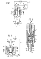
- FIG. 1 shows a simplified representation of the first exemplary embodiment
- FIG. 2 shows a simplified representation of the second exemplary embodiment
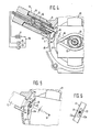
- FIG. 3 shows a practical exemplary embodiment of a signal transmitter that can be used in the second exemplary embodiment
- FIG. 4 shows the third exemplary embodiment with a practical one shown in cross section Embodiment of a signal transmitter that can be used in the first embodiment
- FIG. 5 shows a partial sectional view of the third embodiment with the tool shown for fastening the angle encoder mark
- FIG. 6 shows a partially shown section along the line VI-VI in FIG. 5.
- a drive or camshaft 10 of a fuel injection pump serving as a rotating body and rotating about an axis of rotation D is mounted in an associated housing 11 and is fixedly connected to a part 13 carrying an angle sensor mark 12.
- the part 13 can be a separate component connected to the drive shaft 10 by a conical connection, but it can also be formed by a centrifugal weight carrier of a centrifugal speed governor.
- a signal transmitter 15 with a transmitter housing 16 made of insulating material is inserted in a receiving bore 14 of the housing 11 and connected to a test circuit 18 provided with a battery 17.
- the signal transmitter 15 receives in its transmitter housing 16 a transmitter body 19 which can be displaced radially to the axis of rotation D and which essentially consists of two, one with its own
- M designated center axis insulating layer 21 is electrically separated, but connected by an adhesive body parts 19a and 19b. Both body parts 19a and 19b are connected to the test circuit 18 via electrical connections 22 and 23 and at the same time serve as switching contacts of a first contact switch 24 and a second contact switch 25.
- one body part 19a is provided with a pin-shaped contact part 26, which in the position shown is in contact with a contact tongue 27 of the first contact switch 24.
- This contact switch 24 can, as shown in solid lines, work as a pure touch switch, but it can also, as indicated by a dashed connection .28 to the ground connection of the battery 17, be designed as a limit switch.
- the first contact switch 24 is part of a coarse display circuit 31 provided with a control lamp 29.
- a cross in the lamp 29 indicates that the coarse display circuit 31 is closed by the switch 24 and emits a corresponding warning signal by the switched on control lamp 29.
- the encoder body 19 has been raised against the force of a return spring 32 by the drive shaft 10, which is rotated in the direction of an arrow P, and by the angle encoder mark 12, which is firmly connected to the latter, for actuating the contact switch 24.
- the encoder body 19 is designed as a molded cam 33 on its outer end face facing the angle encoder mark 12.
- the drive shaft 10 or the part 13 provided with the angle encoder 12 continues to rotate in the direction of the arrow in the z. B. indicated in Figure 2, then the angle encoder mark 12 connects the two body parts 19a and 19b now serving as switching contacts of the second contact switch 25, so that a control lamp 35 inserted into a fine display circuit 34 then lights up.
- the two switch contacts 19a and 19b establish a contact bridge with the angular encoder mark 12, thus forming the second contact switch 25 and triggering a rotational position signal which exactly corresponds to the desired or previously set predetermined rotational position Indicates drive shaft 10.
- the second control lamp 35 goes out again and indicates that the angle encoder mark 12 is no longer in the central position.
- the second exemplary embodiment shown in simplified form in FIG. 2, also contains the test circuit 18 provided with the two indicator lights 29 and 35; however, the two display circuits designated 31 'and 34' are operated in a different way.
- the angle encoder mark 12 fastened to the centrifugal weight carrier 13 is connected via a ground connection 41 to the negative pole of the battery 17 and, depending on its respective position, serves as a switching contact or as the ground contact for the two contact switches of the signal transmitter, designated here as 24 'and 25' 15 '.
- the encoder body 19 ' carries on its outer end face 33 facing the angle encoder mark 12 two contact surfaces 19a' and 19b 'which are insulated from one another and from the encoder body 19' and which, depending on the direction of rotation of the part 13, have the respective other switching contact of the first and second contact switches 24 'and 25 ' form.
- Angle encoder mark 12 firstly forms the contact surface 19a 'and forms the first contact switch 24' inserted into the rough display circuit 31 '. If the angle encoder mark 12 reaches the center position shown, then it also establishes a connection to the second contact surface 19b 'and forms together with this the second contact switch 25' inserted in the fine display circuit 34 '. In the center position shown, both indicator lights 29 and 35 light up, which indicates the exact center position.
- the display circuit 34 ' would act as a coarse display circuit and the display circuit 31' as a fine display circuit and the switch 25 'as the first and the switch 24' as the second contact switch.
- the circuit shown in FIG. 2 thus also shows the respective direction of rotation with the indicator lamp which lights up first, with which the angle encoder mark 12 approaches the central position to be measured.
- the practical exemplary embodiment shown in section in FIG. 3 of the signal transmitter 15 ′′ which can be used in FIG. 2 contains in its transmitter housing 16 made of insulating material a transmitter body which, like in the first exemplary embodiment, is produced from two body parts 19a and 19b by means of an interposed insulating layer 21 and therefore also how 1 in Fig. 1.
- the connections to the test circuit 18 are made as in Fig. 2.
- the signal transmitter 15 "contains a sliding contact 41a, which establishes the ground connection from the battery 17 to the angle encoder mark 12 via a metal knurled screw 41b (see Figure 2).
- a fixing pin 42 fastened in the encoder housing 16 serves both to secure the rotational position of the encoder body 19 relative to the housing 16 and to secure the rotational position of the encoder housing 16 compared to the receiving hole not shown here in the associated housing.
- the lines which are led out of the interior of the signal transmitter 15 "and connected to the switch contacts 19a and 19b are designated 31 'and 34' for simplicity, since they are to be regarded as parts of these two display circuits.
- the signal transmitter 15 provided with the test circuit 18 is inserted into the housing 11 of a centrifugal speed controller 45 by the fixing pin 42 in a rotationally secured manner.
- the signal transmitter 15 shown in longitudinal section corresponds in structure and function to the signal transmitter 15 described in FIG. 1 and carries within the transmitter housing 16 the first contact switch 24 fastened to the housing 16 on an insulating material plate 46.
- FIGS 12 ' from a tab of a sheet metal bracket 48 protruding at right angles from the surface of a sheet metal capsule 47 and riveted to a wall part 47a of this sheet metal capsule 47 by means of a blind rivet 49.
- the sheet metal capsule 47 is part of a centrifugal weight assembly 51 of the speed controller 45, which is attached to an injection pump (not shown in more detail), is fastened in a rotationally fixed manner to this assembly 51 and is connected in a rotationally fixed manner therewith to the drive shaft 10 serving as a rotating body. So that the angle encoder mark 12 'on the sheet metal angle 48 in an exact, z. B. the start of conveyance corresponding rotary position can be attached to the sheet metal capsule 47, the latter is provided with an elongated hole 52 which extends in the circumferential direction of the sheet metal capsule 47 and to better secure the position of the blind rivet 49 and thus the sheet metal angle 48 on its side walls 52a with a finely toothed surface is provided (see Figure 6).
- the test circuit 18 also shines here when the encoder body is exactly in the central position 19 standing angle encoder mark 12 'both control lamps 29 and 35 at the same time.
- 12 'to the drive shaft 10 can either adjust the angle encoder mark 12, 12' itself relative to the drive shaft 10 to compensate for the existing angular deviation, as has been described for FIGS. 4 to 6, or the installation position of the housing 16 can be changed in which 2, is inserted into the correspondingly larger receiving bore 14 of the housing 11 via an eccentric receiving bush 55.
- This receiving bush 55 is slotted on one side for receiving the fixing pin 42, and the slot designated 55a also serves to fix the position of the Receiving sleeve 55 in the housing 11, which for this purpose with a projecting Nose 56 is provided.
- the battery 17 serving as the power supply source can. either be formed by the battery supplying the motor with power, or it can also be formed by a special battery which is accommodated together with the signal generator 15, 15 'and the test circuit 18 in a common housing and can be handled in the same way as a test lamp .
- a special battery which is accommodated together with the signal generator 15, 15 'and the test circuit 18 in a common housing and can be handled in the same way as a test lamp .
- light-emitting diodes or other warning and display devices can also be used.
Abstract
Ein in einem Gehäuse (11) der Einrichtung gelagerter Rotationskörper (10) trägt eine Winkelgebermarke (12) die als Signalauslöser eines zum Gehäuse (11) lagefixiert befestigten Signalgebers (15) dient. Der Signalgeber (15) weist einen in seinem Gebergehäuse (16) axial verschiebbaren Geberkörper (19) auf, der zur Betätigung eines ersten Kontaktschalters (24) in Richtung seiner Längsachse verschiebbar ist, und der innerhalb seiner äußeren Stirnfläche (33) mit einem mit der Winkelgebermarke (12) zusammenwirkenden Schaltkontakt (19b) eines zweiten Kontaktschalters (25) versehen ist. Nach Betätigen beider Kontaktschalter (24 und 25) steht die Winkelgebermarke (12) in einer vorbestimmten Drehlage, die in der dazugehörigen Prüfschaltung (18) angezeigt wird und insbesondere zur Ermittlung der Förderbeginnstellung der Antriebswelle (10) einer Kraftstoffeinspritzpumpe für Brennkranmaschinen dient.A rotary body (10) mounted in a housing (11) of the device carries an angle indicator mark (12) which serves as a signal trigger of a signal transmitter (15) fixed in position relative to the housing (11). The signal transmitter (15) has a transmitter body (19) which is axially displaceable in its transmitter housing (16) and which can be displaced in the direction of its longitudinal axis in order to actuate a first contact switch (24) and which within its outer end face (33) is connected to the one Angle encoder mark (12) cooperating switch contact (19b) of a second contact switch (25) is provided. After actuating both contact switches (24 and 25), the angle encoder mark (12) is in a predetermined rotational position, which is displayed in the associated test circuit (18) and is used in particular to determine the start of delivery position of the drive shaft (10) of a fuel injection pump for internal combustion engine cranes.
Description
Die Erfindung geht aus von einer Einrichtung nach dem gattungsbildenden Oberbegriff des Hauptanspruchs.The invention relates to a device according to the generic preamble of the main claim.
Zum Einstellen, Überprüfen und Wiederauffinden einer vorbestimmten Drehlage eines Rotationskörpers ist erforderlich, die Drehlage einer fest mit dem Rotationskörper verbundenen Winkelgebermarke genau einstellen zu können oder nach der Einstellung im Bezug zum Gehäuse des Rotationskörpers genau messen zu können. So ist es insbesondere bei Kraftstoffeinspritzpumpen notwendig, die Förderbeginnstellung oder eine dem Förderbeginn entsprechende Drehlage des - vom Antrieb aus gesehen - dem ersten Pumpenauslaß zugeordneten Nockens der hier den Rotationskörper bzw. die Antriebswelle darstellenden Nockenwelle zu messen und danach die Nockenwelle festzuhalten, um die Einspritzpumpe an die entsprechend vorbereitete Brennkraftmaschine anbauen zu können. Um nun die Förderbeginnstellung der Nockenwelle erstmals einstellen zu können, sind verschiedene statische und auch dynamische Meßverfahren bekannt. Das älteste statische Meßverfahren ist die sogenannte "Überlaufmethode", durch die der statische Förderbeginn der bezüglich ihres Vorhubs bereits eingestellten Einspritzpumpe gesucht werden kann. Der Pumpensaugraum wird unter Kraftstoffdruck gesetzt und die Nockenwelle langsam soweit verdreht, bis der Pumpenkolben bei seinem Aufwärtshub die Saugbohrung verschließt und der Kraftstoff aufhört auszufließen. In dieser Drehlage wird eine Förderbeginnmarkierung mittels einer am Gehäuse angebrachten Strichmarke vorgenommen, die jedoch bezüglich der verschärften Abgasbestimmungen zu ungenau ist und den schwerwiegenden Nachteil hat, daß die Strichmarkenmarkierung von außen nicht oder sehr schwer einzusehen ist, wenn die Pumpe z. B. mit einem Stirnflansch an den Räderkasten der Brennkraftmaschine angebaut wird.In order to set, check and find a predetermined rotational position of a rotary body, it is necessary to be able to precisely set the rotational position of an angular encoder mark firmly connected to the rotary body, or to be able to measure precisely after the adjustment in relation to the housing of the rotary body. For fuel injection pumps, in particular, it is necessary to measure the start of delivery position or a rotational position of the cam of the camshaft which represents the first pump outlet, as seen from the drive, and then to hold the camshaft in order to start the injection pump to be able to install the correspondingly prepared internal combustion engine. To start the delivery of the camshaft for the first time Different static and dynamic measuring methods are known. The oldest static measuring method is the so-called "overflow method", by means of which the static delivery start of the injection pump which has already been set with regard to its forward stroke can be sought. The pump suction chamber is put under fuel pressure and the camshaft is slowly rotated until the pump piston closes the suction bore during its upward stroke and the fuel stops flowing out. In this rotational position, a start of delivery marking is made by means of a line mark attached to the housing, which, however, is too imprecise with regard to the tightened exhaust gas regulations and has the serious disadvantage that the line mark marking is not or is very difficult to see from the outside if the pump, for. B. is grown with an end flange on the wheel housing of the internal combustion engine.
Dynamische Meßverfahren, wie sie durch die DE-OS 27 00 878 und die deutsche Patentanmeldung P 29 49 018.4 bekannt geworden bzw. vorgeschlagen sind, sind genauer, allerdings bezüglich des Meßgeräteaufwandes sehr aufwendig und teuer, können jedoch im Einspritzpumpenherstellerwerk zum erstmaligen Einstellen der vorbestimmten Drehlage der Winkelgebermarke herangezogen werden.Dynamic measuring methods, such as are known or proposed by DE-OS 27 00 878 and German
Die Aufgabe der Erfindung besteht nun darin, eine einfache Prüfeinrichtung bereitzustellen, mittels der ohne großen Meßgeräteaafwand die einmal eingestellte Förderbeginnstellung der Antriebswelle überprüft oder gegebenenfalls im Falle einer Pumpenreparatur auch wieder eingestellt werden kann.The object of the invention is now to provide a simple test device by means of which the once set start of delivery position of the drive shaft can be checked without great measuring device wall or, if necessary, can also be set again in the event of a pump repair.
Die erfindungsgemäße Einrichtung mit den kennzeichnenden Merkmalen des Hauptanspruchs hat den Vorteil, daß bereits bei Annäherung an die vorbestimmte Drehlage ein erstes Grobanzeigesignal vorhanden ist und danach durch den zweiten Kontaktschalter auf einfache Weise die exakte Drehlagenstellung festgestellt werden kann. Zum erstmaligen Einstellen der vorbestimmten Drehlage kann die erfindungsgemäße Einrichtung in Kombination mit einem bekannten Förderbeginnsignalgeber verwendet werden, um die Marke in bezug auf das Gehäuse in die richtige Lage zu bringen. Ist die Antriebswelle der Einspritzpumpe bzw. der Rotationskörper bereits eingestellt worden, dann genügt es, den Signalgeber am zugehörigen Gehäuse des Rotationskörpers zu befestigen und die Antriebswelle so lange zu drehen, bis das vom zweiten Kontaktschalter des Feinanzeigeschaltkreises ausgelöste Drehlagensignal vorhanden ist.The device according to the invention with the characterizing features of the main claim has the advantage that a first rough display signal is already available when approaching the predetermined rotational position and then the exact rotational position can be determined in a simple manner by the second contact switch. To set the predetermined rotational position for the first time, the device according to the invention can be used in combination with a known delivery start signal transmitter in order to bring the mark into the correct position in relation to the housing. If the drive shaft of the injection pump or the rotary body has already been adjusted, it is sufficient to attach the signal transmitter to the associated housing of the rotary body and to turn the drive shaft until the rotational position signal triggered by the second contact switch of the fine display circuit is present.
Durch die in den Unteransprüchen und auch im Nebenanspruch 9 aufgeführten Merkmale sind vorteihafte Ausgestaltungen, Weiterbildungen und Verbesserungen der im Hauptanspruch angegebenen Einrichtung möglich. So wird durch die kennzeichnenden Merkmale des Anspruchs 2 eine einfache Herstellung des Geberkörpers und einwandfreie Isolierung gegenüber dem Gehäuse erreicht. Bei einem gemäß Anspruch 3 ausgebildeten Ausführungsbeispiel ist es möglich, den gesamten Geberkörper aus Isolierstoff herzustellen, und bei einer Ausgestaltung der Einrichtung nach Anspruch 4 ist es möglich, die Einrichtung mit einer separaten Betriebsspannungsquelle, z. B. Trockenbatterien, auszustatten, so daß die gesamte Einrichtung wie eine einfache Prüflampe zu handhaben ist.Advantageous refinements, developments and improvements of the device specified in the main claim are possible due to the features listed in the subclaims and also in subsidiary claim 9. Thus, a simple manufacture of the encoder body and flawless insulation with respect to the housing is achieved by the characterizing features of claim 2. In an embodiment designed according to claim 3, it is possible to manufacture the entire encoder body from insulating material, and in an embodiment of the device according to claim 4, it is possible to use a separate operating voltage source, for. B. dry cell batteries, so that the entire device can be handled like a simple test lamp.
Bei einer gemäß den Ansprüchen 6 oder 7 ausgestalteten Einrichtung kann diese an das Bordnetz oder auch an eine separate Betriebsspannungsquelle angeschlossen werden, außerdem ist eine sichere Funktion gewährleistet.In the case of a device designed according to claims 6 or 7, it can be connected to the vehicle electrical system or to a separate operating voltage source, and a safe function is also guaranteed.
Bei einer gemäß den Merkmalen des Anspruchs 9 ausgestalteten Einrichtung, die insbesondere in Verbindung mit den Merkmalen des Anspruchs 1 zur Ermittlung der Förderbeginnstellung der Antriebswelle einer Kraftstoffeinspritzpumpe herangezogen werden kann, können sowohl der Signalgeber als auch das die Winkelgebermarke tragende Teil die durch die Fertigung festgelegte Lage behalten, zur Einstellung der vorbestimmten Drehlage wird lediglich die Winkelgebermarke durch ein entsprechendes Werkzeug in die genau dem Förderbeginn entsprechende Lage montiert. Damit die einmal festgehaltene und eingestellte Lage der Winkelgebermarke sich nicht verstellen kann, ist es vorteilhaft, daß die Seitenwände des Langlochs gemäß den kennzeichnenden Merkmalen des Anspruchs 10 ausgestaltet sind. Eine sehr günstige Montagemöglichkeit ergibt sich, wenn die Einrichtung gemäß den kennzeichnenden Merkmalen des Anspruchs 11 ausgestaltet ist.In the case of a device designed according to the features of claim 9, which can be used in particular in conjunction with the features of claim 1 to determine the start of delivery position of the drive shaft of a fuel injection pump, both the signal transmitter and the part carrying the angle encoder mark can have the position determined by the production keep, to set the predetermined rotational position, only the angle encoder mark is mounted by an appropriate tool in the position exactly corresponding to the start of conveyance. So that the position of the angle encoder mark that has been held and set cannot be adjusted, it is advantageous that the side walls of the elongated hole are designed in accordance with the characterizing features of
Drei Ausführungsbeispiele der erfindungsgemäßen Einrichtung werden nachstehend anhand der Zeichnung näher beschrieben. Es zeigen Figur 1 eine vereinfachte Darstellung des ersten Ausführungsbeispiels, Figur 2 eine vereinfachte Darstellung des zweiten Ausführungsbeispiels, Figur 3 ein praktisches Ausführungsbeispiel eines beim zweiten Ausführungsbeispiel verwendbaren Signalgebers, Figur 4 das dritte Ausführungsbeispiel mit einem im Querschnitt dargestellten praktischen Ausführungsbeispiel eines beim ersten Ausführungsbeispiel verwendbaren Signalgebers, Figur 5 eine Teilschnittdarstellung zum dritten Ausführungsbeispiel mit eingezeichnetem Werkzeug zur Befestigung der Winkelgebermarke und Figur 6 einen teilweise dargestellten Schnitt längs der Linie VI - VI in Figur 5.Three embodiments of the device according to the invention are described below with reference to the drawing. FIG. 1 shows a simplified representation of the first exemplary embodiment, FIG. 2 shows a simplified representation of the second exemplary embodiment, FIG. 3 shows a practical exemplary embodiment of a signal transmitter that can be used in the second exemplary embodiment, and FIG. 4 shows the third exemplary embodiment with a practical one shown in cross section Embodiment of a signal transmitter that can be used in the first embodiment, FIG. 5 shows a partial sectional view of the third embodiment with the tool shown for fastening the angle encoder mark, and FIG. 6 shows a partially shown section along the line VI-VI in FIG. 5.
Obwohl die erfindungsgemäße Einrichtung zum Ermitteln einer vorbestimmten Drehlage eines beliebigen Rotationskörpers, z. B. auch eines Werkzeugdrehtisches, verwendet werden kann, sind in den nachfolgend beschriebenen Ausführungsbeispielen ausschließlich Einrichtungen zum Ermitteln der Förderbeginnstellung der Antriebswelle von Kraftstoffeinspritzpumpen beschrieben.Although the device according to the invention for determining a predetermined rotational position of any rotational body, for. B. also a tool turntable can be used, only devices for determining the start of delivery position of the drive shaft of fuel injection pumps are described in the embodiments described below.
So ist bei dem in Figur 1 vereinfacht dargestellten ersten Ausführungsbeispiel eine als Rotationskörper dienende, sich um eine Drehachse D drehende Antriebs- oder Nockenwelle 10 einer nicht näher dargestellten Kraftstoffeinspritzpumpe in einem zugehörigen Gehäuse 11 gelagert und fest mit einem eine Winkelgebermarke 12 tragenden Teil 13 verbunden. Das Teil 13 kann ein gesondertes, mit der Antriebswelle 10 durch eine Konusverbindung verbundenes Bauteil sein, es kann jedoch auch von einem Fliehgewichtsträger eines Fliehkraftdrehzahlreglers gebildet sein. In einer Aufnahmebohrung 14 des Gehäuses 11 ist ein Signalgeber 15 mit einem aus Isolierstoff gefertigten Gebergehäuse 16 eingesetzt und an eine mit einer Batterie 17 versehene Prüfschaltung 18 angeschlossen.In the first exemplary embodiment, shown in simplified form in FIG. 1, a drive or
Der Signalgeber 15 nimmt in seinem Gebergehäuse 16 einen radial zur Drehachse D verschiebbaren Geberkörper 19 auf, der im wesentlichen aus zwei, durch eine durch seine mitThe
M bezeichnete Mittelachse gehende Isolierschicht 21 elektrisch getrennten, jedoch durch ein Klebmittel verbundenen Körperteilen 19a und 19b besteht. Beide Körperteile 19a und 19b sind über elektrische Anschlüsse 22 und 23 an die Prüfschaltung 18 angeschlossen und dienen zugleich als Schaltkontakte eines ersten Kontaktschalters 24 und eines zweiten Kontaktschalters 25. Dazu ist das eine Körperteil 19a mit einem stiftförmigen Kontaktteil 26 versehen, der in der gezeichneten Stellung mit einer Kontaktzunge 27 des ersten Kontaktschalters 24 in Berühung steht. Dieser Kontaktschalter 24 kann, wie ausgezogen dargestellt, als reiner Berührungsschalter arbeiten, er kann jedoch auch, wie durch eine gestrichelte Verbindung .28 zum Masseanschluß der Batterie 17 angedeutet, als ein Endschalter ausgebildet sein.M designated center
Der erste Kontaktschalter 24 ist ein Teil eines mit einer Kontrolleuchte 29 versehenen Grobanzeigeschaltkreises 31. Durch ein Kreuz in der Leuchte 29 ist angedeutet, daß durch den Schalter 24 der Grobanzeigeschaltkreis 31 geschlossen ist und durch die eingeschaltete Kontrolleuchte 29 ein entsprechendes Vorsignal abgibt. In der dargestellten Stellung des Geberkörpers 19 ist dieser durch die in Richtung eines Pfeiles P verdrehte Antriebswelle 10 und durch die mit dieser fest verbundene Winkelgebermarke 12 zur Betätigung des Kontaktschalters 24 entgegen der Kraft einer Rückstellfeder 32 angehoben worden. Um diese Hubbewegung zuerzeugen, ist der Geberkörper 19 an seiner äußeren, der Winkelgebermarke 12 zugewandten Stirnfläche als ein Formnocken 33 ausgebildet. Dreht sich die Antriebswelle 10 bzw. das mit dem Winkelgeber 12 versehenen Teil 13 weiter in Pfeilrichtung in die z. B. in Figur 2 angedeutete Mittellage, dann verbindet die Winkelgebermarke 12 die beiden jetzt als Schaltkontakte des zweiten Kontaktschalters 25 dienenden Körperteile 19a und 19b, so daß dann eine in einen Feinanzeigeschaltkreis 34 eingefügte Kontrolleuchte 35 aufleuchtet.The
Bei in Verlängerung der Mittelachse M des Geberkörpers 19 stehender Winkelgebermarke 12 stellen die beiden Schaltkontakte 19a und 19b mit der Winkelgebermarke 12 eine Kontaktbrücke her, bilden damit den zweiten Kontaktschalter 25 und lösen ein Drehlagensignal aus, das exakt die gesuchte bzw. vorher eingestellte vorbestimmte Drehlage der Antriebswelle 10 anzeigt. Sobald sich die Winkelgebermarke 12 aus der Mittellage wegbewegt, erlischt die zweite Kontrolleuchte 35 wieder und zeigt an, daß die Winkelgebermarke 12 nicht mehr in der Mittellage steht.When the
Bei den nachfolgenden Ausführungsbeispielen sind gleiche oder gleichwirkende Teile gleich bezeichnet, stark abweichende Teile mit einem Indexstrich versehen und neue Teile neu bezeichnet.In the following exemplary embodiments, parts that are the same or have the same effect are identified in the same way, parts that differ greatly are provided with an index line and new parts are designated again.
Das zweite, in Figur 2 vereinfacht dargestellte Ausführungsbeispiel enthält ebenfalls die mit den zwei Kontrolleuchten 29 und 35 versehene Prüfschaltung 18; die beiden mit 31' und 34' bezeichneten Anzeigeschaltkreise sind jedoch in abweichender Weise betätigt. Die an dem Fliehgewichtsträger 13 befestigte Winkelgebermarke 12 ist über einen Masseanschluß 41 mit dem Minuspol der Batterie 17 verbunden und dient je nach seiner jeweiligen Stellung als ein Schaltkontakt bzw. als der Massekontakt für die beiden hier mit 24' und 25' bezeichneten Kontaktschalter.des Signalgebers 15'. Der Geberkörper 19' trägt an seiner der Winkelgebermarke 12 zugewandten äußeren Stirnfläche 33 zwei gegeneinander und zum Geberkörper 19' isolierte Kontaktflächen 19a' und 19b', die je nach der Drehrichtung des Teiles 13 den jeweils anderen Schaltkontakt des ersten und zweiten Kontaktschalters 24' und 25' bilden.The second exemplary embodiment, shown in simplified form in FIG. 2, also contains the
Dreht sich das die Winkelgebermarke 12 tragende Teil 13 in die entsprechend dem eingezeichneten Pfeil P angegebene Drehrichtung, so berührt die als Schaltkontakt dienende Winkelgebermarke 12 zuerst die Kontaktfläche 19a' und bildet mit dieser den ersten, in den Grobanzeigeschaltkreis 31' eingefügten Kontaktschalter 24'. Gelangt die Winkelgebermarke 12 in die gezeichnete Mittellage, dann stellt sie auch eine Verbindung zu der zweiten Kontaktfläche 19b' her und bildet mit dieser zusammen den in den Feinanzeigeschaltkreis 34' eingefügten zweiten Kontaktschalter 25'. In der gezeichneten Mittellage leuchten beide Kontrollleuchten 29 und 35 auf, wodurch die exakte Mittellage angezeigt wird. Bei entgegen der Pfeilrichtung stattfindender Drehung des Teiles 13 würde der Anzeigeschaltkreis 34' als Grobanzeigeschaltkreis und der Anzeigeschaltkreis 31' als Feinanzeigeschaltkreis und der Schalter 25' als erster und der Schalter 24' als zweiter Kontaktschalter wirken. Die in Figur 2 dargestellte Schaltung zeigt also auch durch die zuerst aufleuchtende Kontrollleuchte die jeweilige Drehrichtung an, mit der die Winkelgebermarke 12 sich der zu messenden Mittellage nähert.If the
Das in Figur 3 im Schnitt dargestellte praktische Ausführungsbeispiel des in Figur 2 verwendbaren Signalgebers 15" enthält in seinem aus Isolierstoff bestehenden Gebergehäuse 16 einen Geberkörper, der wie beim ersten Ausführungsbeispiel aus zwei Körperteilen 19a und 19b mittels einer zwischengelegten Isolierschicht 21 hergestellt ist und deshalb auch wie in Figur 1 mit 19 bezeichnet ist. Die Anschlüsse an die Prüfschaltung 18 erfolgen wie bei Figur 2. Als Teil des Masseanschlusses 41 enthält der Signalgeber 15" einen Schleifkontakt 41a, der über eine metallene Rändelschraube 41b die Masseverbindung von der Batterie 17 zur Winkelgebermarke 12 herstellt (siehe dazu Figur 2). Ein im Gebergehäuse 16 befestigter Fixierstift 42 dient sowohl der Drehlagensicherung des Geberkörpers 19 zum Gehäuse 16 als auch der Drehlagensicherung des Gebergehäuses 16 gegenüber der hier nicht näher dargestellten Aufnahmebohrung im zugehörigen Gehäuse. Die aus dem Inneren des Signalgebers 15" herausgeführten und mit den Schaltkontakten 19a und 19b verbundenen Leitungen sind zur Vereinfachung mit 31' und 34' bezeichnet, da sie als Teile dieser beiden Anzeigeschaltkreise anzusehen sind.The practical exemplary embodiment shown in section in FIG. 3 of the
Beim dritten, in Figur 4 dargestellten Ausführungsbeispiel ist der mit der Prüfschaltung 18 versehene Signalgeber 15 durch den Fixierstift 42 drehlagengesichert in das Gehäuse 11 eines Fliehkraftdrehzahlreglers 45 eingesetzt. Der im Längsschnitt dargestellte Signalgeber 15 entspricht in Aufbau und Funktion dem zu Figur 1 beschriebenen Signalgeber 15 und trägt innerhalb des Gebergehäuses 16 den auf einer Isolierstoffplatte 46 am Gehäuse 16 befestigten ersten Kontaktschalter 24. Bei diesem in den Figuren 4 bis 6 dargestellten Ausführungsbeispiel besteht die Winkelgebermarke 12' aus einem über die Oberfläche einer Blechkapsel 47 herausragenden, rechtwinklig abgebogenen Lappen eines Blechwinkels 48 der auf einen Wandteil 47a dieser Blechkapsel 47 mittels eines Blindniets 49 aufgenietet ist. Die Blechkapsel 47 ist ein Teil einer Fliehgewichtsbaugruppe 51 des an eine nicht näher dargestellte Einspritzpumpe angebauten Drehzahlreglers 45, an dieser Baugruppe 51 drehfest befestigt und über diese mit der als Rotationskörper dienenden Antriebswelle 10 drehfest verbunden. Damit die Winkelgebermarke 12' am Blechwinkel 48 in eine genaue, z. B. dem Förderbeginn entsprechende Drehlage an der Blechkapsel 47 befestigt werden kann, ist letztere mit einem Langloch 52 versehen, das sich in Umfangsrichtung der Blechkapsel 47 erstreckt und zur besseren Lagesicherung des Blindniets 49 und damit des Blechwinkels 48 an seinen Seitenwänden 52a mit einer feingezahnten Oberfläche versehen ist (siehe dazu Figur 6).In the third exemplary embodiment shown in FIG. 4, the
Zur Befestigung des Blechwinkels 48 dient ein in Figur 5 gestrichelt angedeutetes Nietwerkzeug 53, mit dem der Blindniet 49 bei zuvor um den Winkel α in Figur 4 aus der Mittelachse M im Uhrzeigersinn verdrehter Antriebswelle 10 befestigt wird. Der Winkel α entspricht genau dem Abstand zwischen der Mitte der Winkelgebermarke 12' und einer zugehörigen nicht näher bezeichneten, den Blindniet 49 aufnehmenden Bohrung im Blechwinkel 48. Wie bereits zu Figur 1 beschrieben, leuchten auch hier in der Prüfschaltung 18 bei genau in Mittellage des Geberkörpers 19 stehender Winkelgebermarke 12' beide Kontrolleuchten 29-und 35 zugleich auf.5 is used to fasten the
Zur Bestimmung der vorbestimmten, z. B. dem Förderbeginn eines ersten Pumpenauslasses zugeordneten Drehlage der Winkelgebermarke 12 bzw. 12' dienen bei allen Ausführungsbeispielen die in das Gehäuse 11 eingesetzten Signalgeber 15 bzw. 15' oder 15 " mit der dazugehörigen Prüfschaltung 18. Beim erstmaligen Einstellen der Lage der Winkelgebermarke 12, 12' zur Antriebswelle 10 kann zum Ausgleich der vorhandenen Winkelabweichung entweder die Winkelgebermarke 12, 12' selber relativ zur Antriebswelle 10 verstellt werden, wie dies zu den Figuren 4 bis 6 beschrieben wurde, oder es kann die Einbaulage des Gehäuses 16 verändert werden, in dem dieses, wie in Figur 2 angedeutet, über eine exzentrische Aufnahmebüchse 55 in die entsprechend größere Aufnahmebohrung 14 des Gehäuses 11 eingesetzt wird. Diese Aufnahmebüchse 55 ist auf einer Seite zur Aufnahme des Fixierstiftes 42 geschlitzt, und der mit 55a bezeichnete Schlitz dient auch zur Lagefixierung der Aufnahmebüchse 55 im Gehäuse 11, welches zu diesem Zweck mit einer vorspringenden Nase 56 versehen ist.To determine the predetermined, e.g. B. the start of delivery of a first pump outlet assigned rotational position of the
Die einfachste Möglichkeit, die Lage des Signalgebers 15, z. B. bei dem in Figur 1 dargestellten Beispiel,mit der vorbestimmten Winkellage der Antriebswelle 10 beiimittig stehender Winkelgebermarke 12 in Einklang zu bringen, besteht darin, das die Winkelgebermarke 12 tragende Teil 13 relativ zur Antriebswelle 10 zu verdrehen, was auf die einfachste Weise durch Lösen einer Konusverbindung 57 zwischen den beiden Teilen 10, 13 und danach erfolgendem Anziehen dieser Verbindung bei entsprechend ausgerichteten Teilen erfolgen kann. Dazu werden das Teil 13 und die Antriebswelle 10 ohne die sonst übliche Keilverbindung ausgeführt.The easiest way, the location of the
Obwohl die wesentlichen Funktionen bereits zu den Ausführungsbeispielen beschrieben sind, wird nachfolgend ein Prüfarbeitsgang zum Auffinden der bereits eingestellten vorbestimmten Drehlage der Antriebswelle 10 anhand der Figuren 1 und 2 kurz erläutert:
- Bei der vorher bezüglich der vorbestimmten Drehlage der Winkelgebermarke 12 eingestellten Einspritzpumpe wird der
mit der Prüfschaltung 18verbundene Signalgeber 15 indie Aufnahmebohrung 14 des Gehäuses 11 eingesetzt und dieAntriebswelle 10 im Uhrzeigersinn, in Richtung des Pfeiles P,solange verdreht, bis zuerst bei Annäherung an die Mittellage dieKontrolleuchte 29 des Grobanzeigeschaltkreises 31 aufleuchtet. Jetzt wird dieNockenwelle 10 langsam weitergedreht, bis auch diezweite Kontrolleuchte 35 des Feinanzeigeschaltkreises 34 aufleuchtet, wie dies bei dem in Figur 2 dargestellten Ausführungsbeispiel der Fall ist.Würde die Antriebswelle 10 auch nur geringfügig über die vorbestimmte Drehlage hinaus weitergedreht, dann würde sofort dieKontrolleuchte 35 wieder erlöschen, da der Kontakt zwischenden Schaltkontakten 19a und 19b bzw. 19a' und 19b' unterbrochen würde. Unabhängig davon, ob wie beim ersten Ausführungsbeispiel nach Figur 1 und dem dritten Ausführungsbeispiel nach Figur 4 der Masseanschluß der Batterie 17 über einen Schaltkontakt des Geberkörpers 19 erfolgt, oder ob er, wie in Figur 2, über dieWinkelgebermarke 12 hergestellt wird; in allen Fällen zeigt dasAufleuchten beider Kontrolleuchten 29 und 35 erst die genaue vorbestimmte Drehlage an.
- At the injection pump previously set with respect to the predetermined rotational position of the
angle encoder mark 12, thesignal generator 15 connected to thetest circuit 18 is inserted into the receiving bore 14 of thehousing 11 and thedrive shaft 10 is rotated clockwise in the direction of the arrow P until first when it approaches the middle position, theindicator lamp 29 of the coarse display circuit 31 lights up. Now thecamshaft 10 is slowly rotated further until thesecond control lamp 35 of thefine display circuit 34 lights up, as is the case with the exemplary embodiment shown in FIG. If thedrive shaft 10 were only slightly rotated beyond the predetermined rotational position, then thecontrol lamp 35 would go out again immediately, since the contact between the switchingcontacts battery 17 takes place via a switching contact of theencoder body 19, or whether it is produced, as in FIG. 2, via theangle encoder mark 12; in all cases, the lighting up of bothindicator lights
Die als Stromversorgungsquelle dienende Batterie 17 kann. entweder von der den Motor mit Strom versorgenden Batterie gebildet sein, oder sie kann auch von einer besonderen Batterie gebildet sein, die zusammen mit dem Signalgeber 15, 15' und der Prüfschaltung 18 in einem gemeinsamen Gehäuse untergebracht ist und so wie eine Prüflampe gehandhabt werden kann. Je nach der gefertigten Stückzahl und der vorhandenen Spannungsquelle können anstelle der beiden beschriebenen Kontrolleuchten 29 und 35 auch Leuchtdioden oder andere Warn- und Anzeigeeinrichtungen Verwendung finden.The
Claims (11)
Priority Applications (1)
| Application Number | Priority Date | Filing Date | Title |
|---|---|---|---|
| AT82102591T ATE16129T1 (en) | 1981-07-09 | 1982-03-27 | DEVICE FOR ADJUSTING AND CHECKING A PREDETERMINED ROTATIONAL POSITION OF A ROTATIONAL BODY. |
Applications Claiming Priority (3)
| Application Number | Priority Date | Filing Date | Title |
|---|---|---|---|
| DE3127048 | 1981-07-09 | ||
| DE19813127048 DE3127048A1 (en) | 1981-07-09 | 1981-07-09 | "DEVICE FOR DETERMINING A PREDICTED ROTATION OF A ROTATION BODY, IN PARTICULAR THE STARTING OF THE DRIVE SHAFT OF A FUEL INJECTION PUMP FOR INTERNAL COMBUSTION ENGINES" |
| IN536CA1982 IN172352B (en) | 1981-07-09 | 1982-05-13 |
Publications (3)
| Publication Number | Publication Date |
|---|---|
| EP0069826A2 true EP0069826A2 (en) | 1983-01-19 |
| EP0069826A3 EP0069826A3 (en) | 1983-03-30 |
| EP0069826B1 EP0069826B1 (en) | 1985-10-16 |
Family
ID=25794454
Family Applications (1)
| Application Number | Title | Priority Date | Filing Date |
|---|---|---|---|
| EP82102591A Expired EP0069826B1 (en) | 1981-07-09 | 1982-03-27 | Device for adjusting and checking a predetermined angular position of a rotating body |
Country Status (5)
| Country | Link |
|---|---|
| US (1) | US4435128A (en) |
| EP (1) | EP0069826B1 (en) |
| JP (1) | JPS5818115A (en) |
| DE (1) | DE3127048A1 (en) |
| IN (1) | IN172352B (en) |
Cited By (1)
| Publication number | Priority date | Publication date | Assignee | Title |
|---|---|---|---|---|
| FR2528569A1 (en) * | 1982-06-09 | 1983-12-16 | Daimler Benz Ag | DEVICE FOR THE EXACT ADJUSTMENT OF THE RELATIVE POSITION OF TWO PIECES |
Families Citing this family (7)
| Publication number | Priority date | Publication date | Assignee | Title |
|---|---|---|---|---|
| JPS6067749A (en) * | 1983-09-21 | 1985-04-18 | Nippon Denso Co Ltd | Injection timing controller for fuel-injection pump |
| GB8420413D0 (en) * | 1984-08-10 | 1984-09-12 | Lucas Ind Plc | Fuel pumping apparatus |
| US4683747A (en) * | 1986-03-14 | 1987-08-04 | Hall James W | Timing device |
| FR2626363B1 (en) * | 1988-01-27 | 1993-02-19 | Telemecanique Electrique | DEVICE FOR DETECTING AT LEAST ONE VARIABLE RELATING TO THE MOVEMENT OF A MOBILE |
| US5317911A (en) * | 1992-03-16 | 1994-06-07 | Yaraschefski Steven M | Fixture for torquing components of an assembly |
| AU714426B2 (en) * | 1996-03-15 | 2000-01-06 | Patrick Joseph Byrne | Rotary mechanism limit sensing |
| US7832990B2 (en) * | 2005-09-21 | 2010-11-16 | Delphi Technologies Holding S.Arl | Measurement device |
Citations (7)
| Publication number | Priority date | Publication date | Assignee | Title |
|---|---|---|---|---|
| DE1098327B (en) * | 1953-04-01 | 1961-01-26 | Genevoise Instr Physique | Device for automatic control of a machine tool slide in a predetermined position |
| US3155182A (en) * | 1962-12-28 | 1964-11-03 | Michael I Rackman | Scale annunciator |
| FR1404069A (en) * | 1964-07-24 | 1965-06-25 | Trosseille Ets | Improvements to the position indicators of a moving part of a machine tool |
| US3499226A (en) * | 1968-01-22 | 1970-03-10 | Randcar Corp | Machine indicator |
| US3553671A (en) * | 1968-02-20 | 1971-01-05 | Randcar Corp | Indicating means |
| DE2700878A1 (en) * | 1976-01-12 | 1977-07-21 | Sigma Diesel | INJECTION PUMP FOR COMBUSTION ENGINES AND PROCEDURE FOR ANGLE ADJUSTMENT |
| DE2949018A1 (en) * | 1979-12-06 | 1981-06-11 | Robert Bosch Gmbh, 7000 Stuttgart | METHOD FOR ANGLED RIGHT ATTACHMENT OF A FUEL INJECTION PUMP TO AN INTERNAL COMBUSTION ENGINE |
-
1981
- 1981-07-09 DE DE19813127048 patent/DE3127048A1/en not_active Withdrawn
-
1982
- 1982-03-27 EP EP82102591A patent/EP0069826B1/en not_active Expired
- 1982-05-13 IN IN536CA1982 patent/IN172352B/en unknown
- 1982-06-11 US US06/387,399 patent/US4435128A/en not_active Expired - Fee Related
- 1982-07-07 JP JP57117071A patent/JPS5818115A/en active Granted
Patent Citations (8)
| Publication number | Priority date | Publication date | Assignee | Title |
|---|---|---|---|---|
| DE1098327B (en) * | 1953-04-01 | 1961-01-26 | Genevoise Instr Physique | Device for automatic control of a machine tool slide in a predetermined position |
| US3155182A (en) * | 1962-12-28 | 1964-11-03 | Michael I Rackman | Scale annunciator |
| FR1404069A (en) * | 1964-07-24 | 1965-06-25 | Trosseille Ets | Improvements to the position indicators of a moving part of a machine tool |
| US3499226A (en) * | 1968-01-22 | 1970-03-10 | Randcar Corp | Machine indicator |
| US3553671A (en) * | 1968-02-20 | 1971-01-05 | Randcar Corp | Indicating means |
| DE2700878A1 (en) * | 1976-01-12 | 1977-07-21 | Sigma Diesel | INJECTION PUMP FOR COMBUSTION ENGINES AND PROCEDURE FOR ANGLE ADJUSTMENT |
| DE2949018A1 (en) * | 1979-12-06 | 1981-06-11 | Robert Bosch Gmbh, 7000 Stuttgart | METHOD FOR ANGLED RIGHT ATTACHMENT OF A FUEL INJECTION PUMP TO AN INTERNAL COMBUSTION ENGINE |
| GB2065793A (en) * | 1979-12-06 | 1981-07-01 | Bosch Gmbh Robert | Method of fitting a fuel injection pump to an internal combustion engine in the correct angular position |
Cited By (1)
| Publication number | Priority date | Publication date | Assignee | Title |
|---|---|---|---|---|
| FR2528569A1 (en) * | 1982-06-09 | 1983-12-16 | Daimler Benz Ag | DEVICE FOR THE EXACT ADJUSTMENT OF THE RELATIVE POSITION OF TWO PIECES |
Also Published As
| Publication number | Publication date |
|---|---|
| DE3127048A1 (en) | 1983-01-20 |
| JPS5818115A (en) | 1983-02-02 |
| IN172352B (en) | 1993-06-26 |
| JPH0326323B2 (en) | 1991-04-10 |
| EP0069826B1 (en) | 1985-10-16 |
| EP0069826A3 (en) | 1983-03-30 |
| US4435128A (en) | 1984-03-06 |
Similar Documents
| Publication | Publication Date | Title |
|---|---|---|
| DE10026048C2 (en) | Haptic signaling device | |
| DE2616693A1 (en) | IGNITION SYSTEM, IN PARTICULAR FOR COMBUSTION MACHINERY | |
| DE4302925C2 (en) | Method and device for error reporting in vehicles | |
| DE2443413A1 (en) | PROCEDURE AND EQUIPMENT FOR CONTROLLING THE OPERATING BEHAVIOR OF AN COMBUSTION ENGINE | |
| EP2046608B1 (en) | Contactless switch | |
| DE2630776A1 (en) | METHOD AND DEVICE FOR DETERMINING AND ADJUSTING THE STARTING ANGLE OF DIESEL ENGINES | |
| EP0069826A2 (en) | Device for adjusting and checking a predetermined angular position of a rotating body | |
| EP0204985A2 (en) | Feedback control apparatus for an internal-combustion engine | |
| DE3226849A1 (en) | DEVICE FOR MONITORING A PRESSURE SENSOR | |
| EP0123731A1 (en) | Device for transmitting the position of a control element | |
| DE3210889A1 (en) | SCREW DEVICE | |
| DE2949100C2 (en) | ||
| DE3151214A1 (en) | ARRANGEMENT FOR REGULATING THE MOTOR SPEED FOR A VEHICLE | |
| DE2044383C3 (en) | Electrical control switch for a central warning light in vehicles | |
| DE2636235A1 (en) | METHOD AND DEVICE FOR GENERATING PERIODICALLY RECURRING CONTROL SIGNALS, IN PARTICULAR FOR ADJUSTING THE IGNITION TIME OF A COMBUSTION ENGINE | |
| DE2236197A1 (en) | DEVICE FOR ELECTRONIC ADJUSTMENT OF THE IGNITION TIME IN IGNITION SYSTEMS OF COMBUSTION MACHINERY | |
| DE8120023U1 (en) | "Device for determining a predetermined rotational position of a rotating body, in particular the delivery start position of the drive shaft of a fuel injection pump for internal combustion engines" | |
| DE7717931U1 (en) | CONTROL DEVICE FOR INJECTION COMBUSTION MACHINES | |
| DE102006055262A1 (en) | Internal-combustion engine controlling method for vehicle, involves selecting reference angle for signal event in tolerance range between tolerance starting angle and tolerance end angle | |
| EP1269120A1 (en) | Measuring device for detecting a rotation angle in a contactless manner | |
| DE1963988C3 (en) | Flow button | |
| DE1505123A1 (en) | Device for remote monitoring of tire pressure in motor vehicles | |
| DE1918574B2 (en) | DEVICE FOR VISUAL DISPLAY OF FULL BRAKING IN A MOTOR VEHICLE | |
| DE2526662A1 (en) | TRANSMISSION LINES | |
| DE542221C (en) | Speed monitoring device for motor vehicles |
Legal Events
| Date | Code | Title | Description |
|---|---|---|---|
| PUAI | Public reference made under article 153(3) epc to a published international application that has entered the european phase |
Free format text: ORIGINAL CODE: 0009012 |
|
| 17P | Request for examination filed |
Effective date: 19820327 |
|
| AK | Designated contracting states |
Designated state(s): AT DE FR GB IT |
|
| PUAL | Search report despatched |
Free format text: ORIGINAL CODE: 0009013 |
|
| AK | Designated contracting states |
Designated state(s): AT DE FR GB IT |
|
| ITF | It: translation for a ep patent filed |
Owner name: STUDIO JAUMANN |
|
| GRAA | (expected) grant |
Free format text: ORIGINAL CODE: 0009210 |
|
| AK | Designated contracting states |
Designated state(s): AT DE FR GB IT |
|
| REF | Corresponds to: |
Ref document number: 16129 Country of ref document: AT Date of ref document: 19851115 Kind code of ref document: T |
|
| REF | Corresponds to: |
Ref document number: 3266894 Country of ref document: DE Date of ref document: 19851121 |
|
| ET | Fr: translation filed | ||
| PLBE | No opposition filed within time limit |
Free format text: ORIGINAL CODE: 0009261 |
|
| STAA | Information on the status of an ep patent application or granted ep patent |
Free format text: STATUS: NO OPPOSITION FILED WITHIN TIME LIMIT |
|
| 26N | No opposition filed | ||
| PGFP | Annual fee paid to national office [announced via postgrant information from national office to epo] |
Ref country code: AT Payment date: 19870326 Year of fee payment: 6 |
|
| PG25 | Lapsed in a contracting state [announced via postgrant information from national office to epo] |
Ref country code: AT Effective date: 19890327 |
|
| ITTA | It: last paid annual fee | ||
| PGFP | Annual fee paid to national office [announced via postgrant information from national office to epo] |
Ref country code: GB Payment date: 20010313 Year of fee payment: 20 |
|
| PGFP | Annual fee paid to national office [announced via postgrant information from national office to epo] |
Ref country code: FR Payment date: 20010323 Year of fee payment: 20 |
|
| PGFP | Annual fee paid to national office [announced via postgrant information from national office to epo] |
Ref country code: DE Payment date: 20010525 Year of fee payment: 20 |
|
| REG | Reference to a national code |
Ref country code: GB Ref legal event code: IF02 |
|
| PG25 | Lapsed in a contracting state [announced via postgrant information from national office to epo] |
Ref country code: GB Free format text: LAPSE BECAUSE OF EXPIRATION OF PROTECTION Effective date: 20020326 |
|
| REG | Reference to a national code |
Ref country code: GB Ref legal event code: PE20 Effective date: 20020326 |