EP0069710B1 - Portable rivetting machine - Google Patents
Portable rivetting machine Download PDFInfo
- Publication number
- EP0069710B1 EP0069710B1 EP82830191A EP82830191A EP0069710B1 EP 0069710 B1 EP0069710 B1 EP 0069710B1 EP 82830191 A EP82830191 A EP 82830191A EP 82830191 A EP82830191 A EP 82830191A EP 0069710 B1 EP0069710 B1 EP 0069710B1
- Authority
- EP
- European Patent Office
- Prior art keywords
- channel
- series
- pusher
- interstices
- dividing walls
- Prior art date
- Legal status (The legal status is an assumption and is not a legal conclusion. Google has not performed a legal analysis and makes no representation as to the accuracy of the status listed.)
- Expired
Links
Images

Classifications
-
- B—PERFORMING OPERATIONS; TRANSPORTING
- B25—HAND TOOLS; PORTABLE POWER-DRIVEN TOOLS; MANIPULATORS
- B25C—HAND-HELD NAILING OR STAPLING TOOLS; MANUALLY OPERATED PORTABLE STAPLING TOOLS
- B25C5/00—Manually operated portable stapling tools; Hand-held power-operated stapling tools; Staple feeding devices therefor
- B25C5/16—Staple-feeding devices, e.g. with feeding means, supports for staples or accessories concerning feeding devices
- B25C5/1637—Supports for the staples being fed
- B25C5/1641—Supports for the staples being fed allowing the feeding of a variety of elements
- B25C5/1644—Supports for the staples being fed allowing the feeding of a variety of elements of different shapes
-
- B—PERFORMING OPERATIONS; TRANSPORTING
- B25—HAND TOOLS; PORTABLE POWER-DRIVEN TOOLS; MANIPULATORS
- B25C—HAND-HELD NAILING OR STAPLING TOOLS; MANUALLY OPERATED PORTABLE STAPLING TOOLS
- B25C5/00—Manually operated portable stapling tools; Hand-held power-operated stapling tools; Staple feeding devices therefor
- B25C5/16—Staple-feeding devices, e.g. with feeding means, supports for staples or accessories concerning feeding devices
- B25C5/1689—Staple-feeding devices, e.g. with feeding means, supports for staples or accessories concerning feeding devices with means for indicating the number of staples remaining
Definitions
- the present invention relates to a portable rivetting machine of the type indicated in the preamble of Claim 1.
- US-A-3.156.920 discloses a magazine construction for a portable rivetting machine in which the channel of the magazine is provided with one pair of longitudinal dividing walls which extend from its base wall such as to define a pair of symmetrically disposed interstices adapted to receive the legs of U-shaped staples of a predetermined width and a central interstice adapted to receive a series of rivets.
- a rivetting machine provided with a magazine of the aforesaid known type shows a certain degree of versatility because it is able to receive both U-shaped staples of different height, that is with legs of different lengths, and rivets or nails of different lengths.
- this known magazine is able to receive only staples of the same width.
- the magazine according to US-A-3.156.920 is provided with a pusher which comprises three parallel blades, with each blade being housed in an interstice.
- the blades are interconnected by a yoke which simply rests on the upper edges of the channel.
- This arrangement is affected by tilting of the pusher.
- an even slight inclination of the pusher has the effect of exerting on the last element of the series a thrust which is not parallel to the direction of movement, with the consequence of jamming of the staples or rivets in the slit at the discharge end of the magazine.
- the object of the present invention is to provide a more versatile rivetting machine which not only is able to receive, selectively, series of rivets of different lengths and series of staples of different widths and of different lengths, but is also more reliable than the known rivetting machines in that it is not liable to jamming even in the case of very long rivets or staples.
- a stapling machine is able to receive, in addition to rivets, also U-shaped staples of two different widths and of many different lengths.
- the guide means which prevent the pusher from inclining ensure that the thrust is always exerted by the pusher in a direction parallel to that of movement of the staples or rivets, thus preventing possible jamming.
- a rivetting machine comprises, in known manner, a body 10 with a base part 12, a part 14 acting as a handgrip and a head 16.
- a head 16 In the head 16 is housed, in known manner, an electromagnet which can be selectively energised by means of a trigger 18 to cause a blade punch for discharging staples from the machine, to descend.
- a sheet-metal channel 20 which accommodates a series of rivet elements. As will be seen below, these elements are urged towards the end of the channel 20 underlying the head 16 where the blade punch discharges them one by one through a slit defined by a pair of mating plates 22 and 24 of which more will be said below.
- a slidable foot 26 is connected to the channel 20 for supporting the rivetting machine on the working surface P.
- the channel 20 includes an outer sheet-metal element 28 of substantially U-shaped profile, with side walls 30 and a base wall 32. Within the outer element 28 there is located a further U-shaped, sheet-metal element 34 which has a base wall 36 applied to the wall 32, and two side walls 38.
- the walls 38 and strips 40 define respective pairs of longitudinal dividing walls which extend up from the base wall of the channel and which define a pair of outermost interstices 50 (between the walls 30 and the walls 38), a pair of innermost interstices 52 (between the dividing walls 38 and 40), as well as a central space 54 (between the dividing walls 40).
- the dividing walls 38 are higher than the dividing walls 40.
- a pusher 56 is slidable in the channel 20 and comprises an outer sheet-metal element 58 in the form of an upturned U with a pair of sides 60 and an upper yoke 62.
- An internal sheet-metal element 64 is located within the outer element 58 and has an upturned U profile with a pair of side walls 66 and an upper yoke 67.
- a plate element 68 which has tabs 70 on its upper edge.
- the tabs are inserted in respective slits 72 in the internal U-shaped element 64 and slits 74 in the outer U-shaped element 58, and are upset to secure the three elements 62, 64, 68 together in the configuration illustrated in Figure 5.
- the walls 60,66 and 68 define respective blades each of which is housed in one of the interstices of the channel 20. As will be understood below, these blades serve to engage the rear end of the respective series of rivet elements and push them towards the discharge end of the channel 20.
- a pair of lugs 76 Projecting from the upper yoke 62 of the outer U-shaped element 58 is a pair of lugs 76 through which a longitudinal guide rod 78 can slide.
- a hook member 80 of shaped sheet-metal is fixed to the rear end of the rod 78 and can be hooked, in known manner, to the entry end of the channel 20.
- a helical spring 82 is interposed between the pusher 56 and the hook member 80 for the purpose of resiliently urging a series of staples along the channel 20 by means of the blades of the pusher 56.
- An appendage 84 in the form of a plaque bearing a reference mark 86 is mounted on the rod 78 between the lugs 76.
- the plaque 84 projects through a slot between the channel 20 and the base part 12 of the body 10 and is movable along a scale 88 ( Figure 1) to indicate the position of the pusher 58 in the channel 20 and hence the quantity of rivet elements contained in the channel itself.
- the side walls 30 of the channel have respective longitudinal ribs 90 which define corresponding internal grooves 92. In these grooves 92 are guided corresponding longitudinal ribs 94 of the pusher 56.
- This coupling has the object of preventing the pusher 56 from inclining with respect to its direction of sliding, since inclination of the pusher could cause the rivet elements to jam, especially the last element to be discharged.
- the foot 26 is constituted by a substantially U-shaped sheet-metal element. In the upper part of its side wall, it has respective stepped wings 96 which embrace the ribs 90. Tabs 97 are formed in the wings 96 by semi-punching and engage the upper parts of the ribs 90. In this manner, the foot 26 is mounted for sliding movement along the channel 20.
- the foot 26 has a front projecting part 98 which, when the foot is in its fully advanced position, is disposed beneath the plates 22, 24 and closes off the discharge slit to provide a safety barrier in periods when the rivetting machine is not in use.
- the foot 26 can be fixed in this advanced position by means of a side screw 99 ( Figure 5) which can be screwed into one of the side walls of the channel 20 through a corresponding hole in the foot 26, one of the ends of which, moreover, is arranged to be in front of the pusher 56 to prevent its advancement.
- a first type of rivetting element is shown as E, and is constituted by a relatively wide, short staple.
- the transverse or yoke part of the element E rests on the upper edges of the outermost pair of dividing walls 38 and the legs of the element E, are located in the outermost interstices 50 and slidingly embrace the dividing walls 38.
- the pusher 20 ( Figure 5) pushes the series of elements E 1 by means of its outermost blades or sides 60.
- FIG 7 a second type of rivet element E 2 which is relatively narrow and long.
- the points or lower ends of the legs of the element E 2 rest on the base wall of the channel or rather on the base wall 36 of the innermost U-shaped element, and these legs are guided in the interstices 52 between the two pairs of dividing walls 38 and 40.
- the pusher 56 ( Figure 5) pushes the series of elements E 2 by means of its pair of blades 66.
- FIG 8 a further rivet element E 3 constituted by a rivet.
- the point of the rivet rests on the base wall 36 and is guided within the central interstice 54 by means of the two dividing walls 40.
- the pusher ( Figure 5) pushes the series of rivets by means of its middle blade 68.
- the discharge slit at the end of the channel 20 through which the blade punch of the rivetting machine expels the rivet elements one by one is indicated by 100.
- the slit 100 is defined between two mating plates, a front plate 22 and a rear plate 24.
- the front plate 22 is formed with a wide groove 102 of a width such as to guide the rivet element E 1 as well as the blade punch (not shown).
- the front plate 22 is also formed with a narrow central guide groove 104 for the rivet element or rivet E 3 .
- the rear plate 24 is formed with a groove 106 of intermediate width which serves as a guide for the rivet element E 2 .
Landscapes
- Engineering & Computer Science (AREA)
- Mechanical Engineering (AREA)
- Physics & Mathematics (AREA)
- Geometry (AREA)
- Portable Nailing Machines And Staplers (AREA)
- Insertion Pins And Rivets (AREA)
- Finger-Pressure Massage (AREA)
- Medicinal Preparation (AREA)
- Medicines Containing Plant Substances (AREA)
Abstract
Description
- The present invention relates to a portable rivetting machine of the type indicated in the preamble of Claim 1.
- US-A-3.156.920 discloses a magazine construction for a portable rivetting machine in which the channel of the magazine is provided with one pair of longitudinal dividing walls which extend from its base wall such as to define a pair of symmetrically disposed interstices adapted to receive the legs of U-shaped staples of a predetermined width and a central interstice adapted to receive a series of rivets.
- A rivetting machine provided with a magazine of the aforesaid known type shows a certain degree of versatility because it is able to receive both U-shaped staples of different height, that is with legs of different lengths, and rivets or nails of different lengths. However, this known magazine is able to receive only staples of the same width.
- The magazine according to US-A-3.156.920 is provided with a pusher which comprises three parallel blades, with each blade being housed in an interstice. The blades are interconnected by a yoke which simply rests on the upper edges of the channel. This arrangement is affected by tilting of the pusher. Especially when long staples or rivets are used and when the series of staples or rivets is almost exhausted, an even slight inclination of the pusher has the effect of exerting on the last element of the series a thrust which is not parallel to the direction of movement, with the consequence of jamming of the staples or rivets in the slit at the discharge end of the magazine.
- The object of the present invention is to provide a more versatile rivetting machine which not only is able to receive, selectively, series of rivets of different lengths and series of staples of different widths and of different lengths, but is also more reliable than the known rivetting machines in that it is not liable to jamming even in the case of very long rivets or staples.
- According to the present invention this object is achieved by means of a riveting machine having the features set forth in the characterizing clause of claim 1.
- A stapling machine according to the invention is able to receive, in addition to rivets, also U-shaped staples of two different widths and of many different lengths.
- The guide means which prevent the pusher from inclining ensure that the thrust is always exerted by the pusher in a direction parallel to that of movement of the staples or rivets, thus preventing possible jamming.
- The characteristics of the invention will be better understood from a reading of the detailed description which follows, made with reference to the appended drawings, given by -way of nonlimiting example and in which:
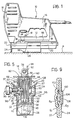
- Figure 1 is a side elevational view of the rivetting machine,
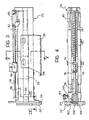
- Figure 2 is an exploded perspective view of the channel and of the parts associated therewith,
- Figure 3 is a side elevational view, to an enlarged scale with respect to Figure 1, showing only the lower unit of the rivetting machine, defining the channel,
- Figure 4 is a view of the unit of Figure 3 from above,
- Figure 5 is a cross-sectional view, to an enlarged scale, taken on line V-V of Figure 4,
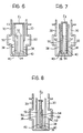
- Figures 6 to 8 are cross-sections of the channel, which illustrate the manner in which various rivetting elements are guided, and
- Figure 9 is a partial section, to an enlarged scale, taken on line IX-IX of Figure 3.
- Referring to Figure 1, a rivetting machine comprises, in known manner, a
body 10 with abase part 12, apart 14 acting as a handgrip and ahead 16. In thehead 16 is housed, in known manner, an electromagnet which can be selectively energised by means of atrigger 18 to cause a blade punch for discharging staples from the machine, to descend. - Under the
base part 12 is fixed a sheet-metal channel 20 which accommodates a series of rivet elements. As will be seen below, these elements are urged towards the end of thechannel 20 underlying thehead 16 where the blade punch discharges them one by one through a slit defined by a pair ofmating plates - A
slidable foot 26 is connected to thechannel 20 for supporting the rivetting machine on the working surface P. - Referring to Figures 2 to 5, the
channel 20 includes an outer sheet-metal element 28 of substantially U-shaped profile, withside walls 30 and abase wall 32. Within theouter element 28 there is located a further U-shaped, sheet-metal element 34 which has abase wall 36 applied to thewall 32, and twoside walls 38. - Within the
inner U-shaped element 34 are located two parallel sheet-metal strips 40 provided withtabs 42 along their edges facing the bottom of the channel. Thetabs 42 are inserted inrespective slits 44 in theinternal element 34 and slits 46 in theouter element 28 and are upset to secure all theelements - As illustrated in Figures 5 to 8, the
walls 38 andstrips 40 define respective pairs of longitudinal dividing walls which extend up from the base wall of the channel and which define a pair of outermost interstices 50 (between thewalls 30 and the walls 38), a pair of innermost interstices 52 (between thedividing walls 38 and 40), as well as a central space 54 (between the dividing walls 40). The dividingwalls 38 are higher than the dividingwalls 40. - A
pusher 56 is slidable in thechannel 20 and comprises an outer sheet-metal element 58 in the form of an upturned U with a pair ofsides 60 and anupper yoke 62. - An internal sheet-
metal element 64 is located within theouter element 58 and has an upturned U profile with a pair ofside walls 66 and anupper yoke 67. - Within the
internal U-shaped element 64 is located aplate element 68 which hastabs 70 on its upper edge. The tabs are inserted inrespective slits 72 in theinternal U-shaped element 64 and slits 74 in theouter U-shaped element 58, and are upset to secure the threeelements - As may be seen in Figure 5, the
walls channel 20. As will be understood below, these blades serve to engage the rear end of the respective series of rivet elements and push them towards the discharge end of thechannel 20. - Projecting from the
upper yoke 62 of theouter U-shaped element 58 is a pair oflugs 76 through which alongitudinal guide rod 78 can slide. Ahook member 80 of shaped sheet-metal is fixed to the rear end of therod 78 and can be hooked, in known manner, to the entry end of thechannel 20. Ahelical spring 82 is interposed between thepusher 56 and thehook member 80 for the purpose of resiliently urging a series of staples along thechannel 20 by means of the blades of thepusher 56. - An
appendage 84 in the form of a plaque bearing areference mark 86 is mounted on therod 78 between thelugs 76. Theplaque 84 projects through a slot between thechannel 20 and thebase part 12 of thebody 10 and is movable along a scale 88 (Figure 1) to indicate the position of thepusher 58 in thechannel 20 and hence the quantity of rivet elements contained in the channel itself. - The
side walls 30 of the channel have respectivelongitudinal ribs 90 which define correspondinginternal grooves 92. In thesegrooves 92 are guided correspondinglongitudinal ribs 94 of thepusher 56. This coupling has the object of preventing thepusher 56 from inclining with respect to its direction of sliding, since inclination of the pusher could cause the rivet elements to jam, especially the last element to be discharged. - The
foot 26 is constituted by a substantially U-shaped sheet-metal element. In the upper part of its side wall, it has respective steppedwings 96 which embrace theribs 90.Tabs 97 are formed in thewings 96 by semi-punching and engage the upper parts of theribs 90. In this manner, thefoot 26 is mounted for sliding movement along thechannel 20. - The
foot 26 has afront projecting part 98 which, when the foot is in its fully advanced position, is disposed beneath theplates foot 26 can be fixed in this advanced position by means of a side screw 99 (Figure 5) which can be screwed into one of the side walls of thechannel 20 through a corresponding hole in thefoot 26, one of the ends of which, moreover, is arranged to be in front of thepusher 56 to prevent its advancement. - Referring to Figure 6, a first type of rivetting element is shown as E, and is constituted by a relatively wide, short staple. The transverse or yoke part of the element E, rests on the upper edges of the outermost pair of dividing
walls 38 and the legs of the element E, are located in theoutermost interstices 50 and slidingly embrace thedividing walls 38. - The pusher 20 (Figure 5) pushes the series of elements E1 by means of its outermost blades or
sides 60. - In Figure 7 is shown a second type of rivet element E2 which is relatively narrow and long. The points or lower ends of the legs of the element E2 rest on the base wall of the channel or rather on the
base wall 36 of the innermost U-shaped element, and these legs are guided in theinterstices 52 between the two pairs of dividingwalls - The pusher 56 (Figure 5) pushes the series of elements E2 by means of its pair of
blades 66. - In Figure 8 is shown a further rivet element E3 constituted by a rivet. The point of the rivet rests on the
base wall 36 and is guided within thecentral interstice 54 by means of the two dividingwalls 40. - The pusher (Figure 5) pushes the series of rivets by means of its
middle blade 68. - Referring now to Figure 9, as well as to Figures 2 and 4, the discharge slit at the end of the
channel 20 through which the blade punch of the rivetting machine expels the rivet elements one by one, is indicated by 100. Theslit 100 is defined between two mating plates, afront plate 22 and arear plate 24. Thefront plate 22 is formed with awide groove 102 of a width such as to guide the rivet element E1 as well as the blade punch (not shown). Thefront plate 22 is also formed with a narrowcentral guide groove 104 for the rivet element or rivet E3. - The
rear plate 24 is formed with agroove 106 of intermediate width which serves as a guide for the rivet element E2.
Claims (6)
Priority Applications (1)
| Application Number | Priority Date | Filing Date | Title |
|---|---|---|---|
| AT82830191T ATE26940T1 (en) | 1981-07-02 | 1982-06-28 | PORTABLE RIVETING MACHINE. |
Applications Claiming Priority (2)
| Application Number | Priority Date | Filing Date | Title |
|---|---|---|---|
| ITTO1981U53404U IT8153404U1 (en) | 1981-07-02 | 1981-07-02 | PORTABLE NAILER |
| IT5340481U | 1981-07-02 |
Publications (3)
| Publication Number | Publication Date |
|---|---|
| EP0069710A2 EP0069710A2 (en) | 1983-01-12 |
| EP0069710A3 EP0069710A3 (en) | 1983-09-07 |
| EP0069710B1 true EP0069710B1 (en) | 1987-05-06 |
Family
ID=11282445
Family Applications (1)
| Application Number | Title | Priority Date | Filing Date |
|---|---|---|---|
| EP82830191A Expired EP0069710B1 (en) | 1981-07-02 | 1982-06-28 | Portable rivetting machine |
Country Status (4)
| Country | Link |
|---|---|
| EP (1) | EP0069710B1 (en) |
| AT (1) | ATE26940T1 (en) |
| DE (1) | DE3207962A1 (en) |
| IT (1) | IT8153404U1 (en) |
Cited By (1)
| Publication number | Priority date | Publication date | Assignee | Title |
|---|---|---|---|---|
| US12162125B2 (en) | 2020-10-30 | 2024-12-10 | Milwaukee Electric Tool Corporation | Powered fastener driver |
Families Citing this family (16)
| Publication number | Priority date | Publication date | Assignee | Title |
|---|---|---|---|---|
| DE3315411C2 (en) * | 1983-04-28 | 1986-04-03 | Joh. Friedrich Behrens AG, 2070 Ahrensburg | Magazine for power driven driving tool |
| GB2150486A (en) * | 1983-12-02 | 1985-07-03 | Umberto Monacelli | Guide bench for guiding fasteners and fastener driving apparatus having such a guide bench |
| US4732309A (en) * | 1984-08-10 | 1988-03-22 | Black & Decker, Inc. | Staple magazine |
| US4667865A (en) * | 1984-08-10 | 1987-05-26 | Black & Decker, Inc. | Staple magazine for multiple width staples |
| GB2165793A (en) * | 1984-10-13 | 1986-04-23 | Su Shing Nan | Multi-purpose stapler |
| DE3500279C2 (en) * | 1985-01-05 | 1987-03-26 | Esco Metallwaren, Martin Hühnken, 2072 Bargteheide | Magazine for power-driven tackers |
| GB2204261A (en) * | 1987-04-30 | 1988-11-09 | Lin Chung Cheng | Electric binding/stapling machine |
| DE8710524U1 (en) * | 1987-07-31 | 1987-10-01 | Erwin Müller GmbH & Co, 4450 Lingen | Magazine of a driving tool for holding fasteners |
| GB9025131D0 (en) * | 1990-11-19 | 1991-01-02 | Ofrex Group Holdings Plc | Improvements in or relating to a stapling machine |
| DE4109362A1 (en) * | 1991-03-22 | 1992-09-24 | Bosch Gmbh Robert | DRIVING DEVICE FOR STAPLES |
| DE4222003A1 (en) * | 1992-07-04 | 1994-01-05 | Leitz Louis Kg | Stapler |
| FR2728824B1 (en) * | 1994-12-30 | 1997-06-20 | Bossard Jacques Jean Claude | STAPLER FOR AT LEAST TWO KINDS OF STAPLES |
| US5695108A (en) * | 1996-03-05 | 1997-12-09 | De Poan Pneumatic Corporation | Magazine system of a stapler |
| US6715657B2 (en) * | 2002-04-29 | 2004-04-06 | Mu-Yu Chen | Magazine for use in nail stapler |
| IT1392448B1 (en) * | 2009-01-19 | 2012-03-09 | Nikema Srl | LOADER OF FIXING ELEMENTS FOR PNEUMATIC GUNS |
| CN102133747B (en) * | 2010-01-27 | 2012-07-25 | 丰民金属工业股份有限公司 | Nailer for various sizes of staples |
Family Cites Families (4)
| Publication number | Priority date | Publication date | Assignee | Title |
|---|---|---|---|---|
| US3156920A (en) * | 1962-03-23 | 1964-11-17 | Fastener Corp | Magazine construction |
| DE1908012A1 (en) * | 1969-02-18 | 1970-08-27 | Behrens Friedrich Joh | Device for driving various types of fasteners |
| US3958738A (en) * | 1974-10-18 | 1976-05-25 | Usm Corporation | Staple gun for accommodating a range of staple sizes |
| FR2490534A1 (en) * | 1980-08-27 | 1982-03-26 | Guyon Eric | Loading magazine and blade hammer for stapler - has ejection slot and guide channel to accommodate largest size staples and staple rails to accommodate smallest |
-
1981
- 1981-07-02 IT ITTO1981U53404U patent/IT8153404U1/en unknown
-
1982
- 1982-03-05 DE DE19823207962 patent/DE3207962A1/en active Granted
- 1982-06-28 EP EP82830191A patent/EP0069710B1/en not_active Expired
- 1982-06-28 AT AT82830191T patent/ATE26940T1/en not_active IP Right Cessation
Cited By (1)
| Publication number | Priority date | Publication date | Assignee | Title |
|---|---|---|---|---|
| US12162125B2 (en) | 2020-10-30 | 2024-12-10 | Milwaukee Electric Tool Corporation | Powered fastener driver |
Also Published As
| Publication number | Publication date |
|---|---|
| DE3207962C2 (en) | 1991-09-05 |
| IT8153404V0 (en) | 1981-07-02 |
| EP0069710A2 (en) | 1983-01-12 |
| ATE26940T1 (en) | 1987-05-15 |
| EP0069710A3 (en) | 1983-09-07 |
| IT8153404U1 (en) | 1983-01-02 |
| DE3207962A1 (en) | 1983-01-20 |
Similar Documents
| Publication | Publication Date | Title |
|---|---|---|
| EP0069710A2 (en) | Portable rivetting machine | |
| US3958738A (en) | Staple gun for accommodating a range of staple sizes | |
| EP1230070B1 (en) | Nail magazine for a power nailer | |
| US3266697A (en) | Fastener driving apparatus | |
| EP0539138B1 (en) | Fastener-driving tool with improved feeding mechanims | |
| US6415514B1 (en) | Artistic knife with replaceable blade magazine | |
| US5931364A (en) | Fastening tool for securing an object to a substrate | |
| US6745474B1 (en) | Blade pushing device of cutting knives | |
| US4450998A (en) | Staple-driving tools | |
| EP0640445A1 (en) | Spring actuated fastener driving tool | |
| US6493893B1 (en) | Multi-purpose hand-held device | |
| US4667865A (en) | Staple magazine for multiple width staples | |
| US2716749A (en) | Stapling machine for simultaneously inserting at least two staples | |
| US20060213950A1 (en) | Spring energized desktop stapler | |
| US5009356A (en) | Removable magazine for staple guns | |
| US4749115A (en) | Magazine for a power-driven drive-in apparatus for the accommodation of pins or nails or the like | |
| CA1115901A (en) | Office stapler device | |
| US3034128A (en) | Stapling device | |
| US2340717A (en) | Stapling machine | |
| US3892036A (en) | Safety razor | |
| US3437250A (en) | Fastener driving tool | |
| EP0238269A1 (en) | Driver for framer's and glazier's points | |
| US3940044A (en) | Fastener driver with safety device | |
| WO1993023209A1 (en) | An appliance for driving sharp pointed fastener elements into objects | |
| US2445178A (en) | Fastener-applying implement |
Legal Events
| Date | Code | Title | Description |
|---|---|---|---|
| PUAI | Public reference made under article 153(3) epc to a published international application that has entered the european phase |
Free format text: ORIGINAL CODE: 0009012 |
|
| AK | Designated contracting states |
Designated state(s): AT BE CH FR GB IT LI LU NL SE |
|
| PUAL | Search report despatched |
Free format text: ORIGINAL CODE: 0009013 |
|
| RAP1 | Party data changed (applicant data changed or rights of an application transferred) |
Owner name: T.M.M.P. - S.R.L. |
|
| AK | Designated contracting states |
Designated state(s): AT BE CH FR GB IT LI LU NL SE |
|
| 17P | Request for examination filed |
Effective date: 19840125 |
|
| RAP1 | Party data changed (applicant data changed or rights of an application transferred) |
Owner name: LANDIS & GYR - S.P.A. |
|
| GRAA | (expected) grant |
Free format text: ORIGINAL CODE: 0009210 |
|
| AK | Designated contracting states |
Kind code of ref document: B1 Designated state(s): AT BE CH FR GB IT LI LU NL SE |
|
| REF | Corresponds to: |
Ref document number: 26940 Country of ref document: AT Date of ref document: 19870515 Kind code of ref document: T |
|
| ITF | It: translation for a ep patent filed | ||
| ET | Fr: translation filed | ||
| PLBE | No opposition filed within time limit |
Free format text: ORIGINAL CODE: 0009261 |
|
| STAA | Information on the status of an ep patent application or granted ep patent |
Free format text: STATUS: NO OPPOSITION FILED WITHIN TIME LIMIT |
|
| 26N | No opposition filed | ||
| ITTA | It: last paid annual fee | ||
| EPTA | Lu: last paid annual fee | ||
| EAL | Se: european patent in force in sweden |
Ref document number: 82830191.1 |
|
| PG25 | Lapsed in a contracting state [announced via postgrant information from national office to epo] |
Ref country code: LU Free format text: LAPSE BECAUSE OF NON-PAYMENT OF DUE FEES Effective date: 19970628 |
|
| PGFP | Annual fee paid to national office [announced via postgrant information from national office to epo] |
Ref country code: SE Payment date: 19980507 Year of fee payment: 17 |
|
| PGFP | Annual fee paid to national office [announced via postgrant information from national office to epo] |
Ref country code: GB Payment date: 19980522 Year of fee payment: 17 |
|
| PGFP | Annual fee paid to national office [announced via postgrant information from national office to epo] |
Ref country code: NL Payment date: 19980527 Year of fee payment: 17 |
|
| PGFP | Annual fee paid to national office [announced via postgrant information from national office to epo] |
Ref country code: BE Payment date: 19980604 Year of fee payment: 17 |
|
| PGFP | Annual fee paid to national office [announced via postgrant information from national office to epo] |
Ref country code: LU Payment date: 19981021 Year of fee payment: 17 |
|
| PG25 | Lapsed in a contracting state [announced via postgrant information from national office to epo] |
Ref country code: GB Free format text: LAPSE BECAUSE OF NON-PAYMENT OF DUE FEES Effective date: 19990628 |
|
| PG25 | Lapsed in a contracting state [announced via postgrant information from national office to epo] |
Ref country code: SE Free format text: THE PATENT HAS BEEN ANNULLED BY A DECISION OF A NATIONAL AUTHORITY Effective date: 19990629 |
|
| PG25 | Lapsed in a contracting state [announced via postgrant information from national office to epo] |
Ref country code: BE Free format text: LAPSE BECAUSE OF NON-PAYMENT OF DUE FEES Effective date: 19990630 |
|
| PGFP | Annual fee paid to national office [announced via postgrant information from national office to epo] |
Ref country code: FR Payment date: 19990930 Year of fee payment: 18 |
|
| PGFP | Annual fee paid to national office [announced via postgrant information from national office to epo] |
Ref country code: AT Payment date: 19991013 Year of fee payment: 18 |
|
| PGFP | Annual fee paid to national office [announced via postgrant information from national office to epo] |
Ref country code: CH Payment date: 19991018 Year of fee payment: 18 |
|
| BERE | Be: lapsed |
Owner name: LANDIS & GYR - S.P.A. Effective date: 19990630 |
|
| PG25 | Lapsed in a contracting state [announced via postgrant information from national office to epo] |
Ref country code: NL Free format text: LAPSE BECAUSE OF NON-PAYMENT OF DUE FEES Effective date: 20000101 |
|
| GBPC | Gb: european patent ceased through non-payment of renewal fee |
Effective date: 19990628 |
|
| EUG | Se: european patent has lapsed |
Ref document number: 82830191.1 |
|
| NLV4 | Nl: lapsed or anulled due to non-payment of the annual fee |
Effective date: 20000101 |
|
| PG25 | Lapsed in a contracting state [announced via postgrant information from national office to epo] |
Ref country code: AT Free format text: LAPSE BECAUSE OF NON-PAYMENT OF DUE FEES Effective date: 20000628 |
|
| PG25 | Lapsed in a contracting state [announced via postgrant information from national office to epo] |
Ref country code: LI Free format text: LAPSE BECAUSE OF NON-PAYMENT OF DUE FEES Effective date: 20000630 Ref country code: CH Free format text: LAPSE BECAUSE OF NON-PAYMENT OF DUE FEES Effective date: 20000630 |
|
| REG | Reference to a national code |
Ref country code: CH Ref legal event code: PL |
|
| PG25 | Lapsed in a contracting state [announced via postgrant information from national office to epo] |
Ref country code: FR Free format text: LAPSE BECAUSE OF NON-PAYMENT OF DUE FEES Effective date: 20010228 |
|
| REG | Reference to a national code |
Ref country code: FR Ref legal event code: ST |