EP0069503B1 - A security device - Google Patents
A security device Download PDFInfo
- Publication number
- EP0069503B1 EP0069503B1 EP82303247A EP82303247A EP0069503B1 EP 0069503 B1 EP0069503 B1 EP 0069503B1 EP 82303247 A EP82303247 A EP 82303247A EP 82303247 A EP82303247 A EP 82303247A EP 0069503 B1 EP0069503 B1 EP 0069503B1
- Authority
- EP
- European Patent Office
- Prior art keywords
- stack
- arm
- security device
- support means
- carpets
- Prior art date
- Legal status (The legal status is an assumption and is not a legal conclusion. Google has not performed a legal analysis and makes no representation as to the accuracy of the status listed.)
- Expired
Links
- 230000000452 restraining effect Effects 0.000 claims description 2
- 230000000694 effects Effects 0.000 description 2
- 238000000034 method Methods 0.000 description 2
Images

Classifications
-
- B—PERFORMING OPERATIONS; TRANSPORTING
- B65—CONVEYING; PACKING; STORING; HANDLING THIN OR FILAMENTARY MATERIAL
- B65G—TRANSPORT OR STORAGE DEVICES, e.g. CONVEYORS FOR LOADING OR TIPPING, SHOP CONVEYOR SYSTEMS OR PNEUMATIC TUBE CONVEYORS
- B65G1/00—Storing articles, individually or in orderly arrangement, in warehouses or magazines
- B65G1/02—Storage devices
- B65G1/14—Stack holders or separators
-
- B—PERFORMING OPERATIONS; TRANSPORTING
- B65—CONVEYING; PACKING; STORING; HANDLING THIN OR FILAMENTARY MATERIAL
- B65G—TRANSPORT OR STORAGE DEVICES, e.g. CONVEYORS FOR LOADING OR TIPPING, SHOP CONVEYOR SYSTEMS OR PNEUMATIC TUBE CONVEYORS
- B65G57/00—Stacking of articles
Definitions
- This invention relates to a security device for retaining a plurality of floor carpets in a stack.
- a disadvantage of such a system is that there is no provision for discouraging pilfering of carpets.
- a security device for retaininga plurality of floor carpet articles in a stack comprising an arm having a spike depending therefrom and support means for the arm whereby the arm is adapted to be located above the stack and is movable relative to the stack in a direction longitudinally of the spike towards an upper surface of an upper article of the stack so that the spike pierces the upper article and retains the upper article on the stack.
- the arm may be adjustable relative to the support means in a direction longitudinally of the spike.
- the support means may comprise a plurality of components adapted to co-operate one with another to adjust selectively the height of the arm relative to the stack.
- the support means may include securing means for restraining relative movement of said components, the securing means being operable to permit said relative movement.
- the arm may comprise a plurality of components pivotally connected one to another.
- the arm may be provided with a plurality of said spikes.
- the support means may comprise a base for extending under the stack.
- the support means may also comprise cooperating telescopic members upstanding from the base.
- FIG. 1 and 2 of the drawings there is shown a device 10 for retaining uppermost carpets 11, 12, 13, 14 and 15 of a stack 16 of such carpets.
- the device 10 comprises a rectangular base plate 17 having a tubular member 18 upstanding therefrom at a location adjacent an edge of the base plate 17.
- the tubular member 18 is of rectangular transverse cross-section and is at an upper portion thereof provided with a stud (not shown) extending transversely inwardly of the tubular member 18 and being movable relative to the tubular member 18 in a direction transversely thereof.
- the stud is included in a locking mechanism 19 having a slot 20 for receiving a key (not shown). The arrangement is such that, when the key is inserted in the slot 20 and is turned, the stud is withdrawn from the bore of the tubular member 18 against a resilient bias. When the key is returned to the original inserted position, the stud is returned inwardly of the bore of the tubular member 18 due to the resilient bias.
- the tubular member 18 has located therein an elongate member 21 slidable longitudinally in the tubular member 18 when the stud is withdrawn from the bore of the tubular member 18.
- the elongate member 21 is provided with a plurality of apertures 22 spaced longitudinally thereof each aperture 22 being adapted to receive an end portion of the stud when the stud extends inwardly of the bore of the tubular member 18 thereby selectively locating the elongate member 21 longitudinally of the tubular member 18.
- the elongate member 21 is provided, at an end portion thereof remote from the tubular member 18, with an integral sleeve portion 23 having a rectangular bore (not shown).
- the central longitudinal axis of the bore of the sleeve portion 23 is inclined downwardly towards the base plate 17 and the bore has extending therethrough an elongate carrier 24 of inverted U-shape transverse cross section, the dimensions of the bore of the sleeve portion 23 and the carrier 24, in transverse cross-section, being such that the carrier is movable longitudinally of the bore of the sleeve portion 23.
- An end portion of the carrier 24 is provided with a stop 25 limiting movement of the carrier 24 longitudinally of the bore of the sleeve portion 23.
- the carrier 24 has received therein a portion of an elongate arm 26 of substantially rectangular transverse cross-section, the arrangement being such that the arm 26 is pivotally connected midway intermediate opposite end portions thereof by a pin 27.
- the arm 26 is provided with a plurality of depending needles 28 spaced longitudinally of the arm.
- a carpet is located on the base 17 and further carpets are stacked one on top of another on the first carpet to provide the stack 16 of carpets.
- the key is inserted in the slot 20 of the locking mechanism 19 and turned with a result that the stud is withdrawn from the bore of the tubular member 18.
- the elongate member 21 is inserted longitudinally into the tubular member 18 and lowered therein so that the needles 28 pierce the uppermost carpets 11, 12, 13, 14 and 15 of the stack of carpets 16.
- the key then is returned to the originally inserted position and withdrawn from the slot 20 of the locking mechanism 19.
- the stud is released and is urged by the resilient bias towards the elongate member 21.
- the arm 26 is moved downwardly so that the elongate member 21 moves relative to the tubular member 18 until the stud snaps into engagement with an aperture 22 in the elongate member 21.
- the arm 26 thus is restrained from being lifted upwardly from the stack of carpets 16 and each of the carpets 11, 12, 13, 14 and 15 is restrained from being moved relative one to another due to the needles 28 extending therethrough.
- the weight of the uppermost carpets 11, 12, 13, 14 and 15 on the remaining carpets in the stack 16 is such that the carpets 11 to 15 inclusive generally cannot be lifted to remove carpets of the stack 16 located below the lowermost carpet 15.
- the needles 28 are standard and cause no damage to carpets. Furthermore, it will be appreciated that the needles 28 may be removably attached to the arm 26. It will also be appreciated that, in the case of aged carpets which, when arranged in stack result in at least upper carpets of the stack extending in curved configuration, the apparatus in accordance with the present invention compensates for such curvature due to the pivotable connection of the arm 26 and the carrier 24.
- a device 29 similar to the device 10 except that, in the device 29, an arm 30 is provided with an integral disc 31 at an outer end portion thereof, the plane of the disc extending substantially parallel to the plane of carpets in a stack 16, and an opposite end portion thereof is integral with a depending elongate member 32 corresponding to the elongate member 21 of the device 10.
- the disc is provided with depending needles 33.
- the device 29 corresponds with the device 10.
Landscapes
- Engineering & Computer Science (AREA)
- Mechanical Engineering (AREA)
- Burglar Alarm Systems (AREA)
- Sheets, Magazines, And Separation Thereof (AREA)
Abstract
Description
- This invention relates to a security device for retaining a plurality of floor carpets in a stack.
- It is known in the retail trade to stack carpets one on top of another for convenience of storage and for convenience of display. Generally, the procedure is that a prospective purchaser removes a selected carpet from a stack of carpets and the carpet is taken to a station at which sale of the carpet is transacted.
- A disadvantage of such a system is that there is no provision for discouraging pilfering of carpets.
- According to the present invention there is provided a security device for retaininga plurality of floor carpet articles in a stack comprising an arm having a spike depending therefrom and support means for the arm whereby the arm is adapted to be located above the stack and is movable relative to the stack in a direction longitudinally of the spike towards an upper surface of an upper article of the stack so that the spike pierces the upper article and retains the upper article on the stack.
- The arm may be adjustable relative to the support means in a direction longitudinally of the spike.
- The support means may comprise a plurality of components adapted to co-operate one with another to adjust selectively the height of the arm relative to the stack.
- The support means may include securing means for restraining relative movement of said components, the securing means being operable to permit said relative movement.
- The arm may comprise a plurality of components pivotally connected one to another.
- The arm may be provided with a plurality of said spikes.
- The support means may comprise a base for extending under the stack.
- The support means may also comprise cooperating telescopic members upstanding from the base.
- Following is a description, by way of example only and with reference to the accompanying drawings, of one method of carrying the invention into effect.
- In the drawings:-
- FIGURE 1 is an elevation of one embodiment of a device in accordance with the present invention shown in juxtaposition with a stack of floor carpet articles,
- FIGURE 2 is a perspective view of the embodiment shown in Figure 1,
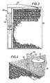
- FIGURE 3 is an elevation of another embodiment of a device in accordance with the present invention shown in juxtaposition with a stack of floor carpet articles, and
- FIGURE 4 is a perspective view of the embodiment shown in Figure 3.
- Referring now to Figures 1 and 2 of the drawings, there is shown a
device 10 for retaininguppermost carpets stack 16 of such carpets. - The
device 10 comprises arectangular base plate 17 having atubular member 18 upstanding therefrom at a location adjacent an edge of thebase plate 17. Thetubular member 18 is of rectangular transverse cross-section and is at an upper portion thereof provided with a stud (not shown) extending transversely inwardly of thetubular member 18 and being movable relative to thetubular member 18 in a direction transversely thereof. The stud is included in alocking mechanism 19 having a slot 20 for receiving a key (not shown). The arrangement is such that, when the key is inserted in the slot 20 and is turned, the stud is withdrawn from the bore of thetubular member 18 against a resilient bias. When the key is returned to the original inserted position, the stud is returned inwardly of the bore of thetubular member 18 due to the resilient bias. - The
tubular member 18 has located therein an elongate member 21 slidable longitudinally in thetubular member 18 when the stud is withdrawn from the bore of thetubular member 18. The elongate member 21 is provided with a plurality of apertures 22 spaced longitudinally thereof each aperture 22 being adapted to receive an end portion of the stud when the stud extends inwardly of the bore of thetubular member 18 thereby selectively locating the elongate member 21 longitudinally of thetubular member 18. The elongate member 21 is provided, at an end portion thereof remote from thetubular member 18, with anintegral sleeve portion 23 having a rectangular bore (not shown). The central longitudinal axis of the bore of thesleeve portion 23 is inclined downwardly towards thebase plate 17 and the bore has extending therethrough anelongate carrier 24 of inverted U-shape transverse cross section, the dimensions of the bore of thesleeve portion 23 and thecarrier 24, in transverse cross-section, being such that the carrier is movable longitudinally of the bore of thesleeve portion 23. An end portion of thecarrier 24 is provided with astop 25 limiting movement of thecarrier 24 longitudinally of the bore of thesleeve portion 23. Thecarrier 24 has received therein a portion of anelongate arm 26 of substantially rectangular transverse cross-section, the arrangement being such that thearm 26 is pivotally connected midway intermediate opposite end portions thereof by apin 27. Thearm 26 is provided with a plurality of dependingneedles 28 spaced longitudinally of the arm. - In use, a carpet is located on the
base 17 and further carpets are stacked one on top of another on the first carpet to provide thestack 16 of carpets. The key is inserted in the slot 20 of thelocking mechanism 19 and turned with a result that the stud is withdrawn from the bore of thetubular member 18. The elongate member 21 is inserted longitudinally into thetubular member 18 and lowered therein so that theneedles 28 pierce theuppermost carpets carpets 16. The key then is returned to the originally inserted position and withdrawn from the slot 20 of thelocking mechanism 19. In consequence, the stud is released and is urged by the resilient bias towards the elongate member 21. Thearm 26 is moved downwardly so that the elongate member 21 moves relative to thetubular member 18 until the stud snaps into engagement with an aperture 22 in the elongate member 21. - The
arm 26 thus is restrained from being lifted upwardly from the stack ofcarpets 16 and each of thecarpets needles 28 extending therethrough. The weight of theuppermost carpets stack 16 is such that the carpets 11 to 15 inclusive generally cannot be lifted to remove carpets of thestack 16 located below thelowermost carpet 15. - In order to remove any one of the carpets comprising the
stack 16, it is necessary to insert the key (which normally would be in the possession of a person of authority) into the slot 20 of thelocking mechanism 19 and to effect turning of the key in order to operate the locking mechanism and lift thecarrier 24 and, in consequence, thearm 26 andneedles 28 from the stack ofcarpets 16. In this manner, pilferage of carpets from the stack is substantially reduced. - It will be appreciated that the
needles 28 are standard and cause no damage to carpets. Furthermore, it will be appreciated that theneedles 28 may be removably attached to thearm 26. It will also be appreciated that, in the case of aged carpets which, when arranged in stack result in at least upper carpets of the stack extending in curved configuration, the apparatus in accordance with the present invention compensates for such curvature due to the pivotable connection of thearm 26 and thecarrier 24. - Referring now to Figures 3 and 4 of the drawings, there is shown a
device 29 similar to thedevice 10 except that, in thedevice 29, anarm 30 is provided with anintegral disc 31 at an outer end portion thereof, the plane of the disc extending substantially parallel to the plane of carpets in astack 16, and an opposite end portion thereof is integral with a dependingelongate member 32 corresponding to the elongate member 21 of thedevice 10. The disc is provided with dependingneedles 33. In all other respects thedevice 29 corresponds with thedevice 10.
Claims (8)
Priority Applications (1)
| Application Number | Priority Date | Filing Date | Title |
|---|---|---|---|
| AT82303247T ATE13169T1 (en) | 1981-06-22 | 1982-06-22 | SECURITY DEVICE. |
Applications Claiming Priority (2)
| Application Number | Priority Date | Filing Date | Title |
|---|---|---|---|
| GB8119176 | 1981-06-22 | ||
| GB8119176 | 1981-06-22 |
Publications (2)
| Publication Number | Publication Date |
|---|---|
| EP0069503A1 EP0069503A1 (en) | 1983-01-12 |
| EP0069503B1 true EP0069503B1 (en) | 1985-05-08 |
Family
ID=10522719
Family Applications (1)
| Application Number | Title | Priority Date | Filing Date |
|---|---|---|---|
| EP82303247A Expired EP0069503B1 (en) | 1981-06-22 | 1982-06-22 | A security device |
Country Status (3)
| Country | Link |
|---|---|
| EP (1) | EP0069503B1 (en) |
| AT (1) | ATE13169T1 (en) |
| DE (1) | DE3263666D1 (en) |
Families Citing this family (3)
| Publication number | Priority date | Publication date | Assignee | Title |
|---|---|---|---|---|
| AU592871B2 (en) * | 1986-05-16 | 1990-01-25 | Gordon Taylor | Improvements in or relating to pallet handling |
| DE4003448A1 (en) * | 1990-02-06 | 1991-08-08 | Ver Glaswerke Gmbh | TRANSPORT PALLET FOR CAR GLASS PANELS |
| AT412779B (en) * | 2004-02-06 | 2005-07-25 | Friederike Moser | Tensioning device for securing stacked loading goods comprises a belt-tensioning roller arranged in the region of the open upper end of a molded tube of a housing lower part and tensioning a belt connecting this part to a sliding part |
Family Cites Families (5)
| Publication number | Priority date | Publication date | Assignee | Title |
|---|---|---|---|---|
| DD67357A (en) * | ||||
| DE1661569U (en) * | 1953-06-26 | 1953-08-20 | Wolfgang Allihn | SECURING DEVICE FOR WOODEN STACKS. |
| DE2335965A1 (en) * | 1973-07-14 | 1975-01-30 | Orschler Produktion Kg | Thief proof lockable tape cassette rack - uses expanding cassette frames held between lockable carrier bars |
| US4069927A (en) * | 1976-04-21 | 1978-01-24 | Taylor Charles F | Anchor member for unitizing a plurality of containers |
| US4247092A (en) * | 1979-06-01 | 1981-01-27 | D. W. Zimmerman Mfg., Inc. | Apparatus for handling a plurality of signature bundles |
-
1982
- 1982-06-22 DE DE8282303247T patent/DE3263666D1/en not_active Expired
- 1982-06-22 AT AT82303247T patent/ATE13169T1/en active
- 1982-06-22 EP EP82303247A patent/EP0069503B1/en not_active Expired
Also Published As
| Publication number | Publication date |
|---|---|
| DE3263666D1 (en) | 1985-06-13 |
| ATE13169T1 (en) | 1985-05-15 |
| EP0069503A1 (en) | 1983-01-12 |
Similar Documents
| Publication | Publication Date | Title |
|---|---|---|
| US4527222A (en) | Precision tote box insert for holding and locating printed circuit boards or the like | |
| US4450961A (en) | Display bracket for socket drive units and package employing same | |
| US4505395A (en) | Magazine display tray | |
| EP1227744B1 (en) | Security device for preventing rapid removal of merchandise | |
| US7395938B2 (en) | Method and apparatus for selective engagement of shelf divider structures within a shelf management system | |
| US4545628A (en) | Tool chest with retractable step | |
| US4358035A (en) | Systems for holding small articles in a load compartment | |
| US4344367A (en) | Modular product display system | |
| US6155438A (en) | System and method for product display, arrangement and rotation | |
| US5025937A (en) | Safety lock for rack systems | |
| US4627542A (en) | Display apparatus having a mechanism for tilting shelves | |
| US6543638B2 (en) | Method and means of dispensing T-shirt type bags | |
| US4871218A (en) | Collapsible storage and display device | |
| US4730735A (en) | Tape storage system | |
| US4693382A (en) | Sorter for automotive glove compartments | |
| EP0573426B1 (en) | Theft-deterrent device | |
| JPS62500449A (en) | Stacking containers for molded parts, especially sheet-metal stamped parts | |
| GB2261214A (en) | Article dispenser | |
| JPS6044611A (en) | Target fastener for pilferage detector | |
| EP0069503A1 (en) | A security device | |
| US4697710A (en) | Carpet display stand | |
| GB1573058A (en) | Racks for supporting and displaying articles | |
| US4494788A (en) | Hand portable bottle rack | |
| US5938145A (en) | Wire carousel | |
| US4341314A (en) | Container stop device for refrigerator trays |
Legal Events
| Date | Code | Title | Description |
|---|---|---|---|
| PUAI | Public reference made under article 153(3) epc to a published international application that has entered the european phase |
Free format text: ORIGINAL CODE: 0009012 |
|
| AK | Designated contracting states |
Designated state(s): AT BE CH DE FR GB IT LI LU NL SE |
|
| RAP1 | Party data changed (applicant data changed or rights of an application transferred) |
Owner name: B.C.M.S. ENGINEERING & EXHIBITIONS LIMITED |
|
| 17P | Request for examination filed |
Effective date: 19830707 |
|
| GRAA | (expected) grant |
Free format text: ORIGINAL CODE: 0009210 |
|
| AK | Designated contracting states |
Designated state(s): AT BE CH DE FR GB IT LI LU NL SE |
|
| PG25 | Lapsed in a contracting state [announced via postgrant information from national office to epo] |
Ref country code: LI Effective date: 19850508 Ref country code: IT Free format text: LAPSE BECAUSE OF FAILURE TO SUBMIT A TRANSLATION OF THE DESCRIPTION OR TO PAY THE FEE WITHIN THE PRESCRIBED TIME-LIMIT;WARNING: LAPSES OF ITALIAN PATENTS WITH EFFECTIVE DATE BEFORE 2007 MAY HAVE OCCURRED AT ANY TIME BEFORE 2007. THE CORRECT EFFECTIVE DATE MAY BE DIFFERENT FROM THE ONE RECORDED. Effective date: 19850508 Ref country code: CH Effective date: 19850508 Ref country code: AT Effective date: 19850508 |
|
| REF | Corresponds to: |
Ref document number: 13169 Country of ref document: AT Date of ref document: 19850515 Kind code of ref document: T |
|
| PG25 | Lapsed in a contracting state [announced via postgrant information from national office to epo] |
Ref country code: SE Effective date: 19850530 |
|
| REF | Corresponds to: |
Ref document number: 3263666 Country of ref document: DE Date of ref document: 19850613 |
|
| PG25 | Lapsed in a contracting state [announced via postgrant information from national office to epo] |
Ref country code: LU Free format text: LAPSE BECAUSE OF NON-PAYMENT OF DUE FEES Effective date: 19850630 Ref country code: BE Effective date: 19850630 |
|
| ET | Fr: translation filed | ||
| REG | Reference to a national code |
Ref country code: CH Ref legal event code: PL |
|
| BERE | Be: lapsed |
Owner name: B.C.M.S. ENGINEERING & EXHIBITIONS LTD Effective date: 19850622 |
|
| PG25 | Lapsed in a contracting state [announced via postgrant information from national office to epo] |
Ref country code: NL Effective date: 19860101 |
|
| PG25 | Lapsed in a contracting state [announced via postgrant information from national office to epo] |
Ref country code: FR Free format text: LAPSE BECAUSE OF NON-PAYMENT OF DUE FEES Effective date: 19860228 |
|
| PG25 | Lapsed in a contracting state [announced via postgrant information from national office to epo] |
Ref country code: DE Effective date: 19860301 |
|
| NLV4 | Nl: lapsed or anulled due to non-payment of the annual fee | ||
| PLBE | No opposition filed within time limit |
Free format text: ORIGINAL CODE: 0009261 |
|
| STAA | Information on the status of an ep patent application or granted ep patent |
Free format text: STATUS: NO OPPOSITION FILED WITHIN TIME LIMIT |
|
| REG | Reference to a national code |
Ref country code: FR Ref legal event code: ST |
|
| 26N | No opposition filed | ||
| PG25 | Lapsed in a contracting state [announced via postgrant information from national office to epo] |
Ref country code: GB Effective date: 19880622 |
|
| GBPC | Gb: european patent ceased through non-payment of renewal fee |