EP0069491B1 - Rückhaltendes Lagerstück für eine Drehbahn - Google Patents
Rückhaltendes Lagerstück für eine Drehbahn Download PDFInfo
- Publication number
- EP0069491B1 EP0069491B1 EP82303172A EP82303172A EP0069491B1 EP 0069491 B1 EP0069491 B1 EP 0069491B1 EP 82303172 A EP82303172 A EP 82303172A EP 82303172 A EP82303172 A EP 82303172A EP 0069491 B1 EP0069491 B1 EP 0069491B1
- Authority
- EP
- European Patent Office
- Prior art keywords
- bearing
- bearing block
- slots
- rotary valve
- bore
- Prior art date
- Legal status (The legal status is an assumption and is not a legal conclusion. Google has not performed a legal analysis and makes no representation as to the accuracy of the status listed.)
- Expired
Links
- 239000002184 metal Substances 0.000 claims description 2
- 230000000295 complement effect Effects 0.000 claims 1
- 239000000463 material Substances 0.000 description 3
- 230000006835 compression Effects 0.000 description 2
- 238000007906 compression Methods 0.000 description 2
- 238000003754 machining Methods 0.000 description 2
- 238000005452 bending Methods 0.000 description 1
- 238000010276 construction Methods 0.000 description 1
- 230000000694 effects Effects 0.000 description 1
- 210000004907 gland Anatomy 0.000 description 1
- 238000012986 modification Methods 0.000 description 1
- 230000004048 modification Effects 0.000 description 1
Images
Classifications
-
- F—MECHANICAL ENGINEERING; LIGHTING; HEATING; WEAPONS; BLASTING
- F16—ENGINEERING ELEMENTS AND UNITS; GENERAL MEASURES FOR PRODUCING AND MAINTAINING EFFECTIVE FUNCTIONING OF MACHINES OR INSTALLATIONS; THERMAL INSULATION IN GENERAL
- F16K—VALVES; TAPS; COCKS; ACTUATING-FLOATS; DEVICES FOR VENTING OR AERATING
- F16K5/00—Plug valves; Taps or cocks comprising only cut-off apparatus having at least one of the sealing faces shaped as a more or less complete surface of a solid of revolution, the opening and closing movement being predominantly rotary
- F16K5/06—Plug valves; Taps or cocks comprising only cut-off apparatus having at least one of the sealing faces shaped as a more or less complete surface of a solid of revolution, the opening and closing movement being predominantly rotary with plugs having spherical surfaces; Packings therefor
- F16K5/0647—Spindles or actuating means
-
- F—MECHANICAL ENGINEERING; LIGHTING; HEATING; WEAPONS; BLASTING
- F16—ENGINEERING ELEMENTS AND UNITS; GENERAL MEASURES FOR PRODUCING AND MAINTAINING EFFECTIVE FUNCTIONING OF MACHINES OR INSTALLATIONS; THERMAL INSULATION IN GENERAL
- F16K—VALVES; TAPS; COCKS; ACTUATING-FLOATS; DEVICES FOR VENTING OR AERATING
- F16K27/00—Construction of housing; Use of materials therefor
- F16K27/06—Construction of housing; Use of materials therefor of taps or cocks
- F16K27/067—Construction of housing; Use of materials therefor of taps or cocks with spherical plugs
Definitions
- This invention relates to bearing retainers for a rotary valve as defined in the first part of claim 1.
- Ball valves of the type described and illustrated in U.S. Patent No. 3,348,804 granted October 24, 1967 to J. E. Piccardo have been very successful commercially.
- Such valves comprise a generally circular body band in which a valve ball with integral trunnions is contained.
- Rotatably mounted on the trunnions are bearing retainers with a central bore carrying a suitable rotary bushing, and the bearing retainers are secured in place by clamping the ends thereof between the end closures of the valve housing.
- this valve construction has been generally satisfactory, the clamping of the bearing retainers occasionally results in a "pinching" of the ball trunnions, causing excessive stem torque and a rapid wear of the trunnion bearings.
- valve body the two end closures and the two bearing retainers.
- these components can be extremely heavy and cumbersome, and difficult to handle for precision machining.
- French Patent 2080394 shows an arrangement in which the bearing retainers are essentially cantilevered and hence subject to no clamping forces, these being taken up entirely by the body band. This arrangement has proved to be less satisfactory, however, than arrangements in which the bearing retainers are clamped at both ends particularly under more exacting operational conditions.
- the problem solved by the present invention is to provide an effective rotary valve in which the bearing retainers are clamped between the end closures, but in which clamping forces are effectively diverted away from the bearings.
- force directing means comprising two pairs of parallel slots in the bearing block which slots are situated intermediate the bore receiving the bearing and each of the opposite bearing legs clamped between the eclosures, whereby said slots being so disposed that projected continuations of ech pair thereof are approximately tangential to said bore on opposite sides thereof.
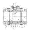
- a ball valve 10 may include a body band 12 of annular configuration, which may be formed from pipe or from plate material which is rolled into a split ring and its ends welded together.
- Bolted at 14 to the annular ends of the body band 12 are end closures 16 which may include integral hubs 18, as well as flanges 20 for connection into a pipeline (not shown).
- Rotatably carried on the trunnions 26 and 28 are bearing blocks or retainers 30 and 32 having central bores 34 to accommodate rotary bushings 35, and the lower bearing retainer 32 may carry thrust bearings 36 to accommodate the weight of the ball 22.
- the bearing retainers 30 and 32 are located with respect to the end closures 16 by means of positioning pins 38 and then clamped between the end closures 16 by tightening the bolts 14.
- Seat rings 40 which are slidable in the body end closures 16 are urged by springs 42 against opposite sides of the ball 22 so that main seals, such as O-rings 44, can effect seals with the surface of the ball 22.
- Outer O-rings 46 are provided to preclude leak paths around the seat rings 40.
- the ball 22 is rotated between the open position shown, with its flow passage 22a aligned with the flow passages 18a of the hubs 18, and a closed position, with the flow passage 22a disposed normal thereto, by means of a stem 48.
- Rotation of the stem 48 is transmitted to the ball 22 by means of a pair of pins 50 which are receivable in holes 52 in the upper trunnion 26.
- the stem is sealed by means of a gland plate 54, and keyed to it is an indicator plate 56 which engages a stop member 58 to indicate position of the valve ball 22.
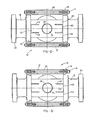
- FIG. 2 there is shown the bearing block 30 of this invention, prior to tightening of the bolts 14, which clamp it between the end closures 16.
- the midportion 60 of each end of the bearing block 30, constituting approximately the area within longitudinal projections of the bore 34 is recessed, so that the lateral portions 62 extend somewhat beyond them to form clamping legs, which bear most of the clamping force from the end closures 60.
- the clamping legs are isolated from the central portions by means of slots 64 and 66.
- the amount of clearance in the centre portion 60 is such that when the bolts are fully tightened, the bearing blocks 30 will be clamped across the widths of the end surfaces 60 and 62.
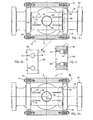
- the bearing block 68 is provided with slots 70 and 72 adjacent each end 74.
- the slots do not extend all the way to the end 74 but terminate in holes 76 and 78 drilled in the bearing block 68.
- the drilled holes 76 and 78 provide simple and accurate means of controlling the location of slots and also function as crack arrestors.
- the means of concentrating the clamping forces laterally outward of the slots 70 and 72 comprise thin metal shims 80 which are folded over at the ends 82 ( Figure 5) to provide a double thickness.
Landscapes
- Engineering & Computer Science (AREA)
- General Engineering & Computer Science (AREA)
- Mechanical Engineering (AREA)
- Taps Or Cocks (AREA)
- Valve Housings (AREA)
- Rolling Contact Bearings (AREA)
Claims (7)
- i 1. Absperrhahn (10) miteinem Gehäuse (12, 18),einem drehbaren Hahnküken (22) in dem Gehäuse,einem Lagerblock (30, 32) mit einer Durchgangsbohrung (34), welcher in dem Gehäuse gelagert ist,einem Bedienungszapfen (26, 28) an dem Hahnküken (22), welcher drehbar in dem Lagerblock (30, 32) gelagert ist,Einrichtungen (14,18, 38) an dem Gehäuse (12, 18), die den Lagerblock (30, 32) zum Festlegen in seiner Lage einspannen,einem Paar von einander gegenüberliegenden seitlich angeordneten Lagerschenkeln (62) an dem Lagerblock (30, 32), welche zwischen komplementären Flächen an dem Gehäuse (12, 18) eingespannt sind, so daß größere Klemmkräfte auf die äußeren Bereiche des Lagerblocks aufgebracht werden,
dadurch gekennzeichnet, daß eine Einrichtung zur Kraftverteilung vorgesehen ist, welche zwei Paare von parallelen Schlitzen (64, 66) in dem Lagerblock (30, 32) aufweist, wobei die Schlitze zwischen der das Lager aufnehmenden Durchgangsbohrung (34) und jedem der einander gegenüberliegenden Lagerschenkel (62) angeordnet sind, die zwischen den endseitigen Abschlußstücken eingeklemmt sind, wobei die Schlitze (64, 66) so angeordnet sind, daß gedachte Verlängerungen eines jeden Paares im wesentlichen tangential zu der Durchgangsbohrung (34) an daran gegenüberliegenden Seiten verlaufen. - 2. Absperrhahn nach Anspruch 1, dadurch gekennzeichnet, daß jedes der Paare der Schlitze (64, 66) sich durchgehend bis zu einer der gegenüberliegenden Flächen (60, 62) erstreckt.
- 3. Absperrhahn nach Anspruch 1 oder 2, dadurch gekennzeichnet, daß eine Bohrung (78) durch den Lagerblock an dem von der Lagerbohrung entfernten Ende eines jeden Schlitzes gebohrt ist.
- 4. Absperrhahn nach einem der Ansprüche 1 bis 3, dadurch gekennzeichnet, daß Bohrungen (76, 78) an beiden Enden der Schlitze durch den Lagerblock gebohrt sind.
- 5. Absperrhahn nach einem der Ansprüche 1 bis 4, dadurch gekennzeichnet, daß die Abmessung des Lagerblocks im unverspannten Zustand von der Mittellinie der Bohrung zu den Außenbereichen der gegenüberliegenden Flächen größer ist als die von der Mittellinie zu den Zwischenbereichen.
- 6. Absperrhahn nach Anspruch 5, dadurch gekennzeichnet, daß die Zwischenbereiche von den Außenbereichen zurückversetzt angeordnet sind.
- 7. Absperrhahn nach Anspruch 6, dadurch gekennzeichnet, daß er eine dünne Metallzwischenscheibe (80) auf jeder der gegenüberliegenden Flächen aufweist, welche an jedem Ende umgeschlagen ist, um die größere Abmessung zu bilden.
Applications Claiming Priority (2)
| Application Number | Priority Date | Filing Date | Title |
|---|---|---|---|
| US06/275,496 US4337919A (en) | 1981-06-22 | 1981-06-22 | Bearing retainers for a rotary valve |
| US275496 | 1981-06-22 |
Publications (2)
| Publication Number | Publication Date |
|---|---|
| EP0069491A1 EP0069491A1 (de) | 1983-01-12 |
| EP0069491B1 true EP0069491B1 (de) | 1985-08-14 |
Family
ID=23052553
Family Applications (1)
| Application Number | Title | Priority Date | Filing Date |
|---|---|---|---|
| EP82303172A Expired EP0069491B1 (de) | 1981-06-22 | 1982-06-17 | Rückhaltendes Lagerstück für eine Drehbahn |
Country Status (5)
| Country | Link |
|---|---|
| US (1) | US4337919A (de) |
| EP (1) | EP0069491B1 (de) |
| JP (1) | JPS5952312B2 (de) |
| CA (1) | CA1177461A (de) |
| DE (1) | DE3265416D1 (de) |
Families Citing this family (15)
| Publication number | Priority date | Publication date | Assignee | Title |
|---|---|---|---|---|
| DE3806871A1 (de) * | 1988-03-03 | 1989-09-14 | Berchem & Schaberg Gmbh | Stellkugelhahn mit gehaeuse, stroemungskanal, hahnkugel und stellspindel |
| GB9100107D0 (en) * | 1991-01-04 | 1991-02-20 | Btr Plc | Valve disc and drive shaft assembly |
| DE4402162A1 (de) * | 1994-01-26 | 1995-07-27 | Klein Schanzlin & Becker Ag | Kugelhahn |
| US5464036A (en) * | 1994-02-09 | 1995-11-07 | Valgro, Ltd. | Orifice fitting with venting passage and injection seal |
| US5755427A (en) * | 1996-02-23 | 1998-05-26 | Naf Ab | Self adjusting ball valve assembly |
| EP0846237B1 (de) * | 1995-09-07 | 2003-07-09 | Naf Aktiebolag | Kugelhahn mit automatischer justierung |
| US5868378A (en) * | 1997-01-28 | 1999-02-09 | Fisher Controls International, Inc. | Throttling control in a fluid control valve |
| US7347408B2 (en) * | 2006-03-07 | 2008-03-25 | Griswold Controls Inc | High differential pressure, low torque precision temperature control valve |
| US8595609B2 (en) * | 2008-05-16 | 2013-11-26 | Parata Systems, Llc | Methods, systems and computer program products for creating and modifying labels used by pharmaceutical dispensing systems |
| US8511640B2 (en) * | 2009-12-22 | 2013-08-20 | Hydac Accessories Gmbh | Ball valve with detachable slide bearing bushes |
| US9547626B2 (en) | 2011-01-29 | 2017-01-17 | Sdl Plc | Systems, methods, and media for managing ambient adaptability of web applications and web services |
| US11308528B2 (en) | 2012-09-14 | 2022-04-19 | Sdl Netherlands B.V. | Blueprinting of multimedia assets |
| CN108413066B (zh) * | 2018-06-04 | 2024-03-22 | 无锡市亚迪流体控制技术有限公司 | 一种固定的球阀的调心结构 |
| US11125350B2 (en) * | 2019-03-12 | 2021-09-21 | Dresser, Llc | Valve control assembly |
| US11686404B2 (en) * | 2020-12-11 | 2023-06-27 | Dresser, Llc | Reducing noise in ball valves |
Family Cites Families (10)
| Publication number | Priority date | Publication date | Assignee | Title |
|---|---|---|---|---|
| DE1072037B (de) * | 1959-12-24 | |||
| US3038693A (en) * | 1960-08-04 | 1962-06-12 | Pacific Valves Inc | Seat adjustment for ball valves with rotatable ring |
| US3277919A (en) * | 1962-10-26 | 1966-10-11 | Grove Valve & Regulator Co | Rotatable valve structure |
| US3348804A (en) * | 1964-06-10 | 1967-10-24 | Grove Valve & Regulator Co | Valve construction |
| US3576309A (en) * | 1969-02-19 | 1971-04-27 | Fmc Corp | Top entry ball valve |
| US3624803A (en) * | 1970-01-19 | 1971-11-30 | Grove Valve & Regulator Co | Bolted valve body construction |
| US3599933A (en) * | 1970-02-05 | 1971-08-17 | Grove Valve & Regulator Co | Rotary valve bearing assembly |
| US3624804A (en) * | 1970-05-18 | 1971-11-30 | Grove Valve & Regulator Co | Fabricated valve body construction |
| US3617025A (en) * | 1970-07-06 | 1971-11-02 | Grove Valve & Regulator Co | Ball valve with retractable seat rings |
| US3737145A (en) * | 1971-08-02 | 1973-06-05 | Walworth Co | Fabricated valve ball |
-
1981
- 1981-06-22 US US06/275,496 patent/US4337919A/en not_active Expired - Fee Related
-
1982
- 1982-06-17 EP EP82303172A patent/EP0069491B1/de not_active Expired
- 1982-06-17 DE DE8282303172T patent/DE3265416D1/de not_active Expired
- 1982-06-21 JP JP57106641A patent/JPS5952312B2/ja not_active Expired
- 1982-06-21 CA CA000405613A patent/CA1177461A/en not_active Expired
Also Published As
| Publication number | Publication date |
|---|---|
| EP0069491A1 (de) | 1983-01-12 |
| US4337919A (en) | 1982-07-06 |
| CA1177461A (en) | 1984-11-06 |
| JPS5842874A (ja) | 1983-03-12 |
| JPS5952312B2 (ja) | 1984-12-19 |
| DE3265416D1 (en) | 1985-09-19 |
Similar Documents
| Publication | Publication Date | Title |
|---|---|---|
| EP0069491B1 (de) | Rückhaltendes Lagerstück für eine Drehbahn | |
| US4113228A (en) | Rotary plug valve | |
| US2882010A (en) | Flow control valve | |
| US4718457A (en) | Diverter valve | |
| US3612483A (en) | Valves with deformable sealing | |
| US4003394A (en) | Disc valve with improved seal ring | |
| US3430919A (en) | Hydraulically balanced plug valve | |
| US4471943A (en) | Valve assembly and seat | |
| US3561471A (en) | Safety valve | |
| US4386756A (en) | Self centering floating metal seal for a ball valve | |
| FI61081B (fi) | Anordning vid ventiler | |
| US4085770A (en) | Seat and trunnion assemblies for rotary valves | |
| US2777664A (en) | Valve construction | |
| US4192483A (en) | One piece seat ring with O-ring seal | |
| US3656498A (en) | Ball valve | |
| US4177833A (en) | Valves having a pressure equalizer across dual face seals | |
| CA2212620A1 (en) | Angle entry rotary valve | |
| US4276905A (en) | Mechanism including two cut-off devices in series | |
| US5269491A (en) | High vacuum valve | |
| US3841601A (en) | Fabricated ball valve | |
| US4175580A (en) | Bottom entry positive acting ball valve | |
| CA1133451A (en) | Center link disc valve | |
| US4795133A (en) | Ball valve with a ceramic valve ball and ceramic seat rings | |
| US3923285A (en) | Stem connection for gate valves | |
| US2810542A (en) | Valve construction |
Legal Events
| Date | Code | Title | Description |
|---|---|---|---|
| PUAI | Public reference made under article 153(3) epc to a published international application that has entered the european phase |
Free format text: ORIGINAL CODE: 0009012 |
|
| AK | Designated contracting states |
Designated state(s): DE FR GB IT NL |
|
| 17P | Request for examination filed |
Effective date: 19830125 |
|
| ITF | It: translation for a ep patent filed | ||
| GRAA | (expected) grant |
Free format text: ORIGINAL CODE: 0009210 |
|
| AK | Designated contracting states |
Designated state(s): DE FR GB IT NL |
|
| PG25 | Lapsed in a contracting state [announced via postgrant information from national office to epo] |
Ref country code: NL Effective date: 19850814 |
|
| REF | Corresponds to: |
Ref document number: 3265416 Country of ref document: DE Date of ref document: 19850919 |
|
| ET | Fr: translation filed | ||
| NLV1 | Nl: lapsed or annulled due to failure to fulfill the requirements of art. 29p and 29m of the patents act | ||
| PLBE | No opposition filed within time limit |
Free format text: ORIGINAL CODE: 0009261 |
|
| STAA | Information on the status of an ep patent application or granted ep patent |
Free format text: STATUS: NO OPPOSITION FILED WITHIN TIME LIMIT |
|
| 26N | No opposition filed | ||
| PG25 | Lapsed in a contracting state [announced via postgrant information from national office to epo] |
Ref country code: FR Free format text: LAPSE BECAUSE OF NON-PAYMENT OF DUE FEES Effective date: 19870227 |
|
| PG25 | Lapsed in a contracting state [announced via postgrant information from national office to epo] |
Ref country code: DE Effective date: 19870303 |
|
| GBPC | Gb: european patent ceased through non-payment of renewal fee | ||
| REG | Reference to a national code |
Ref country code: FR Ref legal event code: ST |
|
| PG25 | Lapsed in a contracting state [announced via postgrant information from national office to epo] |
Ref country code: GB Effective date: 19881121 |