EP0069236B1 - A device for the transfer of one or more substances between a gas and a liquid - Google Patents
A device for the transfer of one or more substances between a gas and a liquid Download PDFInfo
- Publication number
- EP0069236B1 EP0069236B1 EP82104971A EP82104971A EP0069236B1 EP 0069236 B1 EP0069236 B1 EP 0069236B1 EP 82104971 A EP82104971 A EP 82104971A EP 82104971 A EP82104971 A EP 82104971A EP 0069236 B1 EP0069236 B1 EP 0069236B1
- Authority
- EP
- European Patent Office
- Prior art keywords
- gas
- heat
- vessel
- heat exchanger
- liquid
- Prior art date
- Legal status (The legal status is an assumption and is not a legal conclusion. Google has not performed a legal analysis and makes no representation as to the accuracy of the status listed.)
- Expired
Links
- 239000000126 substance Substances 0.000 title claims abstract description 12
- 238000012546 transfer Methods 0.000 title claims abstract description 8
- 239000007788 liquid Substances 0.000 title claims description 21
- 230000015572 biosynthetic process Effects 0.000 claims description 3
- 239000007789 gas Substances 0.000 abstract description 47
- 239000008280 blood Substances 0.000 abstract description 25
- 210000004369 blood Anatomy 0.000 abstract description 25
- QVGXLLKOCUKJST-UHFFFAOYSA-N atomic oxygen Chemical compound [O] QVGXLLKOCUKJST-UHFFFAOYSA-N 0.000 abstract description 13
- 229910052760 oxygen Inorganic materials 0.000 abstract description 13
- 239000001301 oxygen Substances 0.000 abstract description 13
- 239000000203 mixture Substances 0.000 abstract description 9
- CURLTUGMZLYLDI-UHFFFAOYSA-N Carbon dioxide Chemical compound O=C=O CURLTUGMZLYLDI-UHFFFAOYSA-N 0.000 abstract description 8
- 239000012530 fluid Substances 0.000 abstract description 6
- 229910002092 carbon dioxide Inorganic materials 0.000 abstract description 4
- 239000001569 carbon dioxide Substances 0.000 abstract description 4
- 238000006213 oxygenation reaction Methods 0.000 abstract description 2
- 238000010276 construction Methods 0.000 description 8
- 238000005070 sampling Methods 0.000 description 4
- 238000000034 method Methods 0.000 description 3
- 238000007792 addition Methods 0.000 description 2
- 230000017531 blood circulation Effects 0.000 description 2
- 239000012528 membrane Substances 0.000 description 2
- HTTJABKRGRZYRN-UHFFFAOYSA-N Heparin Chemical compound OC1C(NC(=O)C)C(O)OC(COS(O)(=O)=O)C1OC1C(OS(O)(=O)=O)C(O)C(OC2C(C(OS(O)(=O)=O)C(OC3C(C(O)C(O)C(O3)C(O)=O)OS(O)(=O)=O)C(CO)O2)NS(O)(=O)=O)C(C(O)=O)O1 HTTJABKRGRZYRN-UHFFFAOYSA-N 0.000 description 1
- 238000013461 design Methods 0.000 description 1
- 238000011161 development Methods 0.000 description 1
- 239000003814 drug Substances 0.000 description 1
- 229960002897 heparin Drugs 0.000 description 1
- 229920000669 heparin Polymers 0.000 description 1
- 238000001746 injection moulding Methods 0.000 description 1
- 238000009434 installation Methods 0.000 description 1
- 239000007791 liquid phase Substances 0.000 description 1
- 238000012856 packing Methods 0.000 description 1
Images


Classifications
-
- A—HUMAN NECESSITIES
- A61—MEDICAL OR VETERINARY SCIENCE; HYGIENE
- A61M—DEVICES FOR INTRODUCING MEDIA INTO, OR ONTO, THE BODY; DEVICES FOR TRANSDUCING BODY MEDIA OR FOR TAKING MEDIA FROM THE BODY; DEVICES FOR PRODUCING OR ENDING SLEEP OR STUPOR
- A61M1/00—Suction or pumping devices for medical purposes; Devices for carrying-off, for treatment of, or for carrying-over, body-liquids; Drainage systems
- A61M1/14—Dialysis systems; Artificial kidneys; Blood oxygenators ; Reciprocating systems for treatment of body fluids, e.g. single needle systems for hemofiltration or pheresis
- A61M1/32—Oxygenators without membranes
-
- A—HUMAN NECESSITIES
- A61—MEDICAL OR VETERINARY SCIENCE; HYGIENE
- A61M—DEVICES FOR INTRODUCING MEDIA INTO, OR ONTO, THE BODY; DEVICES FOR TRANSDUCING BODY MEDIA OR FOR TAKING MEDIA FROM THE BODY; DEVICES FOR PRODUCING OR ENDING SLEEP OR STUPOR
- A61M1/00—Suction or pumping devices for medical purposes; Devices for carrying-off, for treatment of, or for carrying-over, body-liquids; Drainage systems
- A61M1/36—Other treatment of blood in a by-pass of the natural circulatory system, e.g. temperature adaptation, irradiation ; Extra-corporeal blood circuits
- A61M1/3621—Extra-corporeal blood circuits
- A61M1/3623—Means for actively controlling temperature of blood
-
- Y—GENERAL TAGGING OF NEW TECHNOLOGICAL DEVELOPMENTS; GENERAL TAGGING OF CROSS-SECTIONAL TECHNOLOGIES SPANNING OVER SEVERAL SECTIONS OF THE IPC; TECHNICAL SUBJECTS COVERED BY FORMER USPC CROSS-REFERENCE ART COLLECTIONS [XRACs] AND DIGESTS
- Y10—TECHNICAL SUBJECTS COVERED BY FORMER USPC
- Y10S—TECHNICAL SUBJECTS COVERED BY FORMER USPC CROSS-REFERENCE ART COLLECTIONS [XRACs] AND DIGESTS
- Y10S261/00—Gas and liquid contact apparatus
- Y10S261/28—Blood oxygenators
Definitions
- the present invention relates to a device for the transfer of one or more substances between a gas and a liquid, the gas being introduced into the liquid in the form of bubbles, from which the said substances are transferred to the fluid, whereafter the excess gas is removed together with any substances transferred from the liquid to the gas.
- the device in accordance with the invention is intended in the first place to be used for the oxygenation of blood, that is to say as an oxygenator. It is clear, however, to those versed in the art that the construction in accordance with the invention can also be used for many other purposes, that is to say substantially wherever substances from a gas are to be made to react with or to dissolve in a liquid or else if the substances are to be exchanged between gases and liquids.
- oxygenators Insofar as oxygenators are concerned, three main types can be distinguished. The oldest is probably the type where a blood film is formed in direct contact with an atmosphere containing oxygen. In a second type the oxygen is made instead to diffuse through a semipermeable membrane from an atmosphere containing oxygen on the one side of the membrane to the blood on the other side.
- the third type to which belongs the device in accordance with the invention, is known under the name of bubble oxygenator. In this type the gas bubbles containing oxygen are introduced directly into the blood so as directly to act on the same. After the desired action the excess gas is removed together with carbon dioxide withdrawn from the blood.
- the present invention constitutes a further development of the device according to EP-A-0 035 266, published after the priority date of the present application.
- the device in accordance with the invention comprises an annular heat and gas exchange chamber designed for vertical placing and having a gas inlet at the lower end of this chamber and a heat exchanger arranged above this inlet and wherein the heat and gas exchange chamber is terminated at the top by a number of ports distributed evenly around the periphery, and is characterized in that the heat and gas exchange chamber is formed between an inner gas and liquid inlet pipe and a vessel arranged outside the same which is open at the top, the ports being constituted of recesses in the top edge of this vessel, which is preferably arranged so as to be in contact against a lid provided over the vessel and the said pipe.
- the ports may be approximately rounded off evenly by a double-curved shape.
- the device comprises an outer casing arranged outside the said vessel, which between itself and the vessel forms a skimming chamber with a filter for the final breaking down of the gas bubbles.
- This filter is appropriately arranged obliquely so that between the said vessel and the filter a wedge-shaped collecting space for the liquid widening upwards is formed, into which open the said ports.
- the heat exchanger is suitably shorter than the heat and gas exchange chamber and may be separated from the gas inlet by means of a mixing chamber.
- the bubbles can be formed in this mixing chamber irrespectively of the design of the heat exchanger.
- the gas inlet is preferably constituted of a plurality of holes of substantially the same size distributed evenly around the periphery of the chamber for the formation of bubbles which are partly broken down in a plurality of gaps formed by the heat exchanger in the heat and gas exchange chamber, to be broken down further, subsequently, in the said ports.
- the heat exchanger may consist of two pipe parts coiled in helical manner, one of which is coiled outside the other, these two parts being separated by a first gap and forming a second and a third gap, respectively between themselves and the inner and outer wall respectively of the annular heat and gas exchange chamber.
- the two parts of the heat exchanger coiled in helical manner suitably constitute parts of one and the same pipe, whose ends are threaded through the lid provided above the heat and gas exchange chamber. It has been found that this heat exchanger gives a very good heat transfer, at the same time as it facilitates the mixing process owing to the gas bubbles being partly transformed and/or broken down. At the same time the construction is completely free of leakage problems and is very suitable from a point of view of installation.
- the construction in accordance with the invention is used chiefly as a so-called oxygenator, the said liquid being constituted of blood and the said gas being constituted of oxygen or an oxygen mixture from which oxygen is transferred to the blood and to which carbon dioxide is transferred from the blood.
- the invention is described, therefore, in the following with reference to such a construction, made up of a number of concentric vessels arranged concentrically inside one another which can easily be sealed off in relation to each other.
- venous blood is supplied from a patient to the inlet nozzle 1 arranged at the top.
- This nozzle together with a second inlet nozzle 2 and a sampling nozzle 3 is arranged on a branch pipe 4 which is freely rotatable in respect of the rest of the oxygenator.
- This branch pipe 4 is threaded onto a double-walled inlet pipe 5 arranged centrally in the oxygenator which contains an inner central liquid inlet duct 6 and an outer annular gap 7 for the gas supply.
- a packing 8 is provided between the inlet pipe 5 and the branch pipe 4 .
- This gap subsequently passes into a widened annular vertical cylinder space 11 which contains a heat exchanger 12 and forms a heat and gas exchange chamber.
- the heat exchanger 12 is provided with a liquid inlet 13 and a liquid outlet 14.
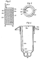
- the construction is shown in more detail in Figs. 2 and 3.
- the heat exchanger is made up of a single pipe which consists of two separate parts, namely an inner part 12a and an outer part 12b respectively. Both these parts are coiled in helical form in left-hand twist and right-hand twist respectively. Between the two parts there is a gap 12c. Between it and the outer and inner wall respectively of the vertical cylinder space 11, that is to say the annular heat and gas exchange chamber, the heat exchanger forms further gaps 12d and 12e, respectively.
- the gap 10 and the heat and gas exchange chamber 11 formed above it are designed to be located between the centrally arranged gas and liquid inlet pipe 5 and an intermediate vessel 16 which is open at the top.
- the gas which consists of oxygen or an oxygen mixture, when the device is used as an oxygenator, is supplied via an opening 17 and an inlet chamber 18 via a sterile filter (not shown) and further ducts into the annular space 7 in the inlet pipe 6.
- a sterile filter not shown
- the gas is then pressed out into the blood just where the gap 10 passes over into the widened cylinder space 11.
- the bubble formation is facilitated, in that the lower part of the space 11 is designed as a mixing chamber which is clear of the heat exchanger.
- the mixing process is improved further in the following heat exchange 12 with its gaps 12c, 12d, 12e.
- annular throttling gap 29 is shown schematically in Fig. 1 in the form of a spillway between the top edge of the vessel 16 and a lid 30 provided about the same.
- This lid is designed so as to be integral with the double-walled inlet pipe 5 and is connected in turn via seals 31 to an outer lid 32 comprising, among other things, the gas inlet chamber 18 and the sterile filter (not shown).
- this gap is replaced by the throttling ports 29a shown in Figs. 4-7, which will be described in more detail in connection with these figures.
- the gas mixture flows down through a gap 33 between the intermediate vessel 16 and a filter 34.
- the blood flows out through the filter 34 into blood collecting space 35, whilst the excess gas flows out instead through an outlet 36.
- the sampling nozzle 3 is intended for the sampling of venous blood. Via the sampling nozzle 37 and a pipe (not shown) it is possible instead to take samples of arterial blood owing to this pipe terminating down in the blood collecting space 35.
- the lower part of the bottom of this outer casing 39 is designed as an annular gap 41 with a base 42 sloping evenly towards the bottom outlet 40.
- the construction as a whole is composed of a number of concentric vessels inserted into each other.
- the outermost of these is the outer casing 39.
- a "vessel" formed of the filter 34 which is limited at the bottom by a base ring 43 and at the top by a fixing ring 44.
- the filter is fixed to the outside of the vessel 16 described above as the intermediate vessel.
- the inlet pipe 5 designed as a double-walled vessel.
- the base ring 43 and the fixing ring 44 are designed so that the filter 34 forms an angle against the outer wall of the vessel 16. Through this arrangement a conical space 46 is formed for the collection of the gas and liquid mixture before the same is passed through the filter 34. In this way the blood is made in the first place to pass through the lower part of the filter and to make use only at higher flow also of the upper parts of the filter 34.
- Numeral 45 designates an inlet nozzle intended for the supply of medicine, heparin or other additions to the mixture of gas and blood before the same passes the filter 34.
- the holes 20 it may be said that in a preferred embodiment they are constituted of a number of approximately 100 with an accurately defined diameter. This can be made to be practically exactly 25, for example, with the help of a laser technique. With a length of the holes of approximately 3 mm it was found that air will flow through all the holes, even at a gas flow as low as 0.75 litre per minute.
- the gap 10 is approximately 3 mm, which provides a good mixture at a standard blood flow of between 2 and 6 litre per minute.
- the device may also be used at higher as well as at lower flow.
- Numeral 47 finally designates a number of caps for the closing of different openings of the oxygenator.
- the vessel shown in Figs. 4 and 5 correspond in principle to the vessel 16 in Fig. 1. It has been somewhat modified, however, and for this reason the same reference designations have been used, but with the addition of a small a.
- the vessel is thus designated 16a and the throttling ports, which replace the gap 29, are designated 29a.
- Numeral 48a designates three ribs which together define the size of the gap, corresponding to the gap 12d formed between the heat exchanger 12 and the vessel 16a.
- Three shoulders 49a define the lower limit of the heat exchanger or the upper limit of the mixing chamber corresponding to the chamber 19 in Fig. 1.
- Numeral 50a designates a point which is designated so as to ensure that the blood is deflected smoothly from a flow directed vertically downwards to one directed upwards.
- the intermediate stage 51a is provided with thickened portions so as to facilitate the outflow of the plastic when the vessel 16a and the lid 52a attached are manufactured by injection moulding.
- the ports 29a are of a double-curved shape. This shape is very important, as it ensures that the blood is handled gently in spite of these ports being subjected to a throttling.
Landscapes
- Health & Medical Sciences (AREA)
- Heart & Thoracic Surgery (AREA)
- Vascular Medicine (AREA)
- Hematology (AREA)
- Animal Behavior & Ethology (AREA)
- Engineering & Computer Science (AREA)
- Anesthesiology (AREA)
- Biomedical Technology (AREA)
- Emergency Medicine (AREA)
- Life Sciences & Earth Sciences (AREA)
- Veterinary Medicine (AREA)
- General Health & Medical Sciences (AREA)
- Public Health (AREA)
- Urology & Nephrology (AREA)
- Cardiology (AREA)
- External Artificial Organs (AREA)
- Gas Separation By Absorption (AREA)
Abstract
Description
- The present invention relates to a device for the transfer of one or more substances between a gas and a liquid, the gas being introduced into the liquid in the form of bubbles, from which the said substances are transferred to the fluid, whereafter the excess gas is removed together with any substances transferred from the liquid to the gas.
- The device in accordance with the invention is intended in the first place to be used for the oxygenation of blood, that is to say as an oxygenator. It is clear, however, to those versed in the art that the construction in accordance with the invention can also be used for many other purposes, that is to say substantially wherever substances from a gas are to be made to react with or to dissolve in a liquid or else if the substances are to be exchanged between gases and liquids.
- Insofar as oxygenators are concerned, three main types can be distinguished. The oldest is probably the type where a blood film is formed in direct contact with an atmosphere containing oxygen. In a second type the oxygen is made instead to diffuse through a semipermeable membrane from an atmosphere containing oxygen on the one side of the membrane to the blood on the other side. The third type, to which belongs the device in accordance with the invention, is known under the name of bubble oxygenator. In this type the gas bubbles containing oxygen are introduced directly into the blood so as directly to act on the same. After the desired action the excess gas is removed together with carbon dioxide withdrawn from the blood.
- Examples of constructions of the last mentioned type, that is to say of bubble oxygenators, are shown for example in the following US patent specifications: 3 175 555, 2 934 067, 3 545 937, 4073622, 3468631, 3488158, 3615238, 4 058 369, 3578411, 3291 568, 4 033 724, 3 827 860, 3853479, 4 067 696, 4 065 264, 4 138 464, 4 138 288.
- More particularly, the present invention constitutes a further development of the device according to EP-A-0 035 266, published after the priority date of the present application.
- Reference is finally made to US―A―4 261 951 describing an oxygenator essentially corresponding to the preamble of our following main claim and US―A―4 158 693 describing a heat exchanger similar to the one used in a preferred embodiment of the present invention.
- The device in accordance with the invention comprises an annular heat and gas exchange chamber designed for vertical placing and having a gas inlet at the lower end of this chamber and a heat exchanger arranged above this inlet and wherein the heat and gas exchange chamber is terminated at the top by a number of ports distributed evenly around the periphery, and is characterized in that the heat and gas exchange chamber is formed between an inner gas and liquid inlet pipe and a vessel arranged outside the same which is open at the top, the ports being constituted of recesses in the top edge of this vessel, which is preferably arranged so as to be in contact against a lid provided over the vessel and the said pipe. Through this arrangement a very uniform and homogeneous flow around the whole periphery of the heat and gas exchange chamber is achieved. In this manner a very good heat transfer or gas exchange is obtained.
- To prevent any damage to the blood when the device is used as an oxygenator in connection with the throttling, the ports may be approximately rounded off evenly by a double-curved shape.
- In a preferred embodiment of the invention, the device comprises an outer casing arranged outside the said vessel, which between itself and the vessel forms a skimming chamber with a filter for the final breaking down of the gas bubbles. This filter is appropriately arranged obliquely so that between the said vessel and the filter a wedge-shaped collecting space for the liquid widening upwards is formed, into which open the said ports. This construction has proved to be suitable from a point of view of assembly as well as from a point of view of efficiency.
- The heat exchanger is suitably shorter than the heat and gas exchange chamber and may be separated from the gas inlet by means of a mixing chamber. By this arrangement the bubbles can be formed in this mixing chamber irrespectively of the design of the heat exchanger.
- The gas inlet is preferably constituted of a plurality of holes of substantially the same size distributed evenly around the periphery of the chamber for the formation of bubbles which are partly broken down in a plurality of gaps formed by the heat exchanger in the heat and gas exchange chamber, to be broken down further, subsequently, in the said ports.
- It should be mentioned that the transfer of carbon dioxide is normally considered to be improved by large bubbles whilst the transfer of oxygen is considered to be at its most effective by means of small bubbles.
- The heat exchanger may consist of two pipe parts coiled in helical manner, one of which is coiled outside the other, these two parts being separated by a first gap and forming a second and a third gap, respectively between themselves and the inner and outer wall respectively of the annular heat and gas exchange chamber. The two parts of the heat exchanger coiled in helical manner suitably constitute parts of one and the same pipe, whose ends are threaded through the lid provided above the heat and gas exchange chamber. It has been found that this heat exchanger gives a very good heat transfer, at the same time as it facilitates the mixing process owing to the gas bubbles being partly transformed and/or broken down. At the same time the construction is completely free of leakage problems and is very suitable from a point of view of installation.
- As mentioned already, the construction in accordance with the invention is used chiefly as a so-called oxygenator, the said liquid being constituted of blood and the said gas being constituted of oxygen or an oxygen mixture from which oxygen is transferred to the blood and to which carbon dioxide is transferred from the blood. The invention is described, therefore, in the following with reference to such a construction, made up of a number of concentric vessels arranged concentrically inside one another which can easily be sealed off in relation to each other.
-
- Fig. 1 shows a longitudinal section through an oxygenator which falls outside the scope of the present invention but may easily be modified in accordance with the invention.
- Figs. 2 and 3 show a side view and an end view respectively of a heat exchanger forming part of the oxygenator.
- Fig. 4 shows a longitudinal section through an intermediate vessel forming part of an oxygenator according to the present invention.
- Fig. 5 shows an end view of the corresponding vessel seen from the open upper end of the same.
- Figs. 6 and 7 finally show a section along the line VI-VI and a section perpendicular thereto through a throttling port provided at the top edge of the vessel shown in Fig. 4 and 5, respectively.
- In the embodiment shown as an example venous blood is supplied from a patient to the
inlet nozzle 1 arranged at the top. This nozzle together with a second inlet nozzle 2 and a sampling nozzle 3 is arranged on a branch pipe 4 which is freely rotatable in respect of the rest of the oxygenator. This branch pipe 4 is threaded onto a double-walled inlet pipe 5 arranged centrally in the oxygenator which contains an inner centralliquid inlet duct 6 and an outer annular gap 7 for the gas supply. Between the inlet pipe 5 and the branch pipe 4 apacking 8 is provided. Thus the blood is caused to flow vertically down through theduct 6 and via asmooth passage 9 into a narrowannular gap 10. This gap subsequently passes into a widened annularvertical cylinder space 11 which contains aheat exchanger 12 and forms a heat and gas exchange chamber. Theheat exchanger 12 is provided with aliquid inlet 13 and aliquid outlet 14. The construction is shown in more detail in Figs. 2 and 3. As is evident from these figures the heat exchanger is made up of a single pipe which consists of two separate parts, namely aninner part 12a and anouter part 12b respectively. Both these parts are coiled in helical form in left-hand twist and right-hand twist respectively. Between the two parts there is agap 12c. Between it and the outer and inner wall respectively of thevertical cylinder space 11, that is to say the annular heat and gas exchange chamber, the heat exchanger formsfurther gaps - The
gap 10 and the heat andgas exchange chamber 11 formed above it are designed to be located between the centrally arranged gas and liquid inlet pipe 5 and anintermediate vessel 16 which is open at the top. - The gas, which consists of oxygen or an oxygen mixture, when the device is used as an oxygenator, is supplied via an
opening 17 and aninlet chamber 18 via a sterile filter (not shown) and further ducts into the annular space 7 in theinlet pipe 6. Through a series ofholes 20 which are evenly distributed along the periphery of thegap 10 at the upper end of the latter, the gas is then pressed out into the blood just where thegap 10 passes over into the widenedcylinder space 11. Through this arrangement a very effective mixture of blood and gas is achieved. The bubble formation is facilitated, in that the lower part of thespace 11 is designed as a mixing chamber which is clear of the heat exchanger. The mixing process is improved further in the followingheat exchange 12 with itsgaps - The mixture of gas and liquid thus flows vertically upwards in the said gaps. In the upper end of the heat exchanger an
annular throttling gap 29 is shown schematically in Fig. 1 in the form of a spillway between the top edge of thevessel 16 and alid 30 provided about the same. This lid is designed so as to be integral with the double-walled inlet pipe 5 and is connected in turn viaseals 31 to an outer lid 32 comprising, among other things, thegas inlet chamber 18 and the sterile filter (not shown). In accordance with the invention, however, this gap is replaced by thethrottling ports 29a shown in Figs. 4-7, which will be described in more detail in connection with these figures. - From the
spillway 29 or thethrottling ports 29a the gas mixture flows down through agap 33 between theintermediate vessel 16 and afilter 34. The blood flows out through thefilter 34 intoblood collecting space 35, whilst the excess gas flows out instead through anoutlet 36. - The sampling nozzle 3 is intended for the sampling of venous blood. Via the
sampling nozzle 37 and a pipe (not shown) it is possible instead to take samples of arterial blood owing to this pipe terminating down in theblood collecting space 35. - The
intermediate vessel 16 with the inlet pipe 5 arranged therein and thefilter 34 arranged outside the same, are enclosed in anouter casing 39 comprising a bottom outlet 40 for the separated liquid phase. The lower part of the bottom of thisouter casing 39 is designed as anannular gap 41 with a base 42 sloping evenly towards the bottom outlet 40. - It can be said that the construction as a whole is composed of a number of concentric vessels inserted into each other. The outermost of these is the
outer casing 39. Into this is inserted a "vessel" formed of thefilter 34 which is limited at the bottom by abase ring 43 and at the top by a fixingring 44. With the help of thering 44 the filter is fixed to the outside of thevessel 16 described above as the intermediate vessel. Into the latter is then inserted the inlet pipe 5 designed as a double-walled vessel. - The
base ring 43 and the fixingring 44 are designed so that thefilter 34 forms an angle against the outer wall of thevessel 16. Through this arrangement aconical space 46 is formed for the collection of the gas and liquid mixture before the same is passed through thefilter 34. In this way the blood is made in the first place to pass through the lower part of the filter and to make use only at higher flow also of the upper parts of thefilter 34. -
Numeral 45 designates an inlet nozzle intended for the supply of medicine, heparin or other additions to the mixture of gas and blood before the same passes thefilter 34. - With regard to the
holes 20 it may be said that in a preferred embodiment they are constituted of a number of approximately 100 with an accurately defined diameter. This can be made to be practically exactly 25, for example, with the help of a laser technique. With a length of the holes of approximately 3 mm it was found that air will flow through all the holes, even at a gas flow as low as 0.75 litre per minute. - In this preferred embodiment the
gap 10 is approximately 3 mm, which provides a good mixture at a standard blood flow of between 2 and 6 litre per minute. However, the device may also be used at higher as well as at lower flow. -
Numeral 47 finally designates a number of caps for the closing of different openings of the oxygenator. - The vessel shown in Figs. 4 and 5 correspond in principle to the
vessel 16 in Fig. 1. It has been somewhat modified, however, and for this reason the same reference designations have been used, but with the addition of a small a. The vessel is thus designated 16a and the throttling ports, which replace thegap 29, are designated 29a. Numeral 48a designates three ribs which together define the size of the gap, corresponding to thegap 12d formed between theheat exchanger 12 and thevessel 16a. Three shoulders 49a define the lower limit of the heat exchanger or the upper limit of the mixing chamber corresponding to thechamber 19 in Fig. 1. Numeral 50a designates a point which is designated so as to ensure that the blood is deflected smoothly from a flow directed vertically downwards to one directed upwards. Theintermediate stage 51a is provided with thickened portions so as to facilitate the outflow of the plastic when thevessel 16a and thelid 52a attached are manufactured by injection moulding. - As is evident from Figs. 6 and 7, the
ports 29a are of a double-curved shape. This shape is very important, as it ensures that the blood is handled gently in spite of these ports being subjected to a throttling. - Naturally the invention is not limited to the embodiment described above, but can be varied within the scope of the subsequent claims. The individual shape of the components present, for example, may be varied within wide limits. See also EP-A-0 069 237 submitted at the same time and the above-mentioned EP-A-0 035 266.
Claims (7)
Priority Applications (1)
| Application Number | Priority Date | Filing Date | Title |
|---|---|---|---|
| AT82104971T ATE16351T1 (en) | 1981-07-07 | 1982-06-07 | DEVICE FOR TRANSFERRING ONE OR MORE SUBSTANCES BETWEEN A GAS AND A LIQUID. |
Applications Claiming Priority (2)
| Application Number | Priority Date | Filing Date | Title |
|---|---|---|---|
| SE8104219A SE423678B (en) | 1981-07-07 | 1981-07-07 | DEVICE FOR TRANSFER OF ONE OR MULTIPLE SUBSTANCES BETWEEN A GAS AND A FLUID |
| SE8104219 | 1981-07-07 |
Publications (2)
| Publication Number | Publication Date |
|---|---|
| EP0069236A1 EP0069236A1 (en) | 1983-01-12 |
| EP0069236B1 true EP0069236B1 (en) | 1985-11-06 |
Family
ID=20344214
Family Applications (1)
| Application Number | Title | Priority Date | Filing Date |
|---|---|---|---|
| EP82104971A Expired EP0069236B1 (en) | 1981-07-07 | 1982-06-07 | A device for the transfer of one or more substances between a gas and a liquid |
Country Status (6)
| Country | Link |
|---|---|
| US (1) | US4533516A (en) |
| EP (1) | EP0069236B1 (en) |
| JP (1) | JPS5815864A (en) |
| AT (1) | ATE16351T1 (en) |
| DE (1) | DE3267260D1 (en) |
| SE (1) | SE423678B (en) |
Families Citing this family (12)
| Publication number | Priority date | Publication date | Assignee | Title |
|---|---|---|---|---|
| AU573667B2 (en) * | 1983-12-27 | 1988-06-16 | Baxter Travenol Laboratories Inc. | Blood heat exchanger |
| JPS60182966U (en) * | 1984-05-14 | 1985-12-04 | 木村 茂雄 | A device that can shave long hair with an electric beard shaving machine |
| JPH0342927Y2 (en) * | 1987-02-09 | 1991-09-09 | ||
| JPH06102467B2 (en) * | 1988-02-03 | 1994-12-14 | テルモ株式会社 | Plug body and medical device with a plug body including the plug body |
| US5270004A (en) * | 1989-10-01 | 1993-12-14 | Minntech Corporation | Cylindrical blood heater/oxygenator |
| US5266265A (en) * | 1992-10-08 | 1993-11-30 | Baxter International, Inc. | Modular disposable blood oxygenator/heat exchanger with durable heat source component, selectively including rotary or ventricular blood pump, venous reservoir, and auxiliary heat exchange component |
| US6322546B1 (en) * | 1999-10-28 | 2001-11-27 | Jostra Bentley Inc. | Fluid control conduit |
| US6682698B2 (en) | 2001-08-23 | 2004-01-27 | Michigan Critical Care Consultants, Inc. | Apparatus for exchanging gases in a liquid |
| US8906300B2 (en) | 2011-08-11 | 2014-12-09 | The University Of Kentucky Research Foundation | Even perfusion pump-integrated blood oxygenator |
| US8777832B1 (en) | 2013-03-14 | 2014-07-15 | The University Of Kentucky Research Foundation | Axial-centrifugal flow catheter pump for cavopulmonary assistance |
| JP6461975B2 (en) | 2013-12-23 | 2019-01-30 | ユニバーシティ・オブ・メリーランド・ボルティモアUniversity Of Maryland, Baltimore | Blood oxygenator |
| CN112618829B (en) * | 2020-12-30 | 2022-11-04 | 东莞科威医疗器械有限公司 | Hollow fiber tube diversion temperature changing device and oxygenator for ECMO |
Family Cites Families (6)
| Publication number | Priority date | Publication date | Assignee | Title |
|---|---|---|---|---|
| US4138464A (en) * | 1976-05-10 | 1979-02-06 | Lewin John E | Blood oxygenator with integral heat exchanger |
| US4140635A (en) * | 1977-04-13 | 1979-02-20 | Esmond William G | Purification device |
| US4180896A (en) * | 1977-12-29 | 1980-01-01 | Texas Medical Products, Inc. | Blood oxygenator assembly method |
| US4158693A (en) * | 1977-12-29 | 1979-06-19 | Texas Medical Products, Inc. | Blood oxygenator |
| FR2418651A1 (en) * | 1978-03-02 | 1979-09-28 | Dso Metalchim | BLOOD OXYGENATION APPARATUS |
| WO1981002836A1 (en) * | 1980-03-03 | 1981-10-15 | Gambro Ab | A device for the transfer of one or more substances between a gas and a liquid |
-
1981
- 1981-07-07 SE SE8104219A patent/SE423678B/en unknown
-
1982
- 1982-06-07 AT AT82104971T patent/ATE16351T1/en not_active IP Right Cessation
- 1982-06-07 DE DE8282104971T patent/DE3267260D1/en not_active Expired
- 1982-06-07 EP EP82104971A patent/EP0069236B1/en not_active Expired
- 1982-07-06 US US06/395,283 patent/US4533516A/en not_active Expired - Fee Related
- 1982-07-06 JP JP57117655A patent/JPS5815864A/en active Pending
Also Published As
| Publication number | Publication date |
|---|---|
| ATE16351T1 (en) | 1985-11-15 |
| EP0069236A1 (en) | 1983-01-12 |
| SE423678B (en) | 1982-05-24 |
| JPS5815864A (en) | 1983-01-29 |
| US4533516A (en) | 1985-08-06 |
| DE3267260D1 (en) | 1985-12-12 |
Similar Documents
| Publication | Publication Date | Title |
|---|---|---|
| EP0035266B1 (en) | A device for the transfer of one or more substances between a gas and a liquid | |
| US4469659A (en) | Sampling device for blood oxygenator | |
| US5058661A (en) | Heat exchanger with leakage collector | |
| USRE36774E (en) | Cylindrical blood heater/oxygenator | |
| CA1191415A (en) | Rigid shell expansible blood reservoir, heater and hollow fiber membrane oxygenator assembly | |
| US4818490A (en) | Integral blood oxygenator | |
| US4219426A (en) | Dialysis device | |
| EP0876170B1 (en) | Blood oxygenator with heat exchanger | |
| EP0003495B1 (en) | A device for the diffusion of substances between two fluids separated by a semipermeable membrane | |
| US5823987A (en) | Compact membrane-type blood oxygenator with concentric heat exchanger | |
| EP0069236A1 (en) | A device for the transfer of one or more substances between a gas and a liquid | |
| US4256692A (en) | Membrane oxygenator | |
| US4058369A (en) | Oxygenator | |
| US5906741A (en) | Outlet manifold for blood oxygenator apparatus | |
| US5922202A (en) | Inlet manifold for blood oxygenator apparatus | |
| JPS63503044A (en) | Device for exchanging ions, molecules, gases, liquids and/or heat between fluids | |
| EP0069237B1 (en) | A device for the transfer of one or more substances between a gas and a liquid | |
| EP0548065A1 (en) | CYLINDRICAL BLOOD WARMER AND BLOOD OXYGENATOR. | |
| US5858233A (en) | Transition manifold for blood oxygenator apparatus | |
| JP3284568B2 (en) | Inlet header for oxygenator and oxygenator using it | |
| US4248828A (en) | Oxygenator | |
| JPH041950Y2 (en) | ||
| CN216798373U (en) | Hemodialysis shell body convenient to promote hemodialysis | |
| SU937516A1 (en) | Fermentation apparatus for conducting process with immobolized enzymes | |
| AU4622601A (en) | Blood oxygenator with heat exchanger |
Legal Events
| Date | Code | Title | Description |
|---|---|---|---|
| PUAI | Public reference made under article 153(3) epc to a published international application that has entered the european phase |
Free format text: ORIGINAL CODE: 0009012 |
|
| AK | Designated contracting states |
Designated state(s): AT BE CH DE FR GB IT LI LU NL |
|
| 17P | Request for examination filed |
Effective date: 19830527 |
|
| RAP1 | Party data changed (applicant data changed or rights of an application transferred) |
Owner name: GAMBRO CARDIO AB |
|
| ITF | It: translation for a ep patent filed | ||
| GRAA | (expected) grant |
Free format text: ORIGINAL CODE: 0009210 |
|
| AK | Designated contracting states |
Designated state(s): AT BE CH DE FR GB IT LI LU NL |
|
| PG25 | Lapsed in a contracting state [announced via postgrant information from national office to epo] |
Ref country code: AT Effective date: 19851106 |
|
| REF | Corresponds to: |
Ref document number: 16351 Country of ref document: AT Date of ref document: 19851115 Kind code of ref document: T |
|
| REF | Corresponds to: |
Ref document number: 3267260 Country of ref document: DE Date of ref document: 19851212 |
|
| ET | Fr: translation filed | ||
| PG25 | Lapsed in a contracting state [announced via postgrant information from national office to epo] |
Ref country code: LU Free format text: LAPSE BECAUSE OF NON-PAYMENT OF DUE FEES Effective date: 19860630 |
|
| PGFP | Annual fee paid to national office [announced via postgrant information from national office to epo] |
Ref country code: NL Payment date: 19860630 Year of fee payment: 5 |
|
| PLBE | No opposition filed within time limit |
Free format text: ORIGINAL CODE: 0009261 |
|
| STAA | Information on the status of an ep patent application or granted ep patent |
Free format text: STATUS: NO OPPOSITION FILED WITHIN TIME LIMIT |
|
| 26N | No opposition filed | ||
| PG25 | Lapsed in a contracting state [announced via postgrant information from national office to epo] |
Ref country code: LI Effective date: 19870630 Ref country code: CH Effective date: 19870630 |
|
| BERE | Be: lapsed |
Owner name: GAMBRO CARDIO A.B. Effective date: 19870630 |
|
| PG25 | Lapsed in a contracting state [announced via postgrant information from national office to epo] |
Ref country code: NL Effective date: 19880101 |
|
| NLV4 | Nl: lapsed or anulled due to non-payment of the annual fee | ||
| PG25 | Lapsed in a contracting state [announced via postgrant information from national office to epo] |
Ref country code: FR Free format text: LAPSE BECAUSE OF NON-PAYMENT OF DUE FEES Effective date: 19880226 |
|
| REG | Reference to a national code |
Ref country code: CH Ref legal event code: PL |
|
| GBPC | Gb: european patent ceased through non-payment of renewal fee | ||
| REG | Reference to a national code |
Ref country code: FR Ref legal event code: ST |
|
| PG25 | Lapsed in a contracting state [announced via postgrant information from national office to epo] |
Ref country code: GB Effective date: 19881121 |
|
| PG25 | Lapsed in a contracting state [announced via postgrant information from national office to epo] |
Ref country code: BE Effective date: 19890630 |
|
| PGFP | Annual fee paid to national office [announced via postgrant information from national office to epo] |
Ref country code: DE Payment date: 19910722 Year of fee payment: 10 |
|
| PG25 | Lapsed in a contracting state [announced via postgrant information from national office to epo] |
Ref country code: DE Effective date: 19930302 |