EP0068621B1 - Device for cutting a paper or other record medium - Google Patents
Device for cutting a paper or other record medium Download PDFInfo
- Publication number
- EP0068621B1 EP0068621B1 EP82302558A EP82302558A EP0068621B1 EP 0068621 B1 EP0068621 B1 EP 0068621B1 EP 82302558 A EP82302558 A EP 82302558A EP 82302558 A EP82302558 A EP 82302558A EP 0068621 B1 EP0068621 B1 EP 0068621B1
- Authority
- EP
- European Patent Office
- Prior art keywords
- cutter blade
- cutting
- blade
- cam
- support member
- Prior art date
- Legal status (The legal status is an assumption and is not a legal conclusion. Google has not performed a legal analysis and makes no representation as to the accuracy of the status listed.)
- Expired
Links
- 238000005520 cutting process Methods 0.000 title claims description 32
- 239000000463 material Substances 0.000 claims description 11
- 230000000694 effects Effects 0.000 claims description 10
- 239000004744 fabric Substances 0.000 description 3
- 230000007257 malfunction Effects 0.000 description 2
- 239000002184 metal Substances 0.000 description 2
- 230000005540 biological transmission Effects 0.000 description 1
- 238000000034 method Methods 0.000 description 1
Images


Classifications
-
- B—PERFORMING OPERATIONS; TRANSPORTING
- B41—PRINTING; LINING MACHINES; TYPEWRITERS; STAMPS
- B41J—TYPEWRITERS; SELECTIVE PRINTING MECHANISMS, i.e. MECHANISMS PRINTING OTHERWISE THAN FROM A FORME; CORRECTION OF TYPOGRAPHICAL ERRORS
- B41J11/00—Devices or arrangements of selective printing mechanisms, e.g. ink-jet printers or thermal printers, for supporting or handling copy material in sheet or web form
- B41J11/66—Applications of cutting devices
- B41J11/70—Applications of cutting devices cutting perpendicular to the direction of paper feed
-
- B—PERFORMING OPERATIONS; TRANSPORTING
- B26—HAND CUTTING TOOLS; CUTTING; SEVERING
- B26D—CUTTING; DETAILS COMMON TO MACHINES FOR PERFORATING, PUNCHING, CUTTING-OUT, STAMPING-OUT OR SEVERING
- B26D7/00—Details of apparatus for cutting, cutting-out, stamping-out, punching, perforating, or severing by means other than cutting
- B26D7/22—Safety devices specially adapted for cutting machines
- B26D7/24—Safety devices specially adapted for cutting machines arranged to disable the operating means for the cutting member
-
- Y—GENERAL TAGGING OF NEW TECHNOLOGICAL DEVELOPMENTS; GENERAL TAGGING OF CROSS-SECTIONAL TECHNOLOGIES SPANNING OVER SEVERAL SECTIONS OF THE IPC; TECHNICAL SUBJECTS COVERED BY FORMER USPC CROSS-REFERENCE ART COLLECTIONS [XRACs] AND DIGESTS
- Y10—TECHNICAL SUBJECTS COVERED BY FORMER USPC
- Y10T—TECHNICAL SUBJECTS COVERED BY FORMER US CLASSIFICATION
- Y10T83/00—Cutting
- Y10T83/869—Means to drive or to guide tool
- Y10T83/8719—With transmission yieldable on overload
-
- Y—GENERAL TAGGING OF NEW TECHNOLOGICAL DEVELOPMENTS; GENERAL TAGGING OF CROSS-SECTIONAL TECHNOLOGIES SPANNING OVER SEVERAL SECTIONS OF THE IPC; TECHNICAL SUBJECTS COVERED BY FORMER USPC CROSS-REFERENCE ART COLLECTIONS [XRACs] AND DIGESTS
- Y10—TECHNICAL SUBJECTS COVERED BY FORMER USPC
- Y10T—TECHNICAL SUBJECTS COVERED BY FORMER US CLASSIFICATION
- Y10T83/00—Cutting
- Y10T83/869—Means to drive or to guide tool
- Y10T83/8776—Constantly urged tool or tool support [e.g., spring biased]
-
- Y—GENERAL TAGGING OF NEW TECHNOLOGICAL DEVELOPMENTS; GENERAL TAGGING OF CROSS-SECTIONAL TECHNOLOGIES SPANNING OVER SEVERAL SECTIONS OF THE IPC; TECHNICAL SUBJECTS COVERED BY FORMER USPC CROSS-REFERENCE ART COLLECTIONS [XRACs] AND DIGESTS
- Y10—TECHNICAL SUBJECTS COVERED BY FORMER USPC
- Y10T—TECHNICAL SUBJECTS COVERED BY FORMER US CLASSIFICATION
- Y10T83/00—Cutting
- Y10T83/869—Means to drive or to guide tool
- Y10T83/8776—Constantly urged tool or tool support [e.g., spring biased]
- Y10T83/8785—Through return [noncutting] stroke
- Y10T83/8786—Oscillating tool
-
- Y—GENERAL TAGGING OF NEW TECHNOLOGICAL DEVELOPMENTS; GENERAL TAGGING OF CROSS-SECTIONAL TECHNOLOGIES SPANNING OVER SEVERAL SECTIONS OF THE IPC; TECHNICAL SUBJECTS COVERED BY FORMER USPC CROSS-REFERENCE ART COLLECTIONS [XRACs] AND DIGESTS
- Y10—TECHNICAL SUBJECTS COVERED BY FORMER USPC
- Y10T—TECHNICAL SUBJECTS COVERED BY FORMER US CLASSIFICATION
- Y10T83/00—Cutting
- Y10T83/869—Means to drive or to guide tool
- Y10T83/8798—With simple oscillating motion only
- Y10T83/8804—Tool driver movable relative to tool support
- Y10T83/8805—Cam or eccentric revolving about fixed axis
-
- Y—GENERAL TAGGING OF NEW TECHNOLOGICAL DEVELOPMENTS; GENERAL TAGGING OF CROSS-SECTIONAL TECHNOLOGIES SPANNING OVER SEVERAL SECTIONS OF THE IPC; TECHNICAL SUBJECTS COVERED BY FORMER USPC CROSS-REFERENCE ART COLLECTIONS [XRACs] AND DIGESTS
- Y10—TECHNICAL SUBJECTS COVERED BY FORMER USPC
- Y10T—TECHNICAL SUBJECTS COVERED BY FORMER US CLASSIFICATION
- Y10T83/00—Cutting
- Y10T83/869—Means to drive or to guide tool
- Y10T83/8798—With simple oscillating motion only
- Y10T83/8812—Cutting edge in radial plane
- Y10T83/8815—With guide means for the cutting member
Definitions
- the present invention relates to a device for cutting a paper or other record material, the device being adapted for use with a printer.
- a cutting device is known from US-A-369,473 comprising a first cutter blade; a second cutter blade which is cooperable with the first cutter blade so as to cut material; a support member for supporting the second cutter blade for angular movement, the second cutter blade having an engagement surface which normally engages the support member so that the latter acts as a fulcrum for the second cutter blade; urging means which urge the engagement surface towards a predetermined position with respect to the support member; driving means for driving the second cutter blade towards the first cutter blade in an operative stroke to effect cutting, and a return spring for returning the second cutter blade to a ready position after the second cutter blade has effected the said operative stroke.
- the cutting device of US-A-369,473 was designed merely for cutting a button hole in cloth and is a hand operated machine.
- the cloth is cut by the cooperation between dies located in a common vertical plane on opposite sides of the cloth, cutting being effected by moving the discs towards each other.
- the device is power operated and the blades are constituted by a fixed blade across which the other blade is moved, the presence of the foreign material will not be detected before considerable damage is done and the device may well then be not only damaged but also jammed.
- a cutting device for cutting paper or other record medium emanating from a printer comprising a fixed first cutter blade; a second cutter blade which is cooperable with the first cutter blade so as to cut the record medium; a support member for supporting the second cutter blade for angular movement, the second cutter blade having an engagement surface resiliently urged by resilient urging means into engagement with the support member, the latter thus providing a fulcrum for the second cutter blade; power operated driving means for driving the second cutter blade towards the first cutter blade in an operative stroke to effect cutting, and a return spring for returning the second cutter blade to a pre-cut position after the second cutter blade has effected the said operative stroke, whereby the first cutter blade is a fixed blade across which the second cutter blade is moved by power operated driving means during the said operative stroke, the second cutter blade being mounted for movement against said resilient urging means to a position in which the engagement surface is released from the fulcrum presented by the support member, such that should the second cutter blade encounter undue resistance during its
- the second cutter blade is movable to a position in which the engagement surface is out of engagement with the support member, the power operation of the device will not damage the latter even if foreign material is present between the blades, while jamming is also avoided.
- the driving means may comprise a rotary cam which is disposed between and engageable with first and second parts of a drive lever which engages the second cutter blade, the arrangement being such that, in normal operation, the cam operatively engages only the said first part to effect operation of the second cutter blade, but that if the return spring alone is unable to return the second cutter blade to the pre-cut position, the cam operatively engages the said second part so as to effect such return.
- the arrangement may be such that during one complete revolution of the cam, the second cutter blade is moved from and returned to the pre-cut position so as to effect a cutting operation.
- Presser means may be provided for pressing the second cutter blade against the first cutter blade during cutting of the material.
- the first cutter blade and/or the second cutter blade may be so formed that the material is incompletely or discontinuously cut or perforated.
- the said engagement surface is preferably an arcuate surface of a recess in the movable second cutter blade.
- the invention provides an inexpensive and safe device for cutting a sheet of record paper used in a printer.
- a device for cutting a paper or other record medium and which is associated with a printer comprises a movable cutter blade 1, a cutter shaft or support member 2 about which the movable cutter blade 1 is angularly movable, a presser spring 3 for preventing the movable cutter blade 1 from moving upwardly, a return spring 4 for returning the movable cutter blade 1 to a pre-cut position after it has been actuated, and a fixed cutter blade 5 across which the movable cutter blade 1 is movable so as to cut a sheet of record paper 14.
- a release spring 6 has one end secured to a frame 12, its other end engaging the movable cutter blade 1. The release spring 6 is supported on a release spring pin 7.
- the movable cutter blade 1 has a recess therein provided with an arcuate engagement surface 1a which normally engages the support member 2 so that the latter acts as a fulcrum for the movable cutter blade 1, the release spring 6 urging the engagement surface 1a towards contact with the support member 2.
- the recess is so shaped, however, that the engagement surface 1a may move away from the support member 2 if, as described below, an undue load acts between the fixed cutter blade 5 and the movable cutter blade 1.
- the movable cutter blade 1 can be actuated by a cutter drive lever 8 which is rotatably mounted on a shaft 9 which is itself mounted in the frame 12.
- the frame 12 has an opening 13 for the passage therethrough of the sheet of record paper 14.
- the drive cam 10 In operation when power is transmitted from the power source (not shown) to the drive cam shaft 11, the drive cam 10, which is fixed to the drive cam shaft 11, starts rotating.
- the drive cam shaft 11 is arranged to be driven intermittently, e.g. by a spring-operated clutch controlled by an external signal for timed operation so as to cause the drive cam 10 to make one revolution.
- the drive cam 10 rotates clockwise, it moves into engagement with a flange portion 8-1 of the cutter drive lever 8 which is rotatably mounted on the shaft 9.
- the cutter drive lever 8 is therefore angularly moved in the direction of an arrow A, thus causing the movable cutter blade 1 to angularly move counter-clockwise about the fulcrum constituted by the support member 2.
- the movable cutter blade 1 thus moves across the fixed cutter blade 5 to cut off the sheet of record paper 14.
- the arrangement is such that, during one complete revolution of the cam 10, the movable cutter blade 1 is moved from and is returned to the pre-cut position shown in Figure 1 so as to effect a cutting operation.
- Actuation of the drive cam 10 and of the cutter drive lever 8 enables the movable cutter blade 1 to move across a cutting edge of the fixed cutter blade 5 while in contact therewith, thus severing the sheet of record paper 14.
- the release spring 6 presses the engagement surface 1a of the movable cutter blade 1 against the support member 2 with a force which is large enough to overcome the load imposed on the movable cutter blade 1 when the latter cuts off the sheet of record paper 14.
- the presser spring 3 holds the movable cutter blade 1 downwardly to maintain the movable and fixed cutter blades 1, 5 in mutual contact against the cutting load imposed by the sheet of record paper 14 while the movable cutter blade 1 is moving across the fixed cutter blade 5.
- the flange portion 8-1 of the drive lever 8 engages with a smaller-diameter cam surface of the drive cam 10 which is located past the maximum-diameter portion thereof, whereupon the return spring 4 causes the movable cutter blade 1 to angularly move the cutter lever 8 rapidly in the direction of an arrow B.
- the drive lever 8 and the movable cutter blade 1 are in their pre-cut position.
- the drive system will be protected when foreign matter such as a piece of metal enters between the movable cutter blade 1 and the fixed cutter blade 5 or when the movable cutter blade 1 and the fixed cutter blade 5 are stuck or locked against their mutual traversing movement. More specifically, operation of the drive system upon entrance of foreign matter between the movable cutter blade 1 and the fixed cutter blade 5 will now be described with reference to Figure 2. Actuation of the drive system for driving the parts to cut off the sheet of record paper is the same as that for severing the sheet of record paper 14 in normal conditions, and will not be described.
- the movable cutter blade 1 When, however, the movable cutter blade 1 hits foreign matter 15 as the movable cutter blade 1 moves across the fixed cutter blade 5 after the movable cutter blade 1 has started being actuated, the movable cutter blade 1 and the fixed cutter blade 5 may become stuck or locked and unable to cut off the sheet of record paper 14. In this case, the movable cutter blade 1 will be angularly displaced in the direction of the arrow A so that the engagement surface 1a is moved in a direction away from the support member 2. Thus the foreign matter 15 will then serve as a fulcrum for the movable cutter blade 1 which is pressed against the foreign matter 15 by the release spring 6, the support member 2 no longer constituting such a fulcrum.
- the cutter drive lever 8 is therefore able without damage to angularly move about the shaft 9 and to be operated by engagement with the cam surface of the drive cam 10, as in the normal process for cutting the sheet of record paper 14. Accordingly, the drive member 8, the movable cutter blade 1, the fixed cutter blade 5, and the other parts are prevented from undergoing any undue load or stress and hence from being broken or otherwise damaged.
- the movable cutter blade 1 is forcibly returned to its pre-cut position by bringing the cam surface of the drive cam 10 into engagement with a portion 8-2 of the cutter drive lever 8.
- the maximum diameter portion of the drive cam 10 is held against the flange portion 8-1 of the cutter drive lever 8 at the time of severing the sheet of record paper 14 under normal conditions, as illustrated in Figure 3.
- the drive cam 10 rotates in the direction of an arrow C simultaneously with completion of the severance of the record paper 14 until the flange portion 8-1 of the cutter drive lever 8 is caused, under the resiliency of the return spring 4, to engage the minimum-diameter portion of the drive cam 10, whereupon the movable cutter blade 1 and the cutter drive lever 8 are in the pre-cut position.
- the cutter drive lever 8 and the movable cutter blade 1 fail to return under the spring force of the return spring 4, and the flange portion 8-1 of the drive lever 8 does not engage the minimum-diameter portion of the drive cam 10 upon the latter's rotation in the direction of the arrow C.
- the movable cutter blade 1 and the cutter drive lever 8 can be returned under the biasing force of the return spring 4 alone after the sheet of record paper 14 has been cut off during a normal cutting operation.
- the drive lever 8 is returned to the pre-cut position before the maximum-diameter portion of the drive cam 10 engages the flange portion 8-2 of the cutter drive lever 8.
- the movable cutter blade 1 can be returned after the normal cutting operation without imposing an undue load on the drive cam 10 and the drive members.
- the movable cutter blade 1 has a continuous cutting edge along the portion thereof which is movable across the fixed cutter blade 5, the movable cutter blade 1 and/or the fixed cutter blade 5 may be partly slotted or grooved to allow the sheet of record paper 14 to remain partly uncut.
- This arrangement enables one to provide for easy handling of receipts in cash registers and the like.
- the device for cutting off a sheet of record paper described above is less costly and safer than previously known devices in that it has a reduced number of cutter blade parts and is simple in shape.
Landscapes
- Life Sciences & Earth Sciences (AREA)
- Forests & Forestry (AREA)
- Engineering & Computer Science (AREA)
- Mechanical Engineering (AREA)
- Handling Of Sheets (AREA)
- Details Of Cutting Devices (AREA)
Description
- The present invention relates to a device for cutting a paper or other record material, the device being adapted for use with a printer.
- Conventional devices of this kind have no satisfactory safety measures against the application of an undue or excessive load when foreign matter, such for example as a piece of metal, gets between movable and fixed cutter blades of the device, or when the movable and fixed cutter blades are stuck or locked. When the movable cutter blade or the fixed cutter blade is damaged, or the movable cutter blade is caused to malfunction, a paper feeder associated with the device tends to jam, with the result that a printing machine with which the device is also associated will be caused to malfunction.
- A cutting device is known from US-A-369,473 comprising a first cutter blade; a second cutter blade which is cooperable with the first cutter blade so as to cut material; a support member for supporting the second cutter blade for angular movement, the second cutter blade having an engagement surface which normally engages the support member so that the latter acts as a fulcrum for the second cutter blade; urging means which urge the engagement surface towards a predetermined position with respect to the support member; driving means for driving the second cutter blade towards the first cutter blade in an operative stroke to effect cutting, and a return spring for returning the second cutter blade to a ready position after the second cutter blade has effected the said operative stroke.
- The cutting device of US-A-369,473, however, was designed merely for cutting a button hole in cloth and is a hand operated machine. The cloth is cut by the cooperation between dies located in a common vertical plane on opposite sides of the cloth, cutting being effected by moving the discs towards each other.
- US-A-369,473 does not discuss what would happen if the blade carrying one of the dies was prevented from moving towards the other blade by striking foreign material, or if foreign material were present between the dies. Such an eventuality would have been extremely improbable and could not fail to be swiftly detected by the workman using the device who would merely have ceased to operate the handle of the device and would have removed the foreign material. Moreover, no jamming of the device could then have occurred.
- If, however, the device is power operated and the blades are constituted by a fixed blade across which the other blade is moved, the presence of the foreign material will not be detected before considerable damage is done and the device may well then be not only damaged but also jammed.
- According, therefore, to the present invention, there is provided a cutting device for cutting paper or other record medium emanating from a printer comprising a fixed first cutter blade; a second cutter blade which is cooperable with the first cutter blade so as to cut the record medium; a support member for supporting the second cutter blade for angular movement, the second cutter blade having an engagement surface resiliently urged by resilient urging means into engagement with the support member, the latter thus providing a fulcrum for the second cutter blade; power operated driving means for driving the second cutter blade towards the first cutter blade in an operative stroke to effect cutting, and a return spring for returning the second cutter blade to a pre-cut position after the second cutter blade has effected the said operative stroke, whereby the first cutter blade is a fixed blade across which the second cutter blade is moved by power operated driving means during the said operative stroke, the second cutter blade being mounted for movement against said resilient urging means to a position in which the engagement surface is released from the fulcrum presented by the support member, such that should the second cutter blade encounter undue resistance during its movement across the first cutter blade in the course of its operative stroke, the engagement surface then moves away from the support member so that the point of resistance subsequently provides a fulcrum point for the remaining operative stroke, thus preventing damage to the cutting device, the power operated driving means comprising means for automatically enforcing return of the second cutter blade to the pre-cut position whenever it has not been returned to its pre-cut position solely by the force of the return spring.
- In the case of the present invention, since the second cutter blade is movable to a position in which the engagement surface is out of engagement with the support member, the power operation of the device will not damage the latter even if foreign material is present between the blades, while jamming is also avoided.
- The driving means may comprise a rotary cam which is disposed between and engageable with first and second parts of a drive lever which engages the second cutter blade, the arrangement being such that, in normal operation, the cam operatively engages only the said first part to effect operation of the second cutter blade, but that if the return spring alone is unable to return the second cutter blade to the pre-cut position, the cam operatively engages the said second part so as to effect such return.
- The arrangement may be such that during one complete revolution of the cam, the second cutter blade is moved from and returned to the pre-cut position so as to effect a cutting operation.
- Presser means may be provided for pressing the second cutter blade against the first cutter blade during cutting of the material.
- The first cutter blade and/or the second cutter blade may be so formed that the material is incompletely or discontinuously cut or perforated.
- The said engagement surface is preferably an arcuate surface of a recess in the movable second cutter blade.
- In its preferred form, the invention provides an inexpensive and safe device for cutting a sheet of record paper used in a printer.
- The invention is illustrated, merely by way of example, in the accompanying drawings, in which:-
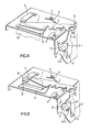
- Figure 1 is a perspective view of a device according to the present embodiment with the parts shown in a pre-cut position,
- Figure 2 is a perspective view of the device of Figure 1 showing a movable cutter blade subjected to an undue load,
- Figure 3 is a plan view of a cutter drive lever and a drive cam forming part of the device of Figure 1, the cutter drive lever and drive cam being shown in the positions in which they engage each other when a sheet of record paper is cut off,
- Figure 4 is a perspective view of the device of Figure 1 showing the way in which a movable cutter blade and the cutter drive lever are forcibly released from a locked condition, and
- Figure 5 is a perspective view of the device of Figure 1 showing the manner in which the movable cutter blade and the cutter drive lever are returned under normal conditions.
- Referring to the drawings, a device for cutting a paper or other record medium and which is associated with a printer (not shown) comprises a movable cutter blade 1, a cutter shaft or
support member 2 about which the movable cutter blade 1 is angularly movable, apresser spring 3 for preventing the movable cutter blade 1 from moving upwardly, areturn spring 4 for returning the movable cutter blade 1 to a pre-cut position after it has been actuated, and a fixedcutter blade 5 across which the movable cutter blade 1 is movable so as to cut a sheet ofrecord paper 14. Arelease spring 6 has one end secured to aframe 12, its other end engaging the movable cutter blade 1. Therelease spring 6 is supported on a release spring pin 7. The movable cutter blade 1 has a recess therein provided with an arcuate engagement surface 1a which normally engages thesupport member 2 so that the latter acts as a fulcrum for the movable cutter blade 1, therelease spring 6 urging the engagement surface 1a towards contact with thesupport member 2. The recess is so shaped, however, that the engagement surface 1a may move away from thesupport member 2 if, as described below, an undue load acts between the fixedcutter blade 5 and the movable cutter blade 1. - The movable cutter blade 1 can be actuated by a
cutter drive lever 8 which is rotatably mounted on ashaft 9 which is itself mounted in theframe 12. Adrive cam 10, which is rotatable by a motor or other power source (not shown), is fixed to adrive cam shaft 11. Theframe 12 has anopening 13 for the passage therethrough of the sheet ofrecord paper 14. - In operation when power is transmitted from the power source (not shown) to the
drive cam shaft 11, thedrive cam 10, which is fixed to thedrive cam shaft 11, starts rotating. Thedrive cam shaft 11 is arranged to be driven intermittently, e.g. by a spring-operated clutch controlled by an external signal for timed operation so as to cause thedrive cam 10 to make one revolution. As thedrive cam 10 rotates clockwise, it moves into engagement with a flange portion 8-1 of thecutter drive lever 8 which is rotatably mounted on theshaft 9. Thecutter drive lever 8 is therefore angularly moved in the direction of an arrow A, thus causing the movable cutter blade 1 to angularly move counter-clockwise about the fulcrum constituted by thesupport member 2. The movable cutter blade 1 thus moves across the fixedcutter blade 5 to cut off the sheet ofrecord paper 14. The arrangement is such that, during one complete revolution of thecam 10, the movable cutter blade 1 is moved from and is returned to the pre-cut position shown in Figure 1 so as to effect a cutting operation. - Actuation of the
drive cam 10 and of thecutter drive lever 8 enables the movable cutter blade 1 to move across a cutting edge of the fixedcutter blade 5 while in contact therewith, thus severing the sheet ofrecord paper 14. At this time, therelease spring 6 presses the engagement surface 1a of the movable cutter blade 1 against thesupport member 2 with a force which is large enough to overcome the load imposed on the movable cutter blade 1 when the latter cuts off the sheet ofrecord paper 14. Thepresser spring 3 holds the movable cutter blade 1 downwardly to maintain the movable and fixedcutter blades 1, 5 in mutual contact against the cutting load imposed by the sheet ofrecord paper 14 while the movable cutter blade 1 is moving across the fixedcutter blade 5. When the severance of the sheet ofrecord paper 14 has been finished, that is, when operation of the movable cutter blade 1 is completed under normal conditions through operation of thecutter drive lever 8 actuated by thedrive cam 10, the movable cutter blade 1 is caused to return to its pre-cut position under the resiliency of thereturn spring 4 which acts between the movable cutter blade 1 and theframe 12. - As described above, in a normal cutting operation, transmission of power from the power source via a one-revolution clutch or the like to the
drive cam shaft 11 causes thedrive cam 10 to rotate, whereupon thecutter drive lever 8 is angularly moved about theshaft 9 in the direction of the arrow A by operative engagement with a larger-diameter cam surface of thedrive cam 10. The movable cutter blade 1 is now brought into traversing engagement with the fixedcutter blade 5 to sever the sheet ofrecord paper 14. When the cutting of the paper is completed, the flange portion 8-1 of thedrive lever 8 engages with a smaller-diameter cam surface of thedrive cam 10 which is located past the maximum-diameter portion thereof, whereupon thereturn spring 4 causes the movable cutter blade 1 to angularly move thecutter lever 8 rapidly in the direction of an arrow B. Upon engagement of the flange portion 8-1 of thecutter drive lever 8 by the minimum-diameter portion of thedrive cam 10, thedrive lever 8 and the movable cutter blade 1 are in their pre-cut position. - The drive system will be protected when foreign matter such as a piece of metal enters between the movable cutter blade 1 and the fixed
cutter blade 5 or when the movable cutter blade 1 and the fixedcutter blade 5 are stuck or locked against their mutual traversing movement. More specifically, operation of the drive system upon entrance of foreign matter between the movable cutter blade 1 and the fixedcutter blade 5 will now be described with reference to Figure 2. Actuation of the drive system for driving the parts to cut off the sheet of record paper is the same as that for severing the sheet ofrecord paper 14 in normal conditions, and will not be described. When, however, the movable cutter blade 1 hitsforeign matter 15 as the movable cutter blade 1 moves across the fixedcutter blade 5 after the movable cutter blade 1 has started being actuated, the movable cutter blade 1 and the fixedcutter blade 5 may become stuck or locked and unable to cut off the sheet ofrecord paper 14. In this case, the movable cutter blade 1 will be angularly displaced in the direction of the arrow A so that the engagement surface 1a is moved in a direction away from thesupport member 2. Thus theforeign matter 15 will then serve as a fulcrum for the movable cutter blade 1 which is pressed against theforeign matter 15 by therelease spring 6, thesupport member 2 no longer constituting such a fulcrum. Thecutter drive lever 8 is therefore able without damage to angularly move about theshaft 9 and to be operated by engagement with the cam surface of thedrive cam 10, as in the normal process for cutting the sheet ofrecord paper 14. Accordingly, thedrive member 8, the movable cutter blade 1, the fixedcutter blade 5, and the other parts are prevented from undergoing any undue load or stress and hence from being broken or otherwise damaged. - When the movable cutter blade 1 has been subjected to an undue load, the blade 1 may be jammed in a position in which it cannot be returned to its pre-cut position merely by the force of the
return spring 4. A safety device for forcibly returning the movable cutter blade 1 to its pre-cut position in these circumstances will therefore now be described with reference to Figure 3. Thecutter drive lever 8 is angularly moved in the direction of the arrow A in the same operation as that for severing the sheet ofrecord paper 14. When the movable cutter blade 1 fails to move across the fixedcutter blade 5 and hence to cut off the sheet ofrecording paper 14, thecutter drive lever 8 completes its operation, and yet the movable cutter blade 1 fails to return to its pre-cut position under the bias of thereturn spring 4. In such a situation, the movable cutter blade 1 is forcibly returned to its pre-cut position by bringing the cam surface of thedrive cam 10 into engagement with a portion 8-2 of thecutter drive lever 8. The maximum diameter portion of thedrive cam 10 is held against the flange portion 8-1 of thecutter drive lever 8 at the time of severing the sheet ofrecord paper 14 under normal conditions, as illustrated in Figure 3. During a normal mode of the return operation, thedrive cam 10 rotates in the direction of an arrow C simultaneously with completion of the severance of therecord paper 14 until the flange portion 8-1 of thecutter drive lever 8 is caused, under the resiliency of thereturn spring 4, to engage the minimum-diameter portion of thedrive cam 10, whereupon the movable cutter blade 1 and thecutter drive lever 8 are in the pre-cut position. Under a larger load, thecutter drive lever 8 and the movable cutter blade 1 fail to return under the spring force of thereturn spring 4, and the flange portion 8-1 of thedrive lever 8 does not engage the minimum-diameter portion of thedrive cam 10 upon the latter's rotation in the direction of the arrow C. Under these conditions, when thedrive cam 10 further rotates in the direction of the arrow C, the maximum-diameter portion of thedrive cam 10 is brought into engagement with a flange portion 8-2 of thecutter drive lever 8, thus forcing thecutter drive lever 8 to rotate in the direction of the arrow B. Thus, the movable cutter blade 1 is forcibly moved back to its pre-cut position by thecam 10 which is disposed between the flange portions 8-1 and 8-2. - As shown in Figure 5, the movable cutter blade 1 and the
cutter drive lever 8 can be returned under the biasing force of thereturn spring 4 alone after the sheet ofrecord paper 14 has been cut off during a normal cutting operation. Under such a normal cutting operation, thedrive lever 8 is returned to the pre-cut position before the maximum-diameter portion of thedrive cam 10 engages the flange portion 8-2 of thecutter drive lever 8. Thus, the movable cutter blade 1 can be returned after the normal cutting operation without imposing an undue load on thedrive cam 10 and the drive members. - Although in the illustrated embodiment the movable cutter blade 1 has a continuous cutting edge along the portion thereof which is movable across the fixed
cutter blade 5, the movable cutter blade 1 and/or the fixedcutter blade 5 may be partly slotted or grooved to allow the sheet ofrecord paper 14 to remain partly uncut. This arrangement enables one to provide for easy handling of receipts in cash registers and the like. The device for cutting off a sheet of record paper described above is less costly and safer than previously known devices in that it has a reduced number of cutter blade parts and is simple in shape.
Claims (7)
Applications Claiming Priority (2)
| Application Number | Priority Date | Filing Date | Title |
|---|---|---|---|
| JP101746/81 | 1981-06-29 | ||
| JP56101746A JPS583890A (en) | 1981-06-29 | 1981-06-29 | Recording paper cutting device for printing presses |
Publications (3)
| Publication Number | Publication Date |
|---|---|
| EP0068621A2 EP0068621A2 (en) | 1983-01-05 |
| EP0068621A3 EP0068621A3 (en) | 1984-07-18 |
| EP0068621B1 true EP0068621B1 (en) | 1987-07-22 |
Family
ID=14308804
Family Applications (1)
| Application Number | Title | Priority Date | Filing Date |
|---|---|---|---|
| EP82302558A Expired EP0068621B1 (en) | 1981-06-29 | 1982-05-19 | Device for cutting a paper or other record medium |
Country Status (6)
| Country | Link |
|---|---|
| US (1) | US4491046A (en) |
| EP (1) | EP0068621B1 (en) |
| JP (1) | JPS583890A (en) |
| DE (1) | DE3276795D1 (en) |
| HK (1) | HK30991A (en) |
| SG (1) | SG25221G (en) |
Families Citing this family (11)
| Publication number | Priority date | Publication date | Assignee | Title |
|---|---|---|---|---|
| JPS62204977A (en) * | 1986-03-05 | 1987-09-09 | Tokyo Electric Co Ltd | Printer |
| US4966476A (en) * | 1987-12-29 | 1990-10-30 | Brother Kogyo Kabushiki Kaisha | Tape printer |
| JPH0737827Y2 (en) * | 1989-08-10 | 1995-08-30 | 株式会社サイバネット | Cutting device |
| US5012713A (en) * | 1989-12-18 | 1991-05-07 | Progressive Service Die Company | Die power pack for cutting apparatus |
| ES2095376T3 (en) * | 1992-09-14 | 1997-02-16 | Siemens Nixdorf Inf Syst | PROCEDURE FOR THE DISPLACEMENT OF A CONTROL DISC. |
| US5487010A (en) * | 1993-06-25 | 1996-01-23 | B.M.D., Inc. | Bumper sticker printing machine |
| KR100234589B1 (en) * | 1995-11-21 | 1999-12-15 | 야스카와 히데아키 | Printer having cutting apparatus and protective device for use in a printer |
| KR100517185B1 (en) * | 1996-11-07 | 2005-11-23 | 세이코 엡슨 가부시키가이샤 | Tape Processing Equipment |
| JP3658636B2 (en) * | 1997-06-11 | 2005-06-08 | カシオ計算機株式会社 | Printing device |
| US6474885B2 (en) * | 2001-04-05 | 2002-11-05 | Eastman Kodak Company | Roller system to help remove chad and trimmed media in a thermal printer |
| CN102632723A (en) * | 2012-03-30 | 2012-08-15 | 刘家利 | Scissors type integral cutter structure and printing device |
Citations (1)
| Publication number | Priority date | Publication date | Assignee | Title |
|---|---|---|---|---|
| US369473A (en) * | 1887-09-06 | Button-hole cutter for sewing-machines |
Family Cites Families (8)
| Publication number | Priority date | Publication date | Assignee | Title |
|---|---|---|---|---|
| US628908A (en) * | 1899-03-18 | 1899-07-11 | E & H T Anthony & Company | Paper-cutter. |
| US1005879A (en) * | 1910-07-25 | 1911-10-17 | Simplex Letter Opener Company | Device for opening envelops. |
| US1098510A (en) * | 1913-05-31 | 1914-06-02 | Albert Krauth | Paper feeding and severing mechanism for manifolding-machines. |
| DE496440C (en) * | 1927-03-31 | 1930-04-25 | Ernst Herfel | Device for engaging and disengaging rotary wedge clutches |
| GB937634A (en) * | 1961-07-22 | 1963-09-25 | Siemag Siegener Masch Bau | Overload safety device in machines operating under high driving forces and working pressures |
| US3765293A (en) * | 1971-02-26 | 1973-10-16 | Moeller & Neumann Gmbh | Overload protection arrangement for plate shears |
| JPS5449696A (en) * | 1977-09-28 | 1979-04-19 | Tokyo Electric Co Ltd | Cutter means |
| DE2743561C3 (en) * | 1977-09-28 | 1980-09-04 | Jagenberg-Werke Ag, 4000 Duesseldorf | Device for putting the cutting operation out of operation on a rotary cross cutter |
-
1981
- 1981-06-29 JP JP56101746A patent/JPS583890A/en active Pending
-
1982
- 1982-05-19 SG SG598/90A patent/SG25221G/en unknown
- 1982-05-19 EP EP82302558A patent/EP0068621B1/en not_active Expired
- 1982-05-19 DE DE8282302558T patent/DE3276795D1/en not_active Expired
- 1982-06-28 US US06/393,156 patent/US4491046A/en not_active Expired - Lifetime
-
1991
- 1991-04-18 HK HK309/91A patent/HK30991A/en not_active IP Right Cessation
Patent Citations (1)
| Publication number | Priority date | Publication date | Assignee | Title |
|---|---|---|---|---|
| US369473A (en) * | 1887-09-06 | Button-hole cutter for sewing-machines |
Also Published As
| Publication number | Publication date |
|---|---|
| EP0068621A2 (en) | 1983-01-05 |
| US4491046A (en) | 1985-01-01 |
| JPS583890A (en) | 1983-01-10 |
| HK30991A (en) | 1991-04-26 |
| EP0068621A3 (en) | 1984-07-18 |
| SG25221G (en) | 1990-09-07 |
| DE3276795D1 (en) | 1987-08-27 |
Similar Documents
| Publication | Publication Date | Title |
|---|---|---|
| HK30991A (en) | Device for cutting a paper or other record medium | |
| US3133495A (en) | Apparatus and method for cutting tapes and removing the liner therefrom | |
| CA1222198A (en) | Compact rotary knife mechanism | |
| US4094724A (en) | Label cutting device for label applying machine | |
| US4557169A (en) | Continuous tag cutting/feeding apparatus | |
| JPS6076997A (en) | Sheet puncher | |
| US2298360A (en) | Automatic tape dispenser and cutter | |
| US4014257A (en) | Apparatus for die cutting indicia on a multilayer tape | |
| US4439051A (en) | Single printing station, multiple record member feeding mechanism | |
| JPS62187001A (en) | Cutter for veneer | |
| US4079646A (en) | Record material cutting mechanism | |
| JPH04315597A (en) | Separation device for punched sheet | |
| US3066565A (en) | Electric card groover | |
| JPH0677917B2 (en) | Web cutting mechanism and method | |
| US4920842A (en) | Passive web cutter | |
| US5357832A (en) | Web feed apparatus with margin cutter | |
| JPS5936067A (en) | Cutter for both selvedges of recorded continuous sheet | |
| JPH023885Y2 (en) | ||
| US2742828A (en) | Tape feeding, printing, and tag attaching machine | |
| US5029503A (en) | Chopper | |
| US2871559A (en) | Electric can opener | |
| JPH074039U (en) | Printer cutter device | |
| JPS6132923Y2 (en) | ||
| JP2539923B2 (en) | Continuous paper separator | |
| JP2539831B2 (en) | Printer |
Legal Events
| Date | Code | Title | Description |
|---|---|---|---|
| PUAI | Public reference made under article 153(3) epc to a published international application that has entered the european phase |
Free format text: ORIGINAL CODE: 0009012 |
|
| AK | Designated contracting states |
Designated state(s): DE FR GB |
|
| RAP1 | Party data changed (applicant data changed or rights of an application transferred) |
Owner name: EPSON CORPORATION |
|
| 17P | Request for examination filed |
Effective date: 19830817 |
|
| PUAL | Search report despatched |
Free format text: ORIGINAL CODE: 0009013 |
|
| AK | Designated contracting states |
Designated state(s): DE FR GB |
|
| RAP1 | Party data changed (applicant data changed or rights of an application transferred) |
Owner name: SEIKO EPSON CORPORATION |
|
| GRAA | (expected) grant |
Free format text: ORIGINAL CODE: 0009210 |
|
| AK | Designated contracting states |
Kind code of ref document: B1 Designated state(s): DE FR GB |
|
| REF | Corresponds to: |
Ref document number: 3276795 Country of ref document: DE Date of ref document: 19870827 |
|
| ET | Fr: translation filed | ||
| PLBE | No opposition filed within time limit |
Free format text: ORIGINAL CODE: 0009261 |
|
| STAA | Information on the status of an ep patent application or granted ep patent |
Free format text: STATUS: NO OPPOSITION FILED WITHIN TIME LIMIT |
|
| 26N | No opposition filed | ||
| PGFP | Annual fee paid to national office [announced via postgrant information from national office to epo] |
Ref country code: DE Payment date: 20010514 Year of fee payment: 20 |
|
| PGFP | Annual fee paid to national office [announced via postgrant information from national office to epo] |
Ref country code: GB Payment date: 20010516 Year of fee payment: 20 |
|
| PGFP | Annual fee paid to national office [announced via postgrant information from national office to epo] |
Ref country code: FR Payment date: 20010518 Year of fee payment: 20 |
|
| REG | Reference to a national code |
Ref country code: GB Ref legal event code: IF02 |
|
| PG25 | Lapsed in a contracting state [announced via postgrant information from national office to epo] |
Ref country code: GB Free format text: LAPSE BECAUSE OF EXPIRATION OF PROTECTION Effective date: 20020518 |
|
| REG | Reference to a national code |
Ref country code: GB Ref legal event code: PE20 Effective date: 20020518 |