EP0067675B1 - Position measurement - Google Patents
Position measurement Download PDFInfo
- Publication number
- EP0067675B1 EP0067675B1 EP82303010A EP82303010A EP0067675B1 EP 0067675 B1 EP0067675 B1 EP 0067675B1 EP 82303010 A EP82303010 A EP 82303010A EP 82303010 A EP82303010 A EP 82303010A EP 0067675 B1 EP0067675 B1 EP 0067675B1
- Authority
- EP
- European Patent Office
- Prior art keywords
- plumb
- tube
- cable
- support tube
- cables
- Prior art date
- Legal status (The legal status is an assumption and is not a legal conclusion. Google has not performed a legal analysis and makes no representation as to the accuracy of the status listed.)
- Expired
Links
- 238000005259 measurement Methods 0.000 title claims description 6
- 239000004020 conductor Substances 0.000 claims description 9
- 229910052500 inorganic mineral Inorganic materials 0.000 claims description 7
- 239000011707 mineral Substances 0.000 claims description 7
- 229910001338 liquidmetal Inorganic materials 0.000 claims description 3
- 230000000694 effects Effects 0.000 description 2
- 210000004907 gland Anatomy 0.000 description 2
- 229910000831 Steel Inorganic materials 0.000 description 1
- 239000000919 ceramic Substances 0.000 description 1
- 230000000295 complement effect Effects 0.000 description 1
- 230000005284 excitation Effects 0.000 description 1
- 239000002184 metal Substances 0.000 description 1
- 238000000034 method Methods 0.000 description 1
- 230000003534 oscillatory effect Effects 0.000 description 1
- 229910001220 stainless steel Inorganic materials 0.000 description 1
- 239000010935 stainless steel Substances 0.000 description 1
- 239000010959 steel Substances 0.000 description 1
- 239000000725 suspension Substances 0.000 description 1
Images

Classifications
-
- G—PHYSICS
- G01—MEASURING; TESTING
- G01B—MEASURING LENGTH, THICKNESS OR SIMILAR LINEAR DIMENSIONS; MEASURING ANGLES; MEASURING AREAS; MEASURING IRREGULARITIES OF SURFACES OR CONTOURS
- G01B7/00—Measuring arrangements characterised by the use of electric or magnetic techniques
- G01B7/003—Measuring arrangements characterised by the use of electric or magnetic techniques for measuring position, not involving coordinate determination
-
- G—PHYSICS
- G01—MEASURING; TESTING
- G01C—MEASURING DISTANCES, LEVELS OR BEARINGS; SURVEYING; NAVIGATION; GYROSCOPIC INSTRUMENTS; PHOTOGRAMMETRY OR VIDEOGRAMMETRY
- G01C15/00—Surveying instruments or accessories not provided for in groups G01C1/00 - G01C13/00
- G01C15/10—Plumb lines
-
- G—PHYSICS
- G01—MEASURING; TESTING
- G01D—MEASURING NOT SPECIALLY ADAPTED FOR A SPECIFIC VARIABLE; ARRANGEMENTS FOR MEASURING TWO OR MORE VARIABLES NOT COVERED IN A SINGLE OTHER SUBCLASS; TARIFF METERING APPARATUS; MEASURING OR TESTING NOT OTHERWISE PROVIDED FOR
- G01D5/00—Mechanical means for transferring the output of a sensing member; Means for converting the output of a sensing member to another variable where the form or nature of the sensing member does not constrain the means for converting; Transducers not specially adapted for a specific variable
- G01D5/12—Mechanical means for transferring the output of a sensing member; Means for converting the output of a sensing member to another variable where the form or nature of the sensing member does not constrain the means for converting; Transducers not specially adapted for a specific variable using electric or magnetic means
- G01D5/14—Mechanical means for transferring the output of a sensing member; Means for converting the output of a sensing member to another variable where the form or nature of the sensing member does not constrain the means for converting; Transducers not specially adapted for a specific variable using electric or magnetic means influencing the magnitude of a current or voltage
- G01D5/24—Mechanical means for transferring the output of a sensing member; Means for converting the output of a sensing member to another variable where the form or nature of the sensing member does not constrain the means for converting; Transducers not specially adapted for a specific variable using electric or magnetic means influencing the magnitude of a current or voltage by varying capacitance
- G01D5/241—Mechanical means for transferring the output of a sensing member; Means for converting the output of a sensing member to another variable where the form or nature of the sensing member does not constrain the means for converting; Transducers not specially adapted for a specific variable using electric or magnetic means influencing the magnitude of a current or voltage by varying capacitance by relative movement of capacitor electrodes
- G01D5/2417—Mechanical means for transferring the output of a sensing member; Means for converting the output of a sensing member to another variable where the form or nature of the sensing member does not constrain the means for converting; Transducers not specially adapted for a specific variable using electric or magnetic means influencing the magnitude of a current or voltage by varying capacitance by relative movement of capacitor electrodes by varying separation
Definitions
- This invention relates to apparatus for the measurement of the movement of a member horizontally relative to a datum, which apparatus comprises means for capacitatively resolving said horizontal movement from a measurement of the inclination of a plumb member, said means comprising a plurality of electrodes located at different positions around the periphery of the plumb member and capacitively co-operating with the plumb member which functions as a further electrode.
- apparatus is known from US-A-4241995.
- the invention has one application to the problem of horizontal movement measurement in relatively inaccessible and hostile locations such as in the core of a liquid metal cooled nuclear reactor.
- peripherally-located electrodes are provided by conductors of mineral insulated cables from each of which the outer sheath has been stripped over a limited length to expose bare conductor portions.
- the cables may be located in helical grooving in a cable support tube (which is, in effect, the horizontally movable member), surrounding the plumb member, with windows cut in the tube through which the stripped lengths of cable co-operate with the plumb member.
- the plumb member preferably consists of a weighted flexible steel "energising" cable with the bob of the plumb member located below the mineral insulated cable support tube but with a narrow metal tube upwardly extending from the bob to the energising cable so as to reach into the support tube and be co-operable with the bare conductor portions through the windows of the support tube.
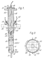
- the elements fundamentally related to the invention are a cable support tube 10 (which is a member capable of horizontal movement) and a plumb bob 11.
- the plumb bob 11 is supported on a tube 12 of smaller diameter than that of the plumb bob 11, and which consequently extends upwardly from the plumb bob 11.
- the tube 12 reaches into the lower regions of the support tube 10 and forms the energised electrode of a capacitative measuring system.
- a flexible electrically energised support cable 13 is attached to the tube 12.
- the tube 10 has a centralising band 14(a) which typically fits into. a structure which may be subjected to horizontal movement in the course of its use. It is this movement which requires to be measured and this movement is transmitted to the lower end of tube 10 which moves relative to the plumb.
- a second centralising band 14(b) in effect laterally locates the plumb-line suspension point (by way of the tube 10) at the chosen datum or reference level.
- the tube 10 as best seen in Figure 2, has 4-start helical grooves 20 and windows 21 disposed along parts of the grooves.
- Mineral insulated cables 22 are laid in the grooves 20 and where they pass across the windows 21 the cables have had their outer sheaths removed to expose bared conductors 23 which can be insulated with ceramic tubes.
- the windows 21 are arranged in four groups each of five windows; one group for each groove 20 and each five window group extending over approximately 110° of arc as shown by the lines 30 of Figure 3.
- the windows 21 are protected and screened on the outside by a thin sheet of stainless steel tack welded to the tube 10.
- the cables 22 each form a capacitor- electrode at the respective group of five windows 21 to operate in conjunction with the energised electrode formed by tube 12.
- the lines 30 form two pairs of orthogonally disposed electrodes to relate the movement of the tube 10 to the plumb bob 11.
- the equi-potential lines between the electrode pairs i.e. line of constant signal output from a differential amplifier fed from diagonal electrode pair
- dash lines 31 are also shown in Figure 3 by the dash lines 31.
- the plumb support cable 13 is carried in a tubular head 40 located in a double eccentric bush 41 so that the horizontal position of the tube 12 can be adjusted relative to the tube 10.
- a mineral insulated cable 42 passes through the bore of the head 40 to make electrical contact with the electrode (tube) 12 via the support cable 13.
- the energised support cable 13 is electrically connected to the mineral insulated cable 42 in the vicinity of the bush 41.
- An outer support tube 43 is shown passing through an access flange 44.
- the tube 43 is carried by a support flange 45 sealed to the access flange at a ring seal 46.
- the flange 45 has four glands 47 through which pass respective mineral insulated cables 22 to enter helical grooving in the tube 43 and the grooves 20 of the tube 10.
- the cable 42 passes up tube 40 and then helically along a shielding boss 48 and emerges through a gland 49 in a flange 50 sealed to the flange 51 of a shield tube 52 at a ring seal 53.
- One use for the. above described apparatus is to measure movements of an anti-vibation grid located immediately above the core of a liquid metal cooled fast reactor.
- the apparatus can record oscillatory movements as well as nominally permanent deflections.
- the plumb bob 11 is suspended from the reactor roof which forms a reliable datum. It is capable of operation in temperatures of up to nearly 600°C.
- the capacitative measuring techniques are known and in this respect reference may be had to an article by Walton in Transducer Technology, vol. no. 5 July/August 1979.
- the "X" and "Y” pairs of electrodes (lines 30 in Figure 3) are connected to respective "X” and “Y” differential charge amplifiers and thence to meters.
- the centre electrode (tube 12) is provided with an excitation alternating voltage and the relative movement of the electrode pairs with respect to the centre electrode 12 appears as "X" and "Y" coordinates on the meters.
Landscapes
- Physics & Mathematics (AREA)
- General Physics & Mathematics (AREA)
- Engineering & Computer Science (AREA)
- Radar, Positioning & Navigation (AREA)
- Remote Sensing (AREA)
- Power Engineering (AREA)
- Measurement Of Length, Angles, Or The Like Using Electric Or Magnetic Means (AREA)
- Monitoring And Testing Of Nuclear Reactors (AREA)
Description
- This invention relates to apparatus for the measurement of the movement of a member horizontally relative to a datum, which apparatus comprises means for capacitatively resolving said horizontal movement from a measurement of the inclination of a plumb member, said means comprising a plurality of electrodes located at different positions around the periphery of the plumb member and capacitively co-operating with the plumb member which functions as a further electrode. Such apparatus is known from US-A-4241995.
- The invention has one application to the problem of horizontal movement measurement in relatively inaccessible and hostile locations such as in the core of a liquid metal cooled nuclear reactor.
- The invention is characterised in that said peripherally-located electrodes are provided by conductors of mineral insulated cables from each of which the outer sheath has been stripped over a limited length to expose bare conductor portions. The cables may be located in helical grooving in a cable support tube (which is, in effect, the horizontally movable member), surrounding the plumb member, with windows cut in the tube through which the stripped lengths of cable co-operate with the plumb member.
- The plumb member preferably consists of a weighted flexible steel "energising" cable with the bob of the plumb member located below the mineral insulated cable support tube but with a narrow metal tube upwardly extending from the bob to the energising cable so as to reach into the support tube and be co-operable with the bare conductor portions through the windows of the support tube.
- One form of the invention will now be described with reference to the accompanying drawings in which:
- Figure 1 is a simplified sectional elevation of a position measuring apparatus;
- Figure 2 is a perspective view of a cable support tube in the apparatus of Figure 1; and
- Figure 3 is a plot of equi-potential lines in the cable support tube.
- In Figure 1 the elements fundamentally related to the invention are a cable support tube 10 (which is a member capable of horizontal movement) and a plumb bob 11. The plumb bob 11 is supported on a
tube 12 of smaller diameter than that of the plumb bob 11, and which consequently extends upwardly from the plumb bob 11. Thetube 12 reaches into the lower regions of thesupport tube 10 and forms the energised electrode of a capacitative measuring system. A flexible electricallyenergised support cable 13 is attached to thetube 12. By hanging the relatively wide plumb bob 11 below thetube 10 and providing thenarrow tube 12 as the capacitative electrode, larger movement can be measured. - The
tube 10 has a centralising band 14(a) which typically fits into. a structure which may be subjected to horizontal movement in the course of its use. It is this movement which requires to be measured and this movement is transmitted to the lower end oftube 10 which moves relative to the plumb. A second centralising band 14(b) in effect laterally locates the plumb-line suspension point (by way of the tube 10) at the chosen datum or reference level. - The
tube 10, as best seen in Figure 2, has 4-starthelical grooves 20 and windows 21 disposed along parts of the grooves. Mineral insulatedcables 22 are laid in thegrooves 20 and where they pass across the windows 21 the cables have had their outer sheaths removed to exposebared conductors 23 which can be insulated with ceramic tubes. The windows 21 are arranged in four groups each of five windows; one group for eachgroove 20 and each five window group extending over approximately 110° of arc as shown by thelines 30 of Figure 3. The windows 21 are protected and screened on the outside by a thin sheet of stainless steel tack welded to thetube 10. - Thus the
cables 22 each form a capacitor- electrode at the respective group of five windows 21 to operate in conjunction with the energised electrode formed bytube 12. As seen from Figure 3, thelines 30 form two pairs of orthogonally disposed electrodes to relate the movement of thetube 10 to the plumb bob 11. The equi-potential lines between the electrode pairs (i.e. line of constant signal output from a differential amplifier fed from diagonal electrode pair) are also shown in Figure 3 by the dash lines 31. - In order to present the fundamental elements described above into an operable unit a number of complementary elements are provided. These will now be described.
- The
plumb support cable 13 is carried in a tubular head 40 located in a doubleeccentric bush 41 so that the horizontal position of thetube 12 can be adjusted relative to thetube 10. A mineral insulatedcable 42 passes through the bore of the head 40 to make electrical contact with the electrode (tube) 12 via thesupport cable 13. Theenergised support cable 13 is electrically connected to the mineral insulatedcable 42 in the vicinity of thebush 41. Anouter support tube 43 is shown passing through an access flange 44. Thetube 43 is carried by asupport flange 45 sealed to the access flange at aring seal 46. Theflange 45 has fourglands 47 through which pass respective mineralinsulated cables 22 to enter helical grooving in thetube 43 and thegrooves 20 of thetube 10. Thecable 42 passes up tube 40 and then helically along ashielding boss 48 and emerges through agland 49 in aflange 50 sealed to theflange 51 of ashield tube 52 at aring seal 53. - One use for the. above described apparatus is to measure movements of an anti-vibation grid located immediately above the core of a liquid metal cooled fast reactor. The apparatus can record oscillatory movements as well as nominally permanent deflections. In this use, the plumb bob 11 is suspended from the reactor roof which forms a reliable datum. It is capable of operation in temperatures of up to nearly 600°C. The capacitative measuring techniques are known and in this respect reference may be had to an article by Walton in Transducer Technology, vol. no. 5 July/August 1979. Typically the "X" and "Y" pairs of electrodes (
lines 30 in Figure 3) are connected to respective "X" and "Y" differential charge amplifiers and thence to meters. The centre electrode (tube 12) is provided with an excitation alternating voltage and the relative movement of the electrode pairs with respect to thecentre electrode 12 appears as "X" and "Y" coordinates on the meters.
Claims (7)
Applications Claiming Priority (2)
| Application Number | Priority Date | Filing Date | Title |
|---|---|---|---|
| GB8118635 | 1981-06-17 | ||
| GB8118635 | 1981-06-17 |
Publications (3)
| Publication Number | Publication Date |
|---|---|
| EP0067675A2 EP0067675A2 (en) | 1982-12-22 |
| EP0067675A3 EP0067675A3 (en) | 1983-02-09 |
| EP0067675B1 true EP0067675B1 (en) | 1985-12-04 |
Family
ID=10522570
Family Applications (1)
| Application Number | Title | Priority Date | Filing Date |
|---|---|---|---|
| EP82303010A Expired EP0067675B1 (en) | 1981-06-17 | 1982-06-10 | Position measurement |
Country Status (4)
| Country | Link |
|---|---|
| US (1) | US4507603A (en) |
| EP (1) | EP0067675B1 (en) |
| JP (1) | JPS589006A (en) |
| DE (1) | DE3267770D1 (en) |
Families Citing this family (5)
| Publication number | Priority date | Publication date | Assignee | Title |
|---|---|---|---|---|
| US4949467A (en) * | 1988-10-03 | 1990-08-21 | Robert Oman | Inclinometer including an apparatus for maintaining a scientific and measuring instrument or the like in a level plane |
| US5406713A (en) * | 1988-10-03 | 1995-04-18 | Oman; Robert | Apparatus for maintaining a scientific and measuring instrument or the like in a level plane |
| US5414677A (en) * | 1994-02-09 | 1995-05-09 | Feagin, Jr.; Loyd C. | Ground movement sensor |
| FR2793317B1 (en) * | 1999-05-06 | 2001-07-13 | Daniel Roux | DEVICE FOR MEASURING THE POSITION VARIATION BETWEEN TWO POSITIONING REFERENCES LOCATED AT DIFFERENT ALTITUDES |
| US7432657B2 (en) * | 2005-06-30 | 2008-10-07 | General Electric Company | Ceramic lamp having shielded niobium end cap and systems and methods therewith |
Family Cites Families (14)
| Publication number | Priority date | Publication date | Assignee | Title |
|---|---|---|---|---|
| US2274735A (en) * | 1938-10-18 | 1942-03-03 | Melville F Peters | Apparatus for determining the position of the conductor in electrical cables |
| DE899561C (en) * | 1943-09-04 | 1953-12-14 | Aeg | Device for precise setting and ongoing monitoring of the spatial position, especially the vertical, by means of a pendulum |
| US2633028A (en) * | 1949-10-31 | 1953-03-31 | Bendix Aviat Corp | Pick-off device |
| US2604512A (en) * | 1950-12-06 | 1952-07-22 | Gen Electric | Concentric tester |
| US2892152A (en) * | 1953-09-22 | 1959-06-23 | Buisson Pierre | System for measuring small displacements of a body along three coordinate axes |
| FR1111036A (en) * | 1953-11-07 | 1956-02-21 | Siemens Ag | Device for adjusting the size of the loop formed by a continuously moving wire or strip product |
| US2825978A (en) * | 1955-08-01 | 1958-03-11 | Hoffman Electronics Corp | Electromechanical sensing device |
| DE1490389A1 (en) * | 1963-03-26 | 1969-05-22 | Siemens Ag | Arrangement for checking the concentric position of conductors in insulating materials |
| US3323699A (en) * | 1965-10-04 | 1967-06-06 | Allegheny Ludlum Steel | Strip centerline sensor and control |
| US3555691A (en) * | 1967-01-28 | 1971-01-19 | Continental Elektro Ind Ag | Clinometric pendulum apparatus |
| GB1410051A (en) * | 1972-01-12 | 1975-10-15 | Russell M K | Remote angle measurement |
| US3997976A (en) * | 1973-09-14 | 1976-12-21 | Massachusetts Institute Of Technology | Sensitive tiltmeter |
| JPS6010245B2 (en) * | 1976-05-13 | 1985-03-15 | 株式会社明石製作所 | Tilt and vibration meter for rock measurement |
| JPS5491355A (en) * | 1977-12-28 | 1979-07-19 | Nippon Chemical Ind | Device for measuring displacement |
-
1982
- 1982-06-10 EP EP82303010A patent/EP0067675B1/en not_active Expired
- 1982-06-10 DE DE8282303010T patent/DE3267770D1/en not_active Expired
- 1982-06-11 US US06/387,560 patent/US4507603A/en not_active Expired - Fee Related
- 1982-06-17 JP JP57104645A patent/JPS589006A/en active Pending
Also Published As
| Publication number | Publication date |
|---|---|
| EP0067675A3 (en) | 1983-02-09 |
| EP0067675A2 (en) | 1982-12-22 |
| US4507603A (en) | 1985-03-26 |
| JPS589006A (en) | 1983-01-19 |
| DE3267770D1 (en) | 1986-01-16 |
Similar Documents
| Publication | Publication Date | Title |
|---|---|---|
| US2563062A (en) | Electrostatic shield for ph electrodes | |
| US5162740A (en) | Electrode array construction featuring current emitting electrodes and resistive sheet guard electrode for investigating formations along a borehole | |
| US3928796A (en) | Capacitive displacement transducer | |
| US4121154A (en) | Alternating current potential measuring device | |
| EP0503032A1 (en) | Capacitance sensing probe. | |
| JPH0348472B2 (en) | ||
| NO303418B1 (en) | Fire logging method and apparatus | |
| JPS631524B2 (en) | ||
| SE507933C2 (en) | Method, apparatus and sensor for capacitively detecting fields and voltages and their use | |
| EP0552088B1 (en) | Well logging method and apparatus using passive azimuthal electrodes | |
| US4507603A (en) | Apparatus for the measurement of the movement of a member horizontally relative to a datum | |
| US6498499B1 (en) | Device for measuring the capacitance of electrical wires | |
| US2633485A (en) | Electrical dip meter for logging boreholes | |
| EP3772653A1 (en) | Voltage sensing structure | |
| CA1139369A (en) | Method and apparatus for measuring the resistivity of fluids in a borehole | |
| JPH06347436A (en) | Device and method for measuring filling state in electrostatic capacity mode | |
| US2721976A (en) | Capacitance measuring electrode | |
| JPS59182316A (en) | Measuring device for velocity of flow | |
| US6246244B1 (en) | Method and device for measuring axial deviation in a taut wire alignment system | |
| JP2655886B2 (en) | Laser processing machine nozzle distance detection device | |
| US6490808B1 (en) | Topographic measuring device | |
| JP2737056B2 (en) | Shielding method for physical quantity measurement system of movable high voltage body | |
| SU1409960A1 (en) | Resistivity logging sonde | |
| RU1784714C (en) | Electromechanical ground-sounding device | |
| JPS644628B2 (en) |
Legal Events
| Date | Code | Title | Description |
|---|---|---|---|
| PUAI | Public reference made under article 153(3) epc to a published international application that has entered the european phase |
Free format text: ORIGINAL CODE: 0009012 |
|
| PUAL | Search report despatched |
Free format text: ORIGINAL CODE: 0009013 |
|
| AK | Designated contracting states |
Designated state(s): DE FR GB IT |
|
| AK | Designated contracting states |
Designated state(s): DE FR GB IT |
|
| 17P | Request for examination filed |
Effective date: 19830704 |
|
| ITF | It: translation for a ep patent filed | ||
| GRAA | (expected) grant |
Free format text: ORIGINAL CODE: 0009210 |
|
| AK | Designated contracting states |
Designated state(s): DE FR GB IT |
|
| REF | Corresponds to: |
Ref document number: 3267770 Country of ref document: DE Date of ref document: 19860116 |
|
| ET | Fr: translation filed | ||
| PLBE | No opposition filed within time limit |
Free format text: ORIGINAL CODE: 0009261 |
|
| STAA | Information on the status of an ep patent application or granted ep patent |
Free format text: STATUS: NO OPPOSITION FILED WITHIN TIME LIMIT |
|
| 26N | No opposition filed | ||
| REG | Reference to a national code |
Ref country code: FR Ref legal event code: ST |
|
| PGFP | Annual fee paid to national office [announced via postgrant information from national office to epo] |
Ref country code: GB Payment date: 19900601 Year of fee payment: 9 |
|
| PGFP | Annual fee paid to national office [announced via postgrant information from national office to epo] |
Ref country code: DE Payment date: 19900608 Year of fee payment: 9 |
|
| PGFP | Annual fee paid to national office [announced via postgrant information from national office to epo] |
Ref country code: FR Payment date: 19900614 Year of fee payment: 9 |
|
| REG | Reference to a national code |
Ref country code: FR Ref legal event code: AR |
|
| REG | Reference to a national code |
Ref country code: FR Ref legal event code: BR |
|
| PG25 | Lapsed in a contracting state [announced via postgrant information from national office to epo] |
Ref country code: GB Effective date: 19910610 |
|
| ITTA | It: last paid annual fee | ||
| GBPC | Gb: european patent ceased through non-payment of renewal fee | ||
| PG25 | Lapsed in a contracting state [announced via postgrant information from national office to epo] |
Ref country code: FR Effective date: 19920228 |
|
| PG25 | Lapsed in a contracting state [announced via postgrant information from national office to epo] |
Ref country code: DE Effective date: 19920401 |
|
| REG | Reference to a national code |
Ref country code: FR Ref legal event code: ST |