EP0067501A1 - Alloy suitable for use in a radioactive radiation environment and a reactor core component formed therefrom - Google Patents
Alloy suitable for use in a radioactive radiation environment and a reactor core component formed therefrom Download PDFInfo
- Publication number
- EP0067501A1 EP0067501A1 EP82301404A EP82301404A EP0067501A1 EP 0067501 A1 EP0067501 A1 EP 0067501A1 EP 82301404 A EP82301404 A EP 82301404A EP 82301404 A EP82301404 A EP 82301404A EP 0067501 A1 EP0067501 A1 EP 0067501A1
- Authority
- EP
- European Patent Office
- Prior art keywords
- nitrogen
- radiation
- alloy
- austenite
- reactor core
- Prior art date
- Legal status (The legal status is an assumption and is not a legal conclusion. Google has not performed a legal analysis and makes no representation as to the accuracy of the status listed.)
- Granted
Links
Images


Classifications
-
- C—CHEMISTRY; METALLURGY
- C22—METALLURGY; FERROUS OR NON-FERROUS ALLOYS; TREATMENT OF ALLOYS OR NON-FERROUS METALS
- C22C—ALLOYS
- C22C38/00—Ferrous alloys, e.g. steel alloys
- C22C38/001—Ferrous alloys, e.g. steel alloys containing N
-
- C—CHEMISTRY; METALLURGY
- C22—METALLURGY; FERROUS OR NON-FERROUS ALLOYS; TREATMENT OF ALLOYS OR NON-FERROUS METALS
- C22C—ALLOYS
- C22C38/00—Ferrous alloys, e.g. steel alloys
- C22C38/18—Ferrous alloys, e.g. steel alloys containing chromium
- C22C38/40—Ferrous alloys, e.g. steel alloys containing chromium with nickel
-
- Y—GENERAL TAGGING OF NEW TECHNOLOGICAL DEVELOPMENTS; GENERAL TAGGING OF CROSS-SECTIONAL TECHNOLOGIES SPANNING OVER SEVERAL SECTIONS OF THE IPC; TECHNICAL SUBJECTS COVERED BY FORMER USPC CROSS-REFERENCE ART COLLECTIONS [XRACs] AND DIGESTS
- Y10—TECHNICAL SUBJECTS COVERED BY FORMER USPC
- Y10S—TECHNICAL SUBJECTS COVERED BY FORMER USPC CROSS-REFERENCE ART COLLECTIONS [XRACs] AND DIGESTS
- Y10S376/00—Induced nuclear reactions: processes, systems, and elements
- Y10S376/90—Particular material or material shapes for fission reactors
Definitions
- This invention relates to an alloy suitable for use in an environment exposed to radioactive radiation, especially neutron radiation, and more specifically to an austenite steel for use in a nuclear reactor and to reactor core components formed at least partly from the steel.
- Reactor core members such as core supportors, the core shroud, control rods etc. disposed inside a nuclear reactor are exposed to neutron radiation during use. This causes damage to the materials, which can markedly change their characteristics. Deterioration of the material characteristics is critical to the safety and reliability of the reactor. Therefore, the reactor core member material must be selected with this difficulty in mind.
- the neutron radiation of such high energy as to be incomparable with that in fission reactors would take place.
- the first wall material encompassing the plasma is exposed to severe radiation damage. Damage due to gas atoms (hydrogen and helium atoms) generated by the nuclear conversion process is an extremely critical problem, in addition to the above-mentioned swelling phenomenon.
- An object of the invention is to provide an alloy suitable for use in an environment exposed to radioactive radiation and having high radiation resistance.
- the present invention proposes that the alloy, suitable for use in an environment exposed to radioactive radiation, contains nitrogen in an amount exceeding the impurity level.
- environment exposed to radioactive radiation denotes typically an environment that is exposed to neutron radiation of at least 10 16 nvt, e.g. at least 10 20 nvt.
- the environment in a reactor core is the major example.
- the method of achieving the desired nitrogen content is preferably to use a base alloy which contains large quantities of nitrogen or to add an alloy which contains a large amount of nitrogen to the base alloy.
- the amount of nitrogen incorporated preferably exceeds the impurity level and especially is such an amount that the formation of a nitride in the alloy is substantially not permitted.
- nitrogen exists in the alloy substantially in solid solution.
- the alloy preferably primarily consists of Cr-Ni austenite steel containing nitrogen in an amount exceeding the impurity level and having an austenite structure.
- the amount of nitrogen is preferably from 0.05 to 0.2 wt%.
- this steel comprises principally Fe, contains not more than 0.03 wt% C, not more than 1 wt% Si, not more than 2 wt% Mn, 15 to 25 wt% Cr, 8 to 35 wt% Ni and 0.05 to 0.2 wt% N and has primarily an austenite structure.
- an austenite steel having a full austenite structure is especially preferred.
- the inventors of the present invention have examined in detail the effects of nitrogen on the radiation damage, using an ultra- high voltage electron microscope, and have found that, on the contrary, the nitrogen atoms tend to reduce the damage due to the atoms introduced into the lattice by the radiation and to the interaction between crystal defects such as the void points and the nitrogen atoms.
- austenite steel exhibits higher radiation resistance.
- stainless steel when irradiated with neutrons in doses of at least 10 23 n/m 2 (0.1 MeV), stainless steel (SUS 304) stretches less than when it is not irradiated with neutrons.
- SUS 304 stretches less than when it is not irradiated with neutrons.
- the inventors have discovered that stainless steels are made brittle by neutron radiation chiefly due to dislocation loops formed in the steel by the radiation, and they have thus attempted to control the dislocation loops that are formed by the neutron radiation by using an austenite stainless steel containing not more than 0.03% carbon and 0,05 to 0.15 wt% nitrogen.
- the carbon content is preferably low so as to prevent precipitation of carbide.
- the carbon content is preferably also such that it does not permit precipitation of carbide.
- the carbon content is therefore preferably not more than 0.03%, more preferably not more than 0.01%and especially preferably from 0.003 to 0.01%.
- the N content is preferably at least 0.025%. If the N content is increased, the beneficial effect is also increased but a large N content tends to permit formation of a nitride. Precipitation of the nitride reduces the solid solution N content in the matrix and forms a Cr nitride, thus having an adverse effect upon SCC resistance. For these reasons, it is preferred that the N content is not more than 0.2% and more preferably is from 0.05 to 0.15%. To make up for the decrease in strength due to the decrease in the C content by the addition of N, the total amount of C and N is preferably at least 0.09%.
- impurity elements such as P, S and the like may also be present.
- Austenite stainless steel containing 1 to 3% Mo is especially suitable. Besides C and N contents as described above, the preferred ranges for this steel are Cr: 15 - 20%, Ni: 10 - 15%, Mo: 2 - 3%.
- the material of the present invention may be used in the form having a full austenite structure after solid solution treatment, but it may also be used after cold working subsequent to the solid solution treatment.
- the alloy of the invention preferably comprises at least a Ni base alloy containing nitrogen in an amount exceeding the impurity level and Cr in such an amount as not to permit the formation of a substantial ⁇ phase.
- the nitrogen content is from 0.05 to 0.15% and the Cr content from 15 to 25%.
- the Ni base alloy may contain considerable amounts of elements such as Mo, W, Al, Ti, Nb, Zr and the like.
- the alloy of the invention consists of low alloy steel containing nitrogen in an amount exceeding the impurity level and having primarily ferrite+pearlite structure or primarily bainite structure.
- the nitrogen content is from 0.05 to 0.15%.
- the low alloy steel may contain considerable amounts of Cr, Mo, W, V, Cu, Ni and the like.
- the austenite stainless steel serves as a material for forming reactor core components including machine parts, that receive neutron irradiation in reactor cores. All of the core components subject to neutron radiation need not be made of the austenite stainless steel. Only those core members disposed in regions which receive particularly intense neutron irradiation should be made of the austenite stainless steel.
- SUS 304 stretches less when it is irradiated with neutrons in doses of at least 10 23 n/ m 2 (0.1 MeV), compared with when it is not irradiated with neutrons. Therefore, core members disposed in the places irradiated with neutrons in doses of at least 10 23 n/m 2 ( 0 .1 M e V ), such as control rods, neutron counter tubes, core supporters, core shrouds, neutron source pipes etc. should be made of the austenite stainless steel of the invention.
- Sample 1 is a comparative material and sample 2 is a material of the present invention.
- the carbon content is substantially the same in the two samples, but their nitrogen contents are remarkably different.
- the two steels have an austenite structure.
- Specimens having the same contents as above were subjected to solution treatment at 1050°C for 15 minutes, and then irradiated with electrons in an ultrahigh-voltage electron microscope (acceleration voltage 1MV).
- Figs. 3(A) and 3(B) show the formation of dislocation loops when these specimens 2 and 1 respectively, are irradiated at a rate of 4.8 x 10 23 e/sec (2.2 x 10 -3 dpa/sec) which corresponds to a neutron radiation of1 x 1027 n/m 2 at a temperature of 500°C.
- Specimen 2 (Fig. 3(A)) which contains a large amount of nitrogen only permits the dislocation loops to grow very little compared with specimen 1 (Fig. 3(B)). This indicates that specimen 2 is embrittled very little.
- Figs. 4 and 5 show that in specimen 2, the growth of dislocation loops is restrained even when it is irradiated at these temperatures.
- the core members made of the austenite-type stainless steel can be prevented from being embrittled by neutron irradiation.
- the material of the present invention can be expected to show excellent radiation resistance to neutron radiation from comparison with the degree of damage of conventional materials.
- Fig. 6 shows the core of a BWR-type reactor, having neutron source pipes 1, a core support member 2, neutron counter tubes 3, control rods 4 and a core shroud 5.
- These core members are subjected to intense neutron radiation, and hence are, according to the invention, made of austenite stainless steel which contains not more than 0.03% by weight of carbon and 0.05 to 0.15% by weight of nitrogen. It is, of course, allowable to make other fine parts using this austenite stainless steel, in addition to the core members 1 to 5.
- materials of the invention can be used for, for example, the core shroud, core supporters, control rods etc. of a PWR-type reactor core, and the fuel pins, wrapper tubes etc. of a FBR-type reactor core.
- the prevention or reduction of embrittlement by neutron radiation can increase the reliability of the reactor core, and can lengthen the life of the core components and internal instruments and appliances.
Abstract
Description
- This invention relates to an alloy suitable for use in an environment exposed to radioactive radiation, especially neutron radiation, and more specifically to an austenite steel for use in a nuclear reactor and to reactor core components formed at least partly from the steel.
- . Reactor core members, such as core supportors, the core shroud, control rods etc. disposed inside a nuclear reactor are exposed to neutron radiation during use. This causes damage to the materials, which can markedly change their characteristics. Deterioration of the material characteristics is critical to the safety and reliability of the reactor. Therefore, the reactor core member material must be selected with this difficulty in mind.
- In light-water reactors, it is feared that the material of internal instruments and appliances may suffer radiation-embrittlement during operation due to the neutron radiation. Besides the embrittlement due to the neutron radiation, the SCC phenomenon in water at high temperature and high pressure must also be taken into account in selecting the material for the core.
- In a fast breeder reactor, damage to a fuel covering tube, a core tube or the like has specifically been a critical problem. In such a reactor, the temperature of the coolant (liquid sodium) is relatively high, e.g. 350 to 500°C, and the amount of high speed neutron radiation is far greater than in a light-water reactor. Consequently, voids can occur in the material exposed to the neutron radiation, causing a serious problem of swelling (of volume).
- In fusion reactors, the neutron radiation of such high energy as to be incomparable with that in fission reactors would take place. Hence, the first wall material encompassing the plasma is exposed to severe radiation damage. Damage due to gas atoms (hydrogen and helium atoms) generated by the nuclear conversion process is an extremely critical problem, in addition to the above-mentioned swelling phenomenon.
- There are various proposals to prevent swelling of the core material exposed to neutron radiation. For example, in Japanese Laid-open Patent Application 54-36498, an austenite stainless steel including titanium, niobium and carbon is disclosed, and in Japanese Laid-open Patent Application 54-84197, there is disclosed a method of treatment of austenite stainless steel in which the steel is subjected to solid solution treatment at a temperature from 950 to 1200°C after being finally formed, and thereafter undergoes an aging treatment at a temperature of about 600 to 800°C for about 50 hours.
- An object of the invention is to provide an alloy suitable for use in an environment exposed to radioactive radiation and having high radiation resistance.
- Essentially, the present invention proposes that the alloy, suitable for use in an environment exposed to radioactive radiation, contains nitrogen in an amount exceeding the impurity level.
- The term "environment exposed to radioactive radiation" used herein denotes typically an environment that is exposed to neutron radiation of at least 10 16 nvt, e.g. at least 1020 nvt. The environment in a reactor core is the major example.
- The method of achieving the desired nitrogen content is preferably to use a base alloy which contains large quantities of nitrogen or to add an alloy which contains a large amount of nitrogen to the base alloy. The amount of nitrogen incorporated preferably exceeds the impurity level and especially is such an amount that the formation of a nitride in the alloy is substantially not permitted. Preferably nitrogen exists in the alloy substantially in solid solution.
- The alloy preferably primarily consists of Cr-Ni austenite steel containing nitrogen in an amount exceeding the impurity level and having an austenite structure. In this case, the amount of nitrogen is preferably from 0.05 to 0.2 wt%. Preferably this steel comprises principally Fe, contains not more than 0.03 wt% C, not more than 1 wt% Si, not more than 2 wt% Mn, 15 to 25 wt% Cr, 8 to 35 wt% Ni and 0.05 to 0.2 wt% N and has primarily an austenite structure. Especially preferred is an austenite steel having a full austenite structure.
- The conventional thinking hitherto has been that nitrogen present in austenite steel would result in helium damage at a high temperature due to helium atoms generated by the nuclear reaction resulting from neutron radiation. Hence, steps have been taken to reduce the nitrogen content.
- However, the inventors of the present invention have examined in detail the effects of nitrogen on the radiation damage, using an ultra- high voltage electron microscope, and have found that, on the contrary, the nitrogen atoms tend to reduce the damage due to the atoms introduced into the lattice by the radiation and to the interaction between crystal defects such as the void points and the nitrogen atoms.
- In other words, the inventors have discovered that when nitrogen is added, austenite steel exhibits higher radiation resistance.
- For example, when irradiated with neutrons in doses of at least 1023 n/m2 (0.1 MeV), stainless steel (SUS 304) stretches less than when it is not irradiated with neutrons. Through research in developing materials that have resistance against neutron radiation and that may be substituted for SUS 304, the inventors have discovered that stainless steels are made brittle by neutron radiation chiefly due to dislocation loops formed in the steel by the radiation, and they have thus attempted to control the dislocation loops that are formed by the neutron radiation by using an austenite stainless steel containing not more than 0.03% carbon and 0,05 to 0.15 wt% nitrogen.
- The chemical components of the austenite steel of the present invention will next be described.
- For good radiation resistance, precipitation pf C as carbide is not preferred . Hence, the carbon content is preferably low so as to prevent precipitation of carbide, For increased SCC resistance (in the environment of pure water at high temperature and high pressure in a light-water reactor), the carbon content is preferably also such that it does not permit precipitation of carbide. The carbon content is therefore preferably not more than 0.03%, more preferably not more than 0.01%and especially preferably from 0.003 to 0.01%.
- To reduce radiation damage, the N content is preferably at least 0.025%. If the N content is increased, the beneficial effect is also increased but a large N content tends to permit formation of a nitride. Precipitation of the nitride reduces the solid solution N content in the matrix and forms a Cr nitride, thus having an adverse effect upon SCC resistance. For these reasons, it is preferred that the N content is not more than 0.2% and more preferably is from 0.05 to 0.15%. To make up for the decrease in strength due to the decrease in the C content by the addition of N, the total amount of C and N is preferably at least 0.09%.
- In addition to C and N, impurity elements such as P, S and the like may also be present.
- Austenite stainless steel containing 1 to 3% Mo is especially suitable. Besides C and N contents as described above, the preferred ranges for this steel are Cr: 15 - 20%, Ni: 10 - 15%, Mo: 2 - 3%.
- The material of the present invention may be used in the form having a full austenite structure after solid solution treatment, but it may also be used after cold working subsequent to the solid solution treatment.
- The alloy of the invention preferably comprises at least a Ni base alloy containing nitrogen in an amount exceeding the impurity level and Cr in such an amount as not to permit the formation of a substantial α phase. Preferably, the nitrogen content is from 0.05 to 0.15% and the Cr content from 15 to 25%. The Ni base alloy may contain considerable amounts of elements such as Mo, W, Al, Ti, Nb, Zr and the like.
- In another form, the alloy of the invention consists of low alloy steel containing nitrogen in an amount exceeding the impurity level and having primarily ferrite+pearlite structure or primarily bainite structure. Preferably, the nitrogen content is from 0.05 to 0.15%. The low alloy steel may contain considerable amounts of Cr, Mo, W, V, Cu, Ni and the like.
- In an aspect of the present invention, the austenite stainless steel serves as a material for forming reactor core components including machine parts, that receive neutron irradiation in reactor cores. All of the core components subject to neutron radiation need not be made of the austenite stainless steel. Only those core members disposed in regions which receive particularly intense neutron irradiation should be made of the austenite stainless steel.
- For example, as already mentioned SUS 304 stretches less when it is irradiated with neutrons in doses of at least 10 23 n/m2 (0.1 MeV), compared with when it is not irradiated with neutrons. Therefore, core members disposed in the places irradiated with neutrons in doses of at least 10 23 n/m 2 (0.1 MeV), such as control rods, neutron counter tubes, core supporters, core shrouds, neutron source pipes etc. should be made of the austenite stainless steel of the invention.
- An embodiment of the invention will now be described by way of example with reference to the accompanying drawings, in which:-
- Fig. 1 is a graph of the relation between amount of swelling and radiation temperature;
- Fig. 2 is a graph of the relation between void density and radiation temperature;
- Figs. 3(A) and 3(B) are electron microphotographs of sectioned specimens illustrating the formation of dislocation loops by neutron radiation;
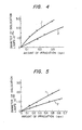
- Figs. 4 and 5 are graphs of the relations between growth of dislocation loops and neutron radiation dose when specimens are irradiated at temperatures of 550°C and 470°C respectively; and
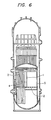
- Fig. 6 is a sectional view schematically showing the construction of a reactor core having components embodying the present invention.
- The chemical compositions of the samples used are given in the following table. Sample 1 is a comparative material and
sample 2 is a material of the present invention. The carbon content is substantially the same in the two samples, but their nitrogen contents are remarkably different. The two steels have an austenite structure. - Each sample was subjected to solid solution treatment by heating at 1050 - 1100°C for 30 minutes, and then electrolytically polished. Electron radiation was effected with a ultra-high voltage electron microscope. Neutron radiation damage corresponding to approximately 5 x 10 23 n/cm2 was applied at a work voltage of 1,000 keV to permit observation of the structure rearrangement in the sample and the formation of voids. The results are shown in Figures 1 and 2, where the
reference numbers 1 and 2 indicate the curves for the two samples. - As Figure 1 shows,
sample 2 having a higher N content exhibits less swelling than sample 1. 'The same improvement appears clearly in the difference of void density shown in Figure 2. As will be appreciated, the presence of nitrogen serves to restrict swelling due to the void formation, and the addition of nitrogen is therefore extremely effective for improving radiation resistance.
- Specimens having the same contents as above were subjected to solution treatment at 1050°C for 15 minutes, and then irradiated with electrons in an ultrahigh-voltage electron microscope (acceleration voltage 1MV). Figs. 3(A) and 3(B) show the formation of dislocation loops when these
specimens 2 and 1 respectively, are irradiated at a rate of 4.8 x 10 23 e/sec (2.2 x 10⁻³ dpa/sec) which corresponds to a neutron radiation of1 x 1027 n/m2 at a temperature of 500°C. Specimen 2 (Fig. 3(A)) which contains a large amount of nitrogen only permits the dislocation loops to grow very little compared with specimen 1 (Fig. 3(B)). This indicates thatspecimen 2 is embrittled very little. - Figs. 4 and 5 (irradiation at 550°C and 470°C respectively) show that in
specimen 2, the growth of dislocation loops is restrained even when it is irradiated at these temperatures. By adding nitrogen to the austenite stainless steel, therefore, the core members made of the austenite-type stainless steel can be prevented from being embrittled by neutron irradiation. - Though the characteristics of material damage due to electron radiation are different from those of damage due to neutron radiation, the material of the present invention can be expected to show excellent radiation resistance to neutron radiation from comparison with the degree of damage of conventional materials.
- Fig. 6 shows the core of a BWR-type reactor, having neutron source pipes 1, a
core support member 2,neutron counter tubes 3,control rods 4 and acore shroud 5. These core members are subjected to intense neutron radiation, and hence are, according to the invention, made of austenite stainless steel which contains not more than 0.03% by weight of carbon and 0.05 to 0.15% by weight of nitrogen. It is, of course, allowable to make other fine parts using this austenite stainless steel, in addition to the core members 1 to 5. - Furthermore, materials of the invention can be used for, for example, the core shroud, core supporters, control rods etc. of a PWR-type reactor core, and the fuel pins, wrapper tubes etc. of a FBR-type reactor core.
- The prevention or reduction of embrittlement by neutron radiation can increase the reliability of the reactor core, and can lengthen the life of the core components and internal instruments and appliances.
Claims (10)
the alloy contains nitrogen in an amount exceeding the impurity level.
Applications Claiming Priority (4)
| Application Number | Priority Date | Filing Date | Title |
|---|---|---|---|
| JP56040666A JPS6046177B2 (en) | 1981-03-20 | 1981-03-20 | Components of reactor internal equipment |
| JP40666/81 | 1981-03-20 | ||
| JP141034/81 | 1981-09-09 | ||
| JP56141034A JPS5845358A (en) | 1981-09-09 | 1981-09-09 | Core of nuclear reactor |
Publications (3)
| Publication Number | Publication Date |
|---|---|
| EP0067501A1 true EP0067501A1 (en) | 1982-12-22 |
| EP0067501B1 EP0067501B1 (en) | 1986-08-06 |
| EP0067501B2 EP0067501B2 (en) | 1993-10-20 |
Family
ID=26380155
Family Applications (1)
| Application Number | Title | Priority Date | Filing Date |
|---|---|---|---|
| EP82301404A Expired - Lifetime EP0067501B2 (en) | 1981-03-20 | 1982-03-18 | Alloy suitable for use in a radioactive radiation environment and a reactor core component formed therefrom |
Country Status (4)
| Country | Link |
|---|---|
| US (1) | US4560407A (en) |
| EP (1) | EP0067501B2 (en) |
| CA (1) | CA1194711A (en) |
| DE (1) | DE3272417D1 (en) |
Cited By (2)
| Publication number | Priority date | Publication date | Assignee | Title |
|---|---|---|---|---|
| EP0447109A1 (en) * | 1990-03-14 | 1991-09-18 | Hitachi, Ltd. | Austenitic steel having superior characteristics in resistance against stress corrosion cracking, method for producing of same and usage of same |
| EP0530725A1 (en) * | 1991-09-03 | 1993-03-10 | Hitachi, Ltd. | Austenitic stainless steel having superior resistance to irradiation-induced segregation |
Families Citing this family (2)
| Publication number | Priority date | Publication date | Assignee | Title |
|---|---|---|---|---|
| US4927468A (en) * | 1988-11-30 | 1990-05-22 | The United States Of America As Represented By The United States Department Of Energy | Process for making a martensitic steel alloy fuel cladding product |
| JP2004124173A (en) * | 2002-10-02 | 2004-04-22 | Nippon Chuzo Kk | Nonmagnetic austenitic stainless steel and manufacturing method therefor |
Citations (4)
| Publication number | Priority date | Publication date | Assignee | Title |
|---|---|---|---|---|
| DE1533158B1 (en) * | 1965-06-22 | 1970-01-02 | Avesta Jernverks Ab | Use of a rollable and weldable stainless steel for the production of objects which are intended for use under neutron radiation and at temperatures between -200 and +400 ° C, and as welding filler material |
| US3854937A (en) * | 1970-12-14 | 1974-12-17 | Nippon Steel Corp | Pitting corrosion resistant austenite stainless steel |
| FR2252415A1 (en) * | 1973-11-26 | 1975-06-20 | Atomic Energy Commission | |
| US4246047A (en) * | 1977-12-27 | 1981-01-20 | Sumitomo Electric Industries, Ltd. | Non-magnetic stainless steel |
Family Cites Families (2)
| Publication number | Priority date | Publication date | Assignee | Title |
|---|---|---|---|---|
| US2602737A (en) * | 1949-05-10 | 1952-07-08 | Union Carbide & Carbon Corp | Corrosion resisting steels |
| US3563728A (en) * | 1968-03-12 | 1971-02-16 | Westinghouse Electric Corp | Austenitic stainless steels for use in nuclear reactors |
-
1982
- 1982-03-15 US US06/358,211 patent/US4560407A/en not_active Expired - Lifetime
- 1982-03-18 DE DE8282301404T patent/DE3272417D1/en not_active Expired
- 1982-03-18 EP EP82301404A patent/EP0067501B2/en not_active Expired - Lifetime
- 1982-03-19 CA CA000398877A patent/CA1194711A/en not_active Expired
Patent Citations (4)
| Publication number | Priority date | Publication date | Assignee | Title |
|---|---|---|---|---|
| DE1533158B1 (en) * | 1965-06-22 | 1970-01-02 | Avesta Jernverks Ab | Use of a rollable and weldable stainless steel for the production of objects which are intended for use under neutron radiation and at temperatures between -200 and +400 ° C, and as welding filler material |
| US3854937A (en) * | 1970-12-14 | 1974-12-17 | Nippon Steel Corp | Pitting corrosion resistant austenite stainless steel |
| FR2252415A1 (en) * | 1973-11-26 | 1975-06-20 | Atomic Energy Commission | |
| US4246047A (en) * | 1977-12-27 | 1981-01-20 | Sumitomo Electric Industries, Ltd. | Non-magnetic stainless steel |
Non-Patent Citations (2)
| Title |
|---|
| WERKSTOFFE UND KORROSION, vol.22, no.9, September 1971 * |
| WERKSTOFFE UND KORROSION, vol.23, no.11, November 1972 * |
Cited By (3)
| Publication number | Priority date | Publication date | Assignee | Title |
|---|---|---|---|---|
| EP0447109A1 (en) * | 1990-03-14 | 1991-09-18 | Hitachi, Ltd. | Austenitic steel having superior characteristics in resistance against stress corrosion cracking, method for producing of same and usage of same |
| EP0530725A1 (en) * | 1991-09-03 | 1993-03-10 | Hitachi, Ltd. | Austenitic stainless steel having superior resistance to irradiation-induced segregation |
| US5316597A (en) * | 1991-09-03 | 1994-05-31 | Hitachi, Ltd. | A nuclear reactor comprising a reactor vessel and structural members made of an austenitic stainless steel having superior resistance to irradiation-induced segregation |
Also Published As
| Publication number | Publication date |
|---|---|
| DE3272417D1 (en) | 1986-09-11 |
| EP0067501B1 (en) | 1986-08-06 |
| EP0067501B2 (en) | 1993-10-20 |
| CA1194711A (en) | 1985-10-08 |
| US4560407A (en) | 1985-12-24 |
Similar Documents
| Publication | Publication Date | Title |
|---|---|---|
| Bates et al. | Irradiation-induced swelling in commercial alloys | |
| Diercks et al. | Alloying and impurity effects in vanadium-base alloys | |
| US4011133A (en) | Austenitic stainless steel alloys having improved resistance to fast neutron-induced swelling | |
| KR0147082B1 (en) | Austenitic cr-ni-mn-steel excellent in resistance to neutron irradiation embrittlement | |
| US4818485A (en) | Radiation resistant austenitic stainless steel alloys | |
| EP0106426B1 (en) | Austenitic alloys and reactor components made thereof | |
| US5316597A (en) | A nuclear reactor comprising a reactor vessel and structural members made of an austenitic stainless steel having superior resistance to irradiation-induced segregation | |
| US5278881A (en) | Fe-Cr-Mn Alloy | |
| EP0076110B1 (en) | Maraging superalloys and heat treatment processes | |
| Lee et al. | A mechanism of swelling suppression in phosphorous-modified Fe-Ni-Cr alloys | |
| Powell et al. | Swelling of several commercial alloys following high fluence neutron irradiation | |
| EP0067501A1 (en) | Alloy suitable for use in a radioactive radiation environment and a reactor core component formed therefrom | |
| US3496034A (en) | Steel resistant to embrittlement by neutron radiation | |
| US3856517A (en) | Irradiation swelling resistant alloy for use in fast neutron reactors | |
| Bryk et al. | Microstructure investigation of Cr and Cr alloys irradiated with heavy ions | |
| JPH05171359A (en) | Austenitic stainless steel markedly lowered in contents of nitrogen and boron | |
| RU2124065C1 (en) | Austenite, iron-chromium-nickel alloy for spring members of atomic reactors | |
| Jung | Relevance of the displacement damage concept for the evaluation of radiation effects in metals | |
| JPH07100842B2 (en) | Reactor core member with excellent stress corrosion cracking resistance | |
| JPS6017058A (en) | Alloy for apparatus in high irradiation region | |
| JPS6046177B2 (en) | Components of reactor internal equipment | |
| Kimoto et al. | Dose dependence of void swelling and precipitation behavior in MC carbide dispersed austenitic Fe-Ni-Cr alloys | |
| Shibahara et al. | Effects of metallurgical variables on swelling of modified 316 and higher Ni austenitic stainless steels | |
| JPS6166188A (en) | Control rod for nuclear reactor | |
| JPS5845358A (en) | Core of nuclear reactor |
Legal Events
| Date | Code | Title | Description |
|---|---|---|---|
| PUAI | Public reference made under article 153(3) epc to a published international application that has entered the european phase |
Free format text: ORIGINAL CODE: 0009012 |
|
| 17P | Request for examination filed |
Effective date: 19820503 |
|
| AK | Designated contracting states |
Designated state(s): DE FR GB SE |
|
| GRAA | (expected) grant |
Free format text: ORIGINAL CODE: 0009210 |
|
| AK | Designated contracting states |
Kind code of ref document: B1 Designated state(s): DE FR GB SE |
|
| REF | Corresponds to: |
Ref document number: 3272417 Country of ref document: DE Date of ref document: 19860911 |
|
| ET | Fr: translation filed | ||
| PLBI | Opposition filed |
Free format text: ORIGINAL CODE: 0009260 |
|
| PLBI | Opposition filed |
Free format text: ORIGINAL CODE: 0009260 |
|
| 26 | Opposition filed |
Opponent name: UNITED KINGDOM ATOMIC ENERGY AUTHORITY Effective date: 19870427 Opponent name: CREUSOT-LOIRE INDUSTRIE Effective date: 19870427 |
|
| 26 | Opposition filed |
Opponent name: INTERATOM GMBH Effective date: 19870505 |
|
| PLAB | Opposition data, opponent's data or that of the opponent's representative modified |
Free format text: ORIGINAL CODE: 0009299OPPO |
|
| R26 | Opposition filed (corrected) |
Opponent name: CREUSOT-LOIRE INDUSTRIE * 870427 UNITED KINGDOM AT Effective date: 19870427 |
|
| PLAB | Opposition data, opponent's data or that of the opponent's representative modified |
Free format text: ORIGINAL CODE: 0009299OPPO |
|
| R26 | Opposition filed (corrected) |
Opponent name: CREUSOT-LOIRE INDUSTRIE * 870427 UNITED KINGDOM AT Effective date: 19870427 |
|
| PLAB | Opposition data, opponent's data or that of the opponent's representative modified |
Free format text: ORIGINAL CODE: 0009299OPPO |
|
| PLAB | Opposition data, opponent's data or that of the opponent's representative modified |
Free format text: ORIGINAL CODE: 0009299OPPO |
|
| R26 | Opposition filed (corrected) |
Opponent name: CREUSOT-LOIRE INDUSTRIE * 870427 UNITED KINGDOM AT Effective date: 19870427 |
|
| R26 | Opposition filed (corrected) |
Opponent name: CREUSOT-LOIRE INDUSTRIE * 870427 UNITED KINGDOM AT Effective date: 19870427 |
|
| PLAB | Opposition data, opponent's data or that of the opponent's representative modified |
Free format text: ORIGINAL CODE: 0009299OPPO |
|
| R26 | Opposition filed (corrected) |
Opponent name: CREUSOT-LOIRE INDUSTRIE * 870427 UNITED KINGDOM AT Effective date: 19870427 |
|
| PUAH | Patent maintained in amended form |
Free format text: ORIGINAL CODE: 0009272 |
|
| STAA | Information on the status of an ep patent application or granted ep patent |
Free format text: STATUS: PATENT MAINTAINED AS AMENDED |
|
| 27A | Patent maintained in amended form |
Effective date: 19931020 |
|
| AK | Designated contracting states |
Kind code of ref document: B2 Designated state(s): DE FR GB SE |
|
| ET3 | Fr: translation filed ** decision concerning opposition | ||
| EAL | Se: european patent in force in sweden |
Ref document number: 82301404.8 |
|
| PGFP | Annual fee paid to national office [announced via postgrant information from national office to epo] |
Ref country code: FR Payment date: 19961218 Year of fee payment: 16 |
|
| PGFP | Annual fee paid to national office [announced via postgrant information from national office to epo] |
Ref country code: SE Payment date: 19961227 Year of fee payment: 16 |
|
| PGFP | Annual fee paid to national office [announced via postgrant information from national office to epo] |
Ref country code: GB Payment date: 19970102 Year of fee payment: 16 |
|
| PGFP | Annual fee paid to national office [announced via postgrant information from national office to epo] |
Ref country code: DE Payment date: 19970327 Year of fee payment: 16 |
|
| PG25 | Lapsed in a contracting state [announced via postgrant information from national office to epo] |
Ref country code: GB Free format text: LAPSE BECAUSE OF NON-PAYMENT OF DUE FEES Effective date: 19980318 |
|
| PG25 | Lapsed in a contracting state [announced via postgrant information from national office to epo] |
Ref country code: SE Free format text: LAPSE BECAUSE OF NON-PAYMENT OF DUE FEES Effective date: 19980319 |
|
| GBPC | Gb: european patent ceased through non-payment of renewal fee |
Effective date: 19980318 |
|
| PG25 | Lapsed in a contracting state [announced via postgrant information from national office to epo] |
Ref country code: FR Free format text: THE PATENT HAS BEEN ANNULLED BY A DECISION OF A NATIONAL AUTHORITY Effective date: 19981130 |
|
| PG25 | Lapsed in a contracting state [announced via postgrant information from national office to epo] |
Ref country code: DE Free format text: LAPSE BECAUSE OF NON-PAYMENT OF DUE FEES Effective date: 19981201 |
|
| EUG | Se: european patent has lapsed |
Ref document number: 82301404.8 |
|
| REG | Reference to a national code |
Ref country code: FR Ref legal event code: ST |
|
| APAH | Appeal reference modified |
Free format text: ORIGINAL CODE: EPIDOSCREFNO |