EP0067028A1 - Apparatus to aerate and mix sewage or other fluids containing solids - Google Patents
Apparatus to aerate and mix sewage or other fluids containing solids Download PDFInfo
- Publication number
- EP0067028A1 EP0067028A1 EP19820302810 EP82302810A EP0067028A1 EP 0067028 A1 EP0067028 A1 EP 0067028A1 EP 19820302810 EP19820302810 EP 19820302810 EP 82302810 A EP82302810 A EP 82302810A EP 0067028 A1 EP0067028 A1 EP 0067028A1
- Authority
- EP
- European Patent Office
- Prior art keywords
- fins
- housing
- liquid
- axis
- deformations
- Prior art date
- Legal status (The legal status is an assumption and is not a legal conclusion. Google has not performed a legal analysis and makes no representation as to the accuracy of the status listed.)
- Withdrawn
Links
Images

Classifications
-
- C—CHEMISTRY; METALLURGY
- C02—TREATMENT OF WATER, WASTE WATER, SEWAGE, OR SLUDGE
- C02F—TREATMENT OF WATER, WASTE WATER, SEWAGE, OR SLUDGE
- C02F3/00—Biological treatment of water, waste water, or sewage
- C02F3/02—Aerobic processes
- C02F3/12—Activated sludge processes
- C02F3/14—Activated sludge processes using surface aeration
- C02F3/18—Activated sludge processes using surface aeration the aerator having a horizontal axis
-
- B—PERFORMING OPERATIONS; TRANSPORTING
- B01—PHYSICAL OR CHEMICAL PROCESSES OR APPARATUS IN GENERAL
- B01F—MIXING, e.g. DISSOLVING, EMULSIFYING OR DISPERSING
- B01F23/00—Mixing according to the phases to be mixed, e.g. dispersing or emulsifying
- B01F23/20—Mixing gases with liquids
- B01F23/23—Mixing gases with liquids by introducing gases into liquid media, e.g. for producing aerated liquids
- B01F23/234—Surface aerating
- B01F23/2342—Surface aerating with stirrers near to the liquid surface, e.g. partially immersed, for spraying the liquid in the gas or for sucking gas into the liquid, e.g. using stirrers rotating around a horizontal axis or using centrifugal force
-
- B—PERFORMING OPERATIONS; TRANSPORTING
- B01—PHYSICAL OR CHEMICAL PROCESSES OR APPARATUS IN GENERAL
- B01F—MIXING, e.g. DISSOLVING, EMULSIFYING OR DISPERSING
- B01F27/00—Mixers with rotary stirring devices in fixed receptacles; Kneaders
- B01F27/60—Mixers with rotary stirring devices in fixed receptacles; Kneaders with stirrers rotating about a horizontal or inclined axis
-
- Y—GENERAL TAGGING OF NEW TECHNOLOGICAL DEVELOPMENTS; GENERAL TAGGING OF CROSS-SECTIONAL TECHNOLOGIES SPANNING OVER SEVERAL SECTIONS OF THE IPC; TECHNICAL SUBJECTS COVERED BY FORMER USPC CROSS-REFERENCE ART COLLECTIONS [XRACs] AND DIGESTS
- Y02—TECHNOLOGIES OR APPLICATIONS FOR MITIGATION OR ADAPTATION AGAINST CLIMATE CHANGE
- Y02W—CLIMATE CHANGE MITIGATION TECHNOLOGIES RELATED TO WASTEWATER TREATMENT OR WASTE MANAGEMENT
- Y02W10/00—Technologies for wastewater treatment
- Y02W10/10—Biological treatment of water, waste water, or sewage
Definitions
- the present invention relates to devices to aerate and mix sewage or other liquids particularly liquids containing solids.
- an aeration device for liquids comprising a rotatable housing to be rotated about a predetermined horizontal axis so that a portion of the housing is located below the liquid level, a plurality of chambers defined within said housing, each chamber having an opening allowing liquid to enter and leave the chamber as it passes between a submerged and unsubmerged position, and drive means to rotate said housing.
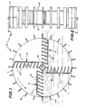
- FIGS 1 and 2 there is schematically depicted a device 10 to aerate and mix sewage.
- the device 10 consists generally of a rotatable housing 11 including two disc members 12 between which is located radially extending arms 13.
- the arms 13 extend radially outwardly from a central shaft 14 to which the disc members 12 and arms 13 are fixed so as to be rotatable thereby about the longitudinal axis of the shaft 14.
- Each arm 13 includes a base 15 from which extends a plurality of fins 16 so as to, in combination with the base 15 and discs 12, define a plurality of chambers 17.
- Located along the periphery of the housing 11 are a plurality of paddles 18 which aid in mixing the sewage.
- the housing and therefore arms 13 are rotated by the shaft 14 in an anticlockwise direction (relative to Figure 1).
- the arms 13 enter and leave the liquid 19
- air is delivered to below the liquid level by an arm 13 entering the liquid 19 since air would be trapped within the chamber 17.
- a portion of the liquid is retained in the chamber 17 and is allowed to spill therefrom as the arm is raised.
- the device in aerating liquid uses two operations. The first operation is delivery of air to below the liquid level, while the second operation is causing the liquid to spill from the chamber 17 thereby passing through air in returning to the body of the liquid 19.
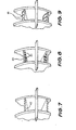
- the device 20 includes a generally circular housing 21 which is fixed to a driven shaft 22.
- the housing 21 includes two disc members 23 between which is located a plurality of fins 24 arranged in three sets 25, 26 and 27.
- the fins 24 of each of the sets 25, 26 and 27 lie generally along a cord of a circle defined by the housing 21.
- the fins 24 within each set 25, 26 or 27 would be parallel with the radially innermost fin defining an angle of about 5° with a radius extending from the shaft 22 and intersecting a radially innermost fin 24 at a position on the periphery of the housing 21.
- the fins 24 and disc members 23 define a plurality of chambers 28 which receive the liquid and air as the device 20 is rotated.
- the device 20 would be positioned with the liquid level passing through the shaft 22 with the housing 21 being rotated in an anticlockwise direction (relative to Figure 3).
- the chambers 28 would be caused to enter and leave the liquid thereby delivering air to below the liquid surface while lifting the liquid above the liquid level and causing the liquid to spill from within the chambers 28 thereby passing through air in returning to the body of the liquid.
- the housing 21 would be provided with a plurality of paddles 29 which aid in mixing the sewage as the housing 21 is rotated.
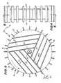
- FIGS 5 and 6 there is schematically depicted a device 30 which is adapted to aerate and mix sewage.
- the device 30 includes a housing 31 having two disc members 32 fixed to a shaft 33. Located within the housing 31 is a plurality of fins 34 which extend along cords of the circle defined by the housing 31.
- the fins 34 are arranged in four sets 35, 36, 37 and 38 with the fins 34 of each set being arranged generally parallel. Accordingly the fins 34 in combination with the disc members 32 define a plurality of chambers 39 which receive air or liquid to be mixed and aerated.
- the chambers 39 are caused to enter and leave the liquid thereby delivering air to below the liquid level while raising the liquid above the liquid level causing the liquid to spill from within the chambers 39 to be passed through air in being returned to the body of the liquid.
- the housing 31 would be provided with a plurality of paddles 40 which aid in mixing the sewage.
- each fin 42 would be serrated while with reference to Figure 8 each fin 43 would be provided with a plurality of holes 44 through which the air may pass. Additionally the serrations of Figure 7 and holes of Figure 8 would aid in causing disturbance of the liquid stream leaving the chambers 17, 28 and 29 thereby further enhancing the aeration process.
Abstract
A device (10) to aerate and mix sewage including a rotatable housing (11) within which is located a plurality of chambers (17), the housing (11) is rotated so that chambers (17) within the housing (11) pass from a submerged to an unsubmerged position thereby delivering air to below the liquid level while raising the liquid to a position to be delivered to the body of the liquid after passing through the air.
Description
- The present invention relates to devices to aerate and mix sewage or other liquids particularly liquids containing solids.
- It is a problem of known aeration and mixing devices that they are generally expensive to manufacture and operate and are not completely efficient in aerating sewage. Additionally these known devices, especially air compressors require considerable maintenance.
- It is an object of the present invention to ovecome or substantially ameliorate the above disadvantages.
- There is disclosed herein an aeration device for liquids comprising a rotatable housing to be rotated about a predetermined horizontal axis so that a portion of the housing is located below the liquid level, a plurality of chambers defined within said housing, each chamber having an opening allowing liquid to enter and leave the chamber as it passes between a submerged and unsubmerged position, and drive means to rotate said housing.
- A preferred form of the present invention will now be described by way of example with reference to the accompanying drawings, wherein:
- Figure 1 is a schematic side elevation of a sewage aeration and mixing device;
- Figure 2 is an end elevation of the device of Figure 1;
- Figure 3 is a schematic side elevation of a further device to mix and aerate sewage;
- Figure 4 is a schematic end elevation of the device of Figure 3;
- Figure 5 is a schematic side elevation of a further devices to aerate and mix sewage;
- Figure 6 is an end elevation of the device of Figure 5;
- Figures 7, 8 and 9 are schematic perspective views of portions of the aerating and mixing devices of Figures 1, 3 and 5.
- In Figures 1 and 2 there is schematically depicted a
device 10 to aerate and mix sewage. Thedevice 10 consists generally of a rotatable housing 11 including twodisc members 12 between which is located radially extendingarms 13. Thearms 13 extend radially outwardly from acentral shaft 14 to which thedisc members 12 andarms 13 are fixed so as to be rotatable thereby about the longitudinal axis of theshaft 14. Eacharm 13 includes abase 15 from which extends a plurality offins 16 so as to, in combination with thebase 15 anddiscs 12, define a plurality ofchambers 17. Located along the periphery of the housing 11 are a plurality ofpaddles 18 which aid in mixing the sewage. - In operation of the
device 10, the housing and thereforearms 13 are rotated by theshaft 14 in an anticlockwise direction (relative to Figure 1). As thearms 13 enter and leave theliquid 19, air is delivered to below the liquid level by anarm 13 entering theliquid 19 since air would be trapped within thechamber 17. Additionally as one of thearms 13 leaves theliquid 19, a portion of the liquid is retained in thechamber 17 and is allowed to spill therefrom as the arm is raised. Accordingly the device in aerating liquid uses two operations. The first operation is delivery of air to below the liquid level, while the second operation is causing the liquid to spill from thechamber 17 thereby passing through air in returning to the body of theliquid 19. - Turning now to Figures 3 and 4 wherein there is schematically depicted a
device 20 to aerate and mix sewage. Thedevice 20 includes a generallycircular housing 21 which is fixed to a drivenshaft 22. Thehousing 21 includes twodisc members 23 between which is located a plurality offins 24 arranged in threesets fins 24 of each of thesets housing 21. Preferably thefins 24 within eachset shaft 22 and intersecting a radiallyinnermost fin 24 at a position on the periphery of thehousing 21. Thefins 24 anddisc members 23 define a plurality ofchambers 28 which receive the liquid and air as thedevice 20 is rotated. Thedevice 20 would be positioned with the liquid level passing through theshaft 22 with thehousing 21 being rotated in an anticlockwise direction (relative to Figure 3). As thedevice 20 is rotated, thechambers 28 would be caused to enter and leave the liquid thereby delivering air to below the liquid surface while lifting the liquid above the liquid level and causing the liquid to spill from within thechambers 28 thereby passing through air in returning to the body of the liquid. Additionally thehousing 21 would be provided with a plurality ofpaddles 29 which aid in mixing the sewage as thehousing 21 is rotated. - In Figures 5 and 6 there is schematically depicted a
device 30 which is adapted to aerate and mix sewage. Thedevice 30 includes ahousing 31 having twodisc members 32 fixed to ashaft 33. Located within thehousing 31 is a plurality offins 34 which extend along cords of the circle defined by thehousing 31. Thefins 34 are arranged in foursets fins 34 of each set being arranged generally parallel. Accordingly thefins 34 in combination with thedisc members 32 define a plurality ofchambers 39 which receive air or liquid to be mixed and aerated. - As discussed previously, as the
device 30 is rotated, thechambers 39 are caused to enter and leave the liquid thereby delivering air to below the liquid level while raising the liquid above the liquid level causing the liquid to spill from within thechambers 39 to be passed through air in being returned to the body of the liquid. Additionally thehousing 31 would be provided with a plurality ofpaddles 40 which aid in mixing the sewage. - It is desirable to regulate the stream of
liquid leaving chambers 39 to enhance the aeration operation. In the embodiment of Figures 5 and 6 there is provided on the radial extremity of each fin a set ofprojections 41 which are more clearly depicted in Figure 9. These projections separate the main stream of liquid leaving thechambers 39 into three or more substreams. - It is also desirable to regulate the bubble size as air exits from the
chambers fin 42 would be serrated while with reference to Figure 8 eachfin 43 would be provided with a plurality ofholes 44 through which the air may pass. Additionally the serrations of Figure 7 and holes of Figure 8 would aid in causing disturbance of the liquid stream leaving thechambers
Claims (13)
1. An aeration device for liquids comprising a rotatable housing to be rotated about a predetermined horizontal axis so that a portion of the housing is located below the liquid level, a plurality of chambers defined within said housing, each chamber having an opening allowing liquid to enter and leave the chamber as it passes between a submerged and unsubmerged position, and drive means to rotate said housing.
2. The device of claim 1 wherein said housing includes a plurality of fins located in said housing so as to be rotated therewith and which extend outwardly with respect to the axis to thereby partly define said chamber.
3. The device of claim 2 wherein said fins extend along cords of a circle having its centre on said axis.
4. The device of claim 2 or 3 wherein each fin is located within a plane which is parallel to a plane containing said axis.
5. The device of claim 3 wherein said housing is circular and said fins generally extend along cords of the circular housing.
6. The device of claim 5 wherein said fins extend in planes parallel to said axis.
7. The device of claim 6 wherein said fins are arranged in groups with the fins within each group being parallel.
8. The device of claim 6 or 7 wherein said fins define an angle of 5° with a radius extending through the radially outer end of the radially innermost fin.
9. The device of claims 1 to 8 wherein the outer extremity of the fins are provided with deformations.
10. The device of claim 9 wherein the deformations are a plurality of holes extending through the fins.
11. The device of claim 9 wherein the deformations are a plurality of projections extending from the plane of the fins.
12. The device of claim 9 wherein the deformations are serrations formed on the radially outer end of the fins.
13. A device to aerate and mix sewage substantially as hereinbefore described with reference to the accompanying drawings.
Applications Claiming Priority (2)
| Application Number | Priority Date | Filing Date | Title |
|---|---|---|---|
| AU9136/81 | 1981-06-02 | ||
| AUPE913681 | 1981-06-02 |
Publications (1)
| Publication Number | Publication Date |
|---|---|
| EP0067028A1 true EP0067028A1 (en) | 1982-12-15 |
Family
ID=3769088
Family Applications (1)
| Application Number | Title | Priority Date | Filing Date |
|---|---|---|---|
| EP19820302810 Withdrawn EP0067028A1 (en) | 1981-06-02 | 1982-06-01 | Apparatus to aerate and mix sewage or other fluids containing solids |
Country Status (5)
| Country | Link |
|---|---|
| EP (1) | EP0067028A1 (en) |
| JP (1) | JPS586289A (en) |
| AU (1) | AU8438482A (en) |
| BR (1) | BR8203232A (en) |
| ZA (1) | ZA823852B (en) |
Cited By (3)
| Publication number | Priority date | Publication date | Assignee | Title |
|---|---|---|---|---|
| EP0131236B1 (en) * | 1983-07-09 | 1987-02-04 | Water Engineering and Plant Construction GtA reg.Trust | Mechanical and biological installation, and process for waste water purification |
| WO1987007886A1 (en) * | 1986-06-19 | 1987-12-30 | Pielkenrood-Vinitex B.V. | A method and a device for introducing a gas into a liquid |
| WO1989001915A1 (en) * | 1987-08-28 | 1989-03-09 | Niels Vestergaard | Aeration wheel and plant for aeration of water |
Citations (4)
| Publication number | Priority date | Publication date | Assignee | Title |
|---|---|---|---|---|
| DE2218165A1 (en) * | 1971-04-15 | 1972-11-02 | O.C.P. S.A., Brüssel | Runner for ventilation, especially for enriching wastewater with oxygen |
| DE2615465A1 (en) * | 1975-04-18 | 1976-10-28 | Friedrich Rohrhofer | PROCEDURE AND EQUIPMENT FOR VENTILATION OF ANIMAL EXECUTION (GUELLE) |
| EP0005553A1 (en) * | 1978-05-22 | 1979-11-28 | Theo Stähler | Device for the conversion of materials present in waste water and waste water sludges |
| EP0017064A1 (en) * | 1979-03-27 | 1980-10-15 | Theo Stähler | Apparatus for the aeration of waste water or sludge |
-
1981
- 1981-06-02 AU AU84384/82A patent/AU8438482A/en not_active Abandoned
-
1982
- 1982-06-01 EP EP19820302810 patent/EP0067028A1/en not_active Withdrawn
- 1982-06-02 ZA ZA823852A patent/ZA823852B/en unknown
- 1982-06-02 BR BR8203232A patent/BR8203232A/en unknown
- 1982-06-02 JP JP57094649A patent/JPS586289A/en active Pending
Patent Citations (4)
| Publication number | Priority date | Publication date | Assignee | Title |
|---|---|---|---|---|
| DE2218165A1 (en) * | 1971-04-15 | 1972-11-02 | O.C.P. S.A., Brüssel | Runner for ventilation, especially for enriching wastewater with oxygen |
| DE2615465A1 (en) * | 1975-04-18 | 1976-10-28 | Friedrich Rohrhofer | PROCEDURE AND EQUIPMENT FOR VENTILATION OF ANIMAL EXECUTION (GUELLE) |
| EP0005553A1 (en) * | 1978-05-22 | 1979-11-28 | Theo Stähler | Device for the conversion of materials present in waste water and waste water sludges |
| EP0017064A1 (en) * | 1979-03-27 | 1980-10-15 | Theo Stähler | Apparatus for the aeration of waste water or sludge |
Cited By (4)
| Publication number | Priority date | Publication date | Assignee | Title |
|---|---|---|---|---|
| EP0131236B1 (en) * | 1983-07-09 | 1987-02-04 | Water Engineering and Plant Construction GtA reg.Trust | Mechanical and biological installation, and process for waste water purification |
| WO1987007886A1 (en) * | 1986-06-19 | 1987-12-30 | Pielkenrood-Vinitex B.V. | A method and a device for introducing a gas into a liquid |
| US4904420A (en) * | 1986-06-19 | 1990-02-27 | Pielkenrood Vinitex B.V. | Method and a device for introducing a gas into a liquid |
| WO1989001915A1 (en) * | 1987-08-28 | 1989-03-09 | Niels Vestergaard | Aeration wheel and plant for aeration of water |
Also Published As
| Publication number | Publication date |
|---|---|
| ZA823852B (en) | 1983-04-27 |
| BR8203232A (en) | 1983-05-17 |
| AU8438482A (en) | 1982-12-09 |
| JPS586289A (en) | 1983-01-13 |
Similar Documents
| Publication | Publication Date | Title |
|---|---|---|
| US5658076A (en) | Apparatus for storing and handling waste water slurries | |
| US4297214A (en) | Aerator | |
| US3341450A (en) | Gasification apparatus and method | |
| GB2082077A (en) | Surface aeration | |
| JPS6253213B2 (en) | ||
| US4680119A (en) | Apparatus for introducing a gas into a liquid | |
| US4151231A (en) | Rotary surface aerators | |
| EP1015102B1 (en) | Improved mixing and aerating apparatus | |
| EP0067028A1 (en) | Apparatus to aerate and mix sewage or other fluids containing solids | |
| US4551285A (en) | Flotation machine and aeration impeller | |
| CA1143078A (en) | Apparatus and method for mixing gases with liquids | |
| US3796414A (en) | Aerator | |
| EP0027911B1 (en) | Apparatus for contacting liquid with a gas | |
| US4074953A (en) | Surface aerator | |
| JP2001219046A (en) | Stirring apparatus | |
| US6029955A (en) | Counterbalanced dual submarine-type liquid mixer pairs | |
| PT736322E (en) | DEVICE FOR INSERTING A GAS IN A LIQUID | |
| KR20190025590A (en) | Containers for particle generation AND Particle generation method Using them | |
| US4336144A (en) | Method for mixing gases with liquids | |
| DE8605277U1 (en) | Mixer for liquid containers | |
| EP0612696A1 (en) | Method and device for controlled motion of water in water basins | |
| CA1057431A (en) | Rotary surface aerators | |
| US3700103A (en) | Recovery of minerals | |
| US4490260A (en) | Mechanical conditioning and flocculation of liquids | |
| EP4085994A1 (en) | Mixing device |
Legal Events
| Date | Code | Title | Description |
|---|---|---|---|
| PUAI | Public reference made under article 153(3) epc to a published international application that has entered the european phase |
Free format text: ORIGINAL CODE: 0009012 |
|
| AK | Designated contracting states |
Designated state(s): AT BE CH DE FR GB IT LI LU NL SE |
|
| STAA | Information on the status of an ep patent application or granted ep patent |
Free format text: STATUS: THE APPLICATION IS DEEMED TO BE WITHDRAWN |
|
| 18D | Application deemed to be withdrawn |
Effective date: 19831123 |