EP0066928B1 - X-ray generator, generation method and x-ray generator for carrying out this method - Google Patents
X-ray generator, generation method and x-ray generator for carrying out this method Download PDFInfo
- Publication number
- EP0066928B1 EP0066928B1 EP82200653A EP82200653A EP0066928B1 EP 0066928 B1 EP0066928 B1 EP 0066928B1 EP 82200653 A EP82200653 A EP 82200653A EP 82200653 A EP82200653 A EP 82200653A EP 0066928 B1 EP0066928 B1 EP 0066928B1
- Authority
- EP
- European Patent Office
- Prior art keywords
- ray
- filament
- tube
- filament current
- memory
- Prior art date
- Legal status (The legal status is an assumption and is not a legal conclusion. Google has not performed a legal analysis and makes no representation as to the accuracy of the status listed.)
- Expired
Links
Images

Classifications
-
- H—ELECTRICITY
- H05—ELECTRIC TECHNIQUES NOT OTHERWISE PROVIDED FOR
- H05G—X-RAY TECHNIQUE
- H05G1/00—X-ray apparatus involving X-ray tubes; Circuits therefor
- H05G1/08—Electrical details
- H05G1/70—Circuit arrangements for X-ray tubes with more than one anode; Circuit arrangements for apparatus comprising more than one X ray tube or more than one cathode
-
- H—ELECTRICITY
- H05—ELECTRIC TECHNIQUES NOT OTHERWISE PROVIDED FOR
- H05G—X-RAY TECHNIQUE
- H05G1/00—X-ray apparatus involving X-ray tubes; Circuits therefor
- H05G1/08—Electrical details
- H05G1/26—Measuring, controlling or protecting
- H05G1/30—Controlling
- H05G1/34—Anode current, heater current or heater voltage of X-ray tube
Definitions
- the invention relates to a method for operating an x-ray system with an x-ray generator for a plurality of x-ray tubes with a device for setting a quiescent heating current for a filament of an x-ray tube in recording breaks and with a high-voltage generator, and to an x-ray generator which is intended for this method.
- the preparation of a recording is usually preceded by a preparatory phase in which the temperature of the cathode filament is brought to the value required for the recording, but in which the tube voltage is not yet switched on, so that no radiation is generated yet.
- This preparation phase can be shortened by overheating (boosting) the filament, but not significantly if the danger of the filament burning through is to be avoided.
- it is therefore known to feed a quiescent heating current into the filament of the x-ray tube to be used for a later recording during the breaks in operation ("stand-by"). This increases the filament temperature and thus the ohmic resistance of the filament, so that the final temperature of the filament can be reached much faster in a subsequent preparation phase.
- the quiescent heating current is generally selected so that it has just the right value for the filaments with the highest resistance value. This means that when connecting X-ray tubes with low-resistance filaments, relatively long preparation times are required in order to achieve the desired thread temperature for the recording case.
- the object of the present invention is to design a method of the type mentioned in the introduction such that the final temperature of the filament can be reached more quickly in the preparation phase and to provide an X-ray generator for carrying out this method.
- the X-ray generator for carrying out this method which is provided with a tube selector for selecting an X-ray tube, a focus selector and with a heating current actuator for setting the heating current to which a stored heating current is applied, is characterized in that a non-volatile digital memory arrangement is provided with Several Zetlen is provided for different quiescent heating current values, and that the tube selection device is coupled with a device for addressing and calling up the memory arrangement so that for each tube heating filament selected by the tube selection device and the focus selector, a particular memory cell is called up and its content is applied to a heating current actuator becomes.
- the X-ray generator according to the invention has a high-voltage generator 1, to which one of several - in the exemplary embodiment three - X-ray tubes 14, 15, 16 can be connected via a high-voltage switch 2.
- Each of the X-ray tubes has two filaments 4, 4 ', 5, 5', 6, 6 '.
- the high-voltage generator therefore comprises, in addition to a high-voltage transformer for generating the tube voltage, two heating current transformers, the primary windings of which can be switched in a known manner by focus selectors and the secondary windings of which supply the heating currents for the filaments of an X-ray tube.
- the heating current transformers can be part of a heating current control circuit 3, which consists of a comparison element 31, which compares the actual value of the heating current with a desired value, and a control amplifier 32, which amplifies the control deviation and feeds it to the connected heating current transformer, so that the The actual value of the heating current largely corresponds to its setpoint.
- the setpoint of the heating current is supplied by a digital-to-analog converter 7, which is connected to an intermediate store 8, which in turn is coupled to a store 9 designed as a read-only memory (PROM) via a changeover switch 10.
- the read-only memory 9 contains a first memory area 91, in which heating current values are stored, as is known per se from DE-A-27 03 420, and a second memory area with memory cells 94, 95 and 96, in which the quiescent heating current values for the three X-ray tubes 4 , 5 and 6 (two quiescent heating current values for each X-ray tube) are stored.
- the changeover switch 10 and the high-voltage changeover switch 2 used for the selection of the x-ray tube and the focus selector are coupled to one another via a control unit, so that the memory cells 94 for the x-ray tube 4, the memory cells 95 for the x-ray tube 5 and the memory cells for the x-ray tube 6 96 take effect, in which the quiescent heating current values measured as described above are stored for each filament. This ensures that at the beginning of the preparation time the filament has such a temperature that only a relatively short period of time is required to reach the final temperature. If the preparation phase is then initiated - which is also signaled to the control unit 11 via the input 12 - there is a switchover to the memory area 91, in which the heating current required for a recording is stored for the X-ray tube in question.
- the control unit 11 is preferably implemented with the aid of a microcomputer, and the read-only memory 9 is accessed using a bus line which connects the microcomputer with the read-only memory 9 and the buffer memory 8.
- the control unit 11 and the memory 9 are shown in more detail in FIG. 2.
- the controller 11 includes a microprocessor 20 (Intel 8086), a clock generator 21 (8284A), an interrupt control circuit 22 (8259A), an eight-way latch 23 (8282) and some other circuitry to be described later.
- the microprocessor 20 comprises an address / data bus 24 which connects the catch flip-flop 23, the memory 9 '(2732, 2118) and the interrupt control circuit 22 to one another.
- An address generated by the microprocessor 20 is temporarily stored in the buffer memory 23 when a key signal occurs, which is fed to the key input STB of this circuit from the microprocessor 20 via a control line of the bus 25.
- the address can be given on the address bus 26 by an output enable signal which is received by the circuit 23 via the control bus 25.
- the signals on the control bus 25 or the address bus 26 are applied to a system bus 27 via driver circuits 28a and 28c (74LS244).
- the memory 9 ' is with the data bus 24 and
- the read-only memory 9 or a read-write memory 9a is activated via a memory decoder 29 (N82S137).
- the memory decoder 29 receives an address or part thereof from the latch 23 and also a further control signal which indicates whether an input signal is received or an output signal on the system bus 27 via a bidirectional bus driver 28d ( 8286) is to be delivered.
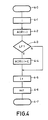
- the quiescent current operation of the x-ray generator is initiated by a signal at the interrupt input 12 which, via the interrupt control circuit 22, activates the microprocessor, which at this moment could be in a waiting routine (step 4-0 of the flow chart of FIG. 4).
- the microprocessor 20 reads the number i assigned to the selected x-ray tube and the selected filament of this x-ray tube by giving the assigned address via the catch memory and the bus driver circuit 28 to the system bus 27 and the data via the driver circuit 28d record (step 4-1).
- the position of the switch 2 is queried via an input multiplex circuit 40 (HEF-4512B), which receives the address of an input to be queried via a bus 41 and an output signal (“HIGH •) the output line 42 provides when said input is connected to + V via the switch 2 '.
- the switch 2 ' is mechanically connected to the switch 2, the position of which is to be queried.
- the microprocessor 20 selects the address (ADR (i)) of the quiescent heating current value table which is stored in the memory 9. The microprocessor 20 then checks which filament has been selected (large focus (LF) for large tube current, small focus for small tube current - step 4-3). If the large focus is used, the tube number i is increased by a fixed value C (step 4-4). If the small focus is used, step 4-4 is skipped. The address generated in this way is temporarily stored in the buffer memory 23 and the quiescent heating current value can be read out from the memory 9 (step 4-5). As can be seen from this, the switch 10 (FIG. 1) is formed by the catch memory 23 and the decoder 29, respectively.
- the quiescent heating current value is fed via the driver circuit 28d and the system bus 27 into the buffer memory 8 (4516 - see FIG. 3) and temporarily stored therein, the inputs of which are connected to the system bus 27 are connected.
- the outputs of the buffer 8 are connected to the digital-to-analog converter 7, the output of which is connected to the quiescent heating current control circuit 3.
- the x-ray generator then enters the preparation phase (step 4-7).
- the quiescent heating current values can be assigned individually to a tube Memory cells (94 ... 96) can be programmed, extensions being possible by adding storage units, or they can be programmed in collective memories which are created for all tube types which can be connected to the generator, the call being made by programming the control unit or the microcomputer the stored values and their assignment to the connected X-ray tubes.
Landscapes
- Health & Medical Sciences (AREA)
- General Health & Medical Sciences (AREA)
- Toxicology (AREA)
- X-Ray Techniques (AREA)
Description
Die Erfindung bezieht sich auf ein Verfahren zum Betrieb einer Röntgenanlage mit einem Röntgenstrahlengenerator für mehrere Röntgenröhren mit einer Einrichtung zum Einstellen eines Ruheheizstromes für einen Heizfaden einer Röntgenröhre in Aufnahmepausen und mit einem Hochspannungserzeuger sowie auf einen Röntgenstrahlengenerator, der dür dieses Verfahren bestimmt ist.The invention relates to a method for operating an x-ray system with an x-ray generator for a plurality of x-ray tubes with a device for setting a quiescent heating current for a filament of an x-ray tube in recording breaks and with a high-voltage generator, and to an x-ray generator which is intended for this method.
Der Anfertigung einer Aufnahme geht in der Regel eine Vorbereitungsphase voraus, in der u.a. die Temperatur des Kathoden-Heizfadens auf den für die Aufnahme erforderlichen Wert gebracht wird, in der jedoch die Röhrenspannung noch nicht eingeschaltet ist, so daß noch keine Strahlung erzeugt wird. Diese Vorbereitungsphase kann durch ein Überheizen (Boosten) des Heizfadens zwar abgekürzt werden, jedoch nicht wesentlich, wenn die Gefahr des Durchbrennens des Heizfadens vermieden werden soll. Um die Vorbereitungsphase abzukürzen, ist es daher bekannt, in den Betriebspausen (« Stand-by") in den Heizfaden der für eine spätere Aufnahme zu verwendenden Röntgenröhre einen Ruheheizstrom einzuspeisen. Dadurch wird die Heizfadentemperatur und damit auch der ohmsche Widerstand des Heizfadens erhöht, so daß in einer anschließenden Vorbereitungsphase die Endtemperatur des Heizfadens wesentlich schneller erreicht werden kann.The preparation of a recording is usually preceded by a preparatory phase in which the temperature of the cathode filament is brought to the value required for the recording, but in which the tube voltage is not yet switched on, so that no radiation is generated yet. This preparation phase can be shortened by overheating (boosting) the filament, but not significantly if the danger of the filament burning through is to be avoided. In order to shorten the preparation phase, it is therefore known to feed a quiescent heating current into the filament of the x-ray tube to be used for a later recording during the breaks in operation ("stand-by"). This increases the filament temperature and thus the ohmic resistance of the filament, so that the final temperature of the filament can be reached much faster in a subsequent preparation phase.
Werden mit einem Röntgenstrahlengenerator mehrere Röntgenröhren mit unterschiedlichen Heizfäden betrieben, dann ist der Ruheheizstrom im allgemeinen so gewählt, daß er für die Heizfäden mit dem höchsten Widerstandswert gerade den richtigen Wert hat. Dies führt dazu, daß beim Anschluß von Röntgenröhren mit niederohmigen Heizfäden relativ lange Vorbereitungszeiten erforderlich sind, um für den Aufnahmefall die gewünschte Fadentempertur zu erreichen.If several X-ray tubes with different filaments are operated with an X-ray generator, the quiescent heating current is generally selected so that it has just the right value for the filaments with the highest resistance value. This means that when connecting X-ray tubes with low-resistance filaments, relatively long preparation times are required in order to achieve the desired thread temperature for the recording case.
Aufgabe der vorliegenden Erfindung ist es, ein Verfahren der eingangs genannten Art so auszugestalten, daß in derVorbereitungsphase die Endtemperatur des Heizfadens schneller erreicht werden kann und einen Röntgenstrahlengenerator zur Durchführung dieses Verfahrens zu schaffen.The object of the present invention is to design a method of the type mentioned in the introduction such that the final temperature of the filament can be reached more quickly in the preparation phase and to provide an X-ray generator for carrying out this method.
Diese Aufgabe wird erfindungsgemäß dadurch gelöst, daß mehrere Ruheheizstromwerte gespeichert sind, die verschiedenen Röntgenröhrenheizfäden zugeordnet sind, und daß der einer an den Hochspannungserzeuger angeschlossenen Röntgenröhre zugeordnete Ruheheizstromwert für den eingeschalteten Heizfaden aufgerufen und eingestellt wird. Demgemäß ist der Röntgenstrahlengenerator zur Durchführung dieses Verfahrens, der mit einer Röhrenwähleinrichtung zum Wählen einer Röntgenröhre, einem Fokuswähler und mit einem Heizstrom-Stellglied zum Einstellen des Heizstromes versehen ist, das von einem gespeicherten Heizstrom beaufschlag wird, dadurch gekennzeichnet, daß eine nichtflüchtige digitale Speicheranordnung mit mehreren Zetlen für unterschiedliche Ruheheizstromwerte vorgesehen ist, und daß die Röhrenwähleinrichtung mit einer Einrichtung zum Adressieren und Aufruf der Speicheranordnung so gekoppelt ist, daß für jeden durch die Röhrenwähleinrichtung und den Fokuswähler gewählten Röhrenheizfaden jeweils eine bestimmte Speicherzelle aufgerufen und mit ihrem Inhalt ein Heizstrom-Stellglied beaufschlagt wird.This object is achieved in that several quiescent heating current values are stored which are assigned to different X-ray tube filaments, and that the quiescent heating current value assigned to an X-ray tube connected to the high-voltage generator is called up and set for the switched-on filament. Accordingly, the X-ray generator for carrying out this method, which is provided with a tube selector for selecting an X-ray tube, a focus selector and with a heating current actuator for setting the heating current to which a stored heating current is applied, is characterized in that a non-volatile digital memory arrangement is provided with Several Zetlen is provided for different quiescent heating current values, and that the tube selection device is coupled with a device for addressing and calling up the memory arrangement so that for each tube heating filament selected by the tube selection device and the focus selector, a particular memory cell is called up and its content is applied to a heating current actuator becomes.
Die Erfindung wird nachstehend anhand der Zeichnung näher erläutert. Es zeigen
Figur 1 ein Blockdiagramm eines erfindungsgemäßen Röntgenstrahlengenerators,Figur 2 ein Blockdiagramm des Steuerwerks und des Speichers des in Fig. 1 dargestellten Röntgenstrahlengenerators,Figur 3 eine weitere Einzelheit des Röntgenstrahlengenerators nach Fig. 1, undFigur 4 Flußdiagramme des Betriebes des Röntgenstrahlengenerators und seiner Steuerung.
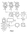
- FIG. 1 shows a block diagram of an X-ray generator according to the invention,
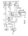
- FIG. 2 shows a block diagram of the control unit and the memory of the X-ray generator shown in FIG. 1,
- 3 shows a further detail of the X-ray generator according to FIG. 1, and
- Figure 4 is a flow diagram of the operation of the X-ray generator and its control.
Der erfindungsgemäße Röntgenstrahlengenerator besitzt einen Hochspannungserzeuger 1, an den eine von mehreren - im Ausführungsbeispiel drei - Röntgenröhren 14, 15, 16 über einen Hochspannungs-Umschalter 2 angeschlossen werden kann. Jede der Röntgenröhren besitzt zwei Heizfäden 4, 4', 5, 5', 6, 6'. Der Hochspannungserzeuger umfaßt daher neben einem Hochspannungstransformator zur Erzeugung der Röhrenspannung zwei Heizstromtransformatoren, deren Primärwicklungen in bekannter Weise durch Fokuswähler umschaltbar sind und deren Sekundärwicklungen die Heizströme für die Heizfäden einer Röntgenröhre liefern. Die nicht näher dargestellten Heizstromtransformatoren können Teil eines Heizstrom-Regelkreises 3 sein, der aus einem Vergleichsglied 31 besteht, das den Iswert des Heizstromes mit einem Sollwert vergleicht, und aus einem Regleverstärker 32, der die Regelabweichung verstärkt und dem angeschalteten Heizstromtransformator zuführt, so daß der Istwert des Heizstromes weitgehend seinem Sollwert entspricht.The X-ray generator according to the invention has a high-
Der Sollwert des Heizstromes wird von einem Digital-Analog-Wandler 7 geliefert, der mit einem Zwischenspeicher 8 verbunden ist, der seinerseits mit einem als Festwertspeicher (PROM) ausgebildeten Speicher 9 über einen Umschalter 10 gekoppelt ist. Der Festwertspeicher 9 enthält einen ersten Speicherbereich 91, in dem Heizstromwerte gespeichert sind, wie an sich aus der DE-A-27 03 420 bekannt, und einen zweiten Speicherbereich mit Speicherzellen 94, 95 und 96, in denen die Ruheheizstromwerte für die drei Röntgenröhren 4, 5 und 6 (für jede Röntgenröhre zwei Ruheheizstromwerte) gespeichert sind.The setpoint of the heating current is supplied by a digital-to-
Diese Ruheheizstromwerte sind für jede Röntgenröhre und jeden ihrer Heizfäden so gewählt, daß beim Betrieb der Röntgenröhre mit diesem Heizstrom und beim Anliegen einer Hochspannung (z. B. 40 kV) an der Röntgenröhre ein bestimmter Emissions-Höchstwert eingehalten wird, z. B. 20 liA. Diese Festlegung ist erforderlich, um auch in dem Fall, daß für den Aufnahmebetrieb der dem großen Brennfleck zugeordnete Heizfaden vorgewählt wird, während mit dem Heizfaden für den kleinen Brennfleck durchleuchtet wird, zu gewährleisten, daß die Bildqualität und die Regeleigenschaften des Durchleuchtungs-Regelkreises durch die zusätzliche Emission des mit dem Ruheheizstrom beaufschlagten Heizfadens nicht merklich beeinträchtigt werden.These quiescent heating current values are chosen for each X-ray tube and each of its filaments, that when the X-ray tube is operated with this heating current and when a high voltage (e.g. 40 kV) is applied to the X-ray tube, a certain maximum emission value is observed, e.g. B. 20 li A. This definition is necessary to ensure that the image quality and the control properties, even in the event that the filament associated with the large focal spot is preselected for the recording operation, while the filament is illuminated for the small focal spot of the fluoroscopic control circuit are not noticeably impaired by the additional emission of the filament charged with the quiescent heating current.
Der Umschalter 10 und der zur Wahl der Röntgenröhre dienende Hochspannungs-Umschalter 2 sowie der nicht dargestellte Fokuswähler sind über ein Steuerwerk miteinander gekoppelt, so daß für die Röntgenröhre 4 die Speicherzellen 94, für die Röntgenröhre 5 die Speicherzellen 95 und für die Röntgenröhre 6 die Speicherzellen 96 wirksam werden, in denen die wie vorstehend beschrieben gemessenen Ruheheizstromwerte für jeden Heizfaden gespeichert sind. Dadurch ist sichergestellt, daß bei Beginn der Vorbereitungszeit der Heizfaden eine solche Temperatur hat, daß für das Erreichen der Endtemperatur nur noch ein relativ kurzer Zeitraum erforderlich ist. Wird dann die Vorbereitungsphase eingeleitet - was über den Eingang 12 auch dem Steuerwerk 11 signalisiert wird - erfolgt eine Umschaltung auf den Speicherbereich 91, in dem der für eine Aufnahme erforderliche Heizstrom für die betreffende Röntgenröhre gespeichert ist.The
Das Steuerwerk 11 wird vorzugsweise mit Hilfe eines Microcomputers realisiert, und der Zugriff auf den Festwertspeicher 9 erfolgt dabei mit Hilfe einer Busleitung, die den Microcomputer mit dem Festwertspeicher 9 und dem Zwischenspeicher 8 verbindet.The
Das Steuerwerk 11 und der Speicher 9 sind in Fig. 2 näher dargestellt. Das Steuerwerk 11 umfaßt einen Microprozessor 20 (Intel 8086), einen Taktgenerator 21 (8284A), eine Interrupt-Steuerschaltung 22 (8259A), einen Achtfach-Auffangspeicher 23 (8282) und einige weitere Schaltungen, die später beschrieben werden. Der Microprozessor 20 umfaßt einen Adreß/Daten-Bus 24, der das Auffang-Flip-Flop 23, den Speicher 9' (2732, 2118) und die Interrupt-Steuerschaltung 22 miteinander verbindet. Eine vom Microprozessor 20 erzeugte Adresse wird in dem Auffangspeicher 23 beim Auftreten eines Tastsignals zwischengespeichert, das dem Tasteingang STB dieser Schaltung vom Microprozessor 20 über eine Steuerleitung des Bus 25 zugeführt wird. Die Adresse kan auf den Adreß-Bus 26 durch ein Ausgangs-Freigabesignal gegeben werden, das von der Schaltung 23 über den Steuer-Bus 25 empfangen wird. Die Signale auf dem Steuer-Bus 25 oder dem Adreß-Bus 26 werden über Treiberschaltungen 28a und 28c (74LS244) auf einen System-Bus 27 gegeben. Der Speicher 9' ist mit dem Daten-Bus 24 und demThe
Adreß-Bus 26 verbunden. Über einen Speicher-Decoder 29 (N82S137) wird der Festwertspeicher 9 oder ein Schreib-Lese-Speicher 9a aktiviert. Im Betrieb empfängt der Speicher-Decoder 29 von dem Auffangspeicher 23 eine Adresse bzw. ein Teil davon und ebenso ein weiteres Steuersignal, das angibt, ob ein Eingangssignal empfangen oder ein Ausgangssignal auf den System-Bus 27 über einen Zweirichtungs-Bus-Treiber 28d (8286) abgegeben werden soll. Der Ruhestrombetrieb des Röntgenstrahlengenerators wird durch ein Signal an dem Interrupt-Eingang 12 eingeleitet, das über die Interrupt-Steuerschaltung 22 den Microprozessor aktiviert, der in diesem Augenblick in einer Warteroutine (Schritt 4-0 des Flußdiagramms der Fig.4) sein könnte. Der Microprozessor 20 liest die der ausgewählten Röntgenröhre zugeordnete Nummer i und den ausgewählten Heizfaden dieser Röntgenröhre, indem er die zugeordnete Adresse über den Auffangspeicher und die Bus-Treiber-Schaltung 28 auf den System-Bus 27 gibt und die Daten über die Treiber-Schaltung 28d aufnimmt (Schritt 4-1).
Wie aus Fig. ersichtlich, wird zu diesem Zweck die Position des Schalters 2 über eine Eingangs-Multiplex-Schaltung 40 (HEF-4512B) abgefragt, die über einen Bus 41 die Adresse eines abzufragenden Einganges empfängt und ein Ausgangssignal (« HIGH •) auf der Ausgangsleitung 42 liefert, wenn der besagte Eingang über den Schalter 2' mit + V verbunden ist. Der Schalter 2' ist mechanisch mit dem Schalter 2 verbunden, dessen Position abgefragt werden soll.For this purpose, as can be seen from FIG. 1, the position of the
Der Microprozessor 20 wählt auf der Basis der Ziffer i die Adresse (ADR(i)) der Ruheheizstromwert-Tabelle, die in dem Speicher 9 gespeichert ist. Anschließend überprüft der Microprozessor 20, welcher Heizfaden gewählt worden ist (großer Fokus (LF) für großen Röhrenstrom, kleiner Fokus für kleinen Röhrenstrom - Schritt 4-3). Wenn der große Fokus benutzt wird, wird die Röhrennummer i um einen festen Wert C erhöht (Schritt 4-4). Wenn der kleine Fokus benutzt wird, wird der Schritt 4-4 übersprungen. Die so erzeugte Adresse wird im Auffangspeicher 23 zwischengespeichert und der Ruheheizstromwert kann aus dem Speicher 9 ausgelesen werden (Schritt 4-5). Wie sich daraus ergibt, wird der Schalter 10 (Fig. 1) jeweils durch den Auffangspeicher 23 und den Decoder 29 gebildet. Während des nächsten Schrittes (4-6) wird der Ruheheizstromwert über die Treiber-Schaltung 28d und den System-Bus 27 in den Zwischenspeicher 8 (4516 - vgl. Fig. 3) gegeben und darin zwischengespeichert, dessen Eingänge mit dem System-Bus 27 verbunden sind. Die Ausgänge des Zwischenspeichers 8 sind mit dem Digital-Analog-Wandler 7 verbunden, dessen Ausgang mit dem Ruheheizstrom-Regelkreis 3 verbunden ist. Der Röntgenstrahlengenerator tritt dann in die Vorbereitungsphase (Schritt 4-7) ein.Based on the number i, the
Die Ruheheizstromwerte können dabei in einzelnen, jeweils einer Röhre zugeordneten Speicherzellen (94...96) programmiert sein, wobei Erweiterungen durch Hinzufügen von Speichereinheiten möglich sind, oder sie können in Sammelspeichern programmiert sein, die für alle an den Generator anschließbaren Röhrentypen erstellt werden, wobei durch Programmieren des Steuerwerkes bzw. des Microcomputers der Aufruf der gespeicherten Werte und ihre Zuordnung zu den angeschlossenen Röntgenröhren festgelegt wird.The quiescent heating current values can be assigned individually to a tube Memory cells (94 ... 96) can be programmed, extensions being possible by adding storage units, or they can be programmed in collective memories which are created for all tube types which can be connected to the generator, the call being made by programming the control unit or the microcomputer the stored values and their assignment to the connected X-ray tubes.
Claims (2)
Applications Claiming Priority (2)
| Application Number | Priority Date | Filing Date | Title |
|---|---|---|---|
| DE3122185 | 1981-06-04 | ||
| DE19813122185 DE3122185A1 (en) | 1981-06-04 | 1981-06-04 | METHOD FOR OPERATING AN X-RAY GENERATOR AND X-RAY GENERATOR FOR CARRYING OUT THIS METHOD |
Publications (2)
| Publication Number | Publication Date |
|---|---|
| EP0066928A1 EP0066928A1 (en) | 1982-12-15 |
| EP0066928B1 true EP0066928B1 (en) | 1985-09-18 |
Family
ID=6133892
Family Applications (1)
| Application Number | Title | Priority Date | Filing Date |
|---|---|---|---|
| EP82200653A Expired EP0066928B1 (en) | 1981-06-04 | 1982-05-28 | X-ray generator, generation method and x-ray generator for carrying out this method |
Country Status (4)
| Country | Link |
|---|---|
| EP (1) | EP0066928B1 (en) |
| JP (1) | JPS57210600A (en) |
| CA (1) | CA1193751A (en) |
| DE (2) | DE3122185A1 (en) |
Families Citing this family (4)
| Publication number | Priority date | Publication date | Assignee | Title |
|---|---|---|---|---|
| FR2598583A1 (en) * | 1986-05-06 | 1987-11-13 | Thomson Cgr | RADIOLOGY INSTALLATION WITH COMMUNICATION NETWORK |
| DE3741109A1 (en) * | 1987-12-04 | 1989-06-15 | Thomson Cgr | X-RAY DIAGNOSTIC APPARATUS |
| DE4416556A1 (en) * | 1994-05-11 | 1995-11-16 | Philips Patentverwaltung | X-ray generator |
| CN105769232B (en) | 2016-02-22 | 2018-01-12 | 上海联影医疗科技有限公司 | The X-ray tube filament pre-heating method of CT equipment and pre- heater circuit |
Family Cites Families (10)
| Publication number | Priority date | Publication date | Assignee | Title |
|---|---|---|---|---|
| GB829521A (en) * | 1958-04-11 | 1960-03-02 | Picker X Ray Corp Waite Mfg | Improvements relating to x-ray apparatus |
| JPS4310518Y1 (en) * | 1965-07-31 | 1968-05-08 | ||
| JPS4510429Y1 (en) * | 1967-02-20 | 1970-05-13 | ||
| JPS5621385Y2 (en) * | 1973-05-29 | 1981-05-20 | ||
| DE2539898C2 (en) * | 1975-09-08 | 1982-06-03 | Siemens AG, 1000 Berlin und 8000 München | X-ray diagnostic apparatus with an adjusting means for the control circuit containing the X-ray tube heating current for a recording parameter dependent on the X-ray tube current |
| DE2542016A1 (en) * | 1975-09-20 | 1977-03-24 | Philips Patentverwaltung | Control circuit for X-ray tube exposure current - has resistor switched between two HV generators with voltage drop proportional to actual value of exposure current |
| DE2703420C2 (en) * | 1977-01-28 | 1985-11-21 | Philips Patentverwaltung Gmbh, 2000 Hamburg | Method for setting the tube current flowing through an X-ray tube and circuit arrangement for carrying out the method |
| JPS5424587A (en) * | 1977-07-27 | 1979-02-23 | Toshiba Corp | X-ray unit |
| EP0025688A3 (en) * | 1979-09-13 | 1981-05-27 | Pfizer Inc. | Process for rapidly achieving stabilized X-ray emission from an X-ray tube |
| JPS6459720A (en) * | 1987-08-28 | 1989-03-07 | Mitsubishi Metal Corp | Manufacture of superconductive ceramic processing material |
-
1981
- 1981-06-04 DE DE19813122185 patent/DE3122185A1/en not_active Withdrawn
-
1982
- 1982-05-28 DE DE8282200653T patent/DE3266339D1/en not_active Expired
- 1982-05-28 EP EP82200653A patent/EP0066928B1/en not_active Expired
- 1982-06-01 JP JP57092277A patent/JPS57210600A/en active Granted
- 1982-06-03 CA CA000404426A patent/CA1193751A/en not_active Expired
Also Published As
| Publication number | Publication date |
|---|---|
| DE3266339D1 (en) | 1985-10-24 |
| EP0066928A1 (en) | 1982-12-15 |
| JPS57210600A (en) | 1982-12-24 |
| JPH0159720B2 (en) | 1989-12-19 |
| CA1193751A (en) | 1985-09-17 |
| DE3122185A1 (en) | 1982-12-30 |
Similar Documents
| Publication | Publication Date | Title |
|---|---|---|
| DE3126363C2 (en) | Direct memory access control circuit and method of controlling the transmission of data words | |
| DE68924639T2 (en) | Matrix memory, which includes standard blocks, standard sub-blocks, a redundant block and redundant sub-blocks, and integrated circuit, which contains a plurality of such matrix memories. | |
| EP0038947A2 (en) | Programmable logic array | |
| DE2458525C3 (en) | Storage arrangement with main and buffer storage | |
| EP0066928B1 (en) | X-ray generator, generation method and x-ray generator for carrying out this method | |
| DE2951040C2 (en) | ||
| DE69507193T2 (en) | Spot welding device | |
| EP0036181B1 (en) | X-ray diagnostic apparatus with an image intensifier television system | |
| DE1690317C3 (en) | Circuit arrangement for humidification control | |
| DE1285218B (en) | Data processing system | |
| DE2542016A1 (en) | Control circuit for X-ray tube exposure current - has resistor switched between two HV generators with voltage drop proportional to actual value of exposure current | |
| DE2030370B2 (en) | Data entry arrangement | |
| EP0682466B1 (en) | X-ray installation | |
| DE2759120A1 (en) | PROCESSOR FOR DATA PROCESSING SYSTEMS | |
| DE3743438A1 (en) | Method and device for controlling the transition of a finite automaton from an instantaneous state into a subsequent state | |
| DE2734040A1 (en) | X-RAY DIAGNOSTIC GENERATOR FOR MULTIPLE X-RAY EXAMINATION DEVICES | |
| DE2744252C2 (en) | ||
| AT403220B (en) | DATA PROCESSING SYSTEM | |
| DE2650872A1 (en) | X=ray generator system for tomography appts. - has radiation detector delivering signal setting tube control elements to regulate X=ray intensity | |
| DE2805773A1 (en) | DEVICE FOR THE TIME-DEPENDENT CONTROL OF A CLIMATE CONTROL SYSTEM FOR A CONTINUOUSLY USED BUILDING | |
| DE2808288A1 (en) | ROENTGEN DIAGNOSTIC DEVICE FOR ROENTGENOLOGICAL IMAGES | |
| DE735371C (en) | Device for operating several X-ray tubes with automatic adjustment of the tube flow depending on the tube tension and the loading time | |
| DE3851210T2 (en) | Data bus control of ROM units in an information processing arrangement. | |
| DE3439398C2 (en) | ||
| DE2802451A1 (en) | ROENTGE DIAGNOSTIC GENERATOR |
Legal Events
| Date | Code | Title | Description |
|---|---|---|---|
| PUAI | Public reference made under article 153(3) epc to a published international application that has entered the european phase |
Free format text: ORIGINAL CODE: 0009012 |
|
| AK | Designated contracting states |
Designated state(s): DE FR GB NL SE |
|
| 17P | Request for examination filed |
Effective date: 19820528 |
|
| GRAA | (expected) grant |
Free format text: ORIGINAL CODE: 0009210 |
|
| STAA | Information on the status of an ep patent application or granted ep patent |
Free format text: STATUS: THE PATENT HAS BEEN GRANTED |
|
| AK | Designated contracting states |
Designated state(s): DE FR GB NL SE |
|
| PG25 | Lapsed in a contracting state [announced via postgrant information from national office to epo] |
Ref country code: NL Effective date: 19850918 |
|
| PG25 | Lapsed in a contracting state [announced via postgrant information from national office to epo] |
Ref country code: SE Effective date: 19850930 |
|
| REF | Corresponds to: |
Ref document number: 3266339 Country of ref document: DE Date of ref document: 19851024 |
|
| ET | Fr: translation filed | ||
| NLV1 | Nl: lapsed or annulled due to failure to fulfill the requirements of art. 29p and 29m of the patents act | ||
| PLBI | Opposition filed |
Free format text: ORIGINAL CODE: 0009260 |
|
| 26 | Opposition filed |
Opponent name: KOCH UND STERZEL GMBH & CO Effective date: 19860614 |
|
| PLBG | Opposition deemed not to have been filed |
Free format text: ORIGINAL CODE: 0009274 |
|
| 26D | Opposition deemed not to have been filed |
Opponent name: KOCH UND STERZEL GMBH & CO Effective date: 19861030 |
|
| RAP2 | Party data changed (patent owner data changed or rights of a patent transferred) |
Owner name: N.V. PHILIPS' GLOEILAMPENFABRIEKEN Owner name: PHILIPS PATENTVERWALTUNG GMBH |
|
| REG | Reference to a national code |
Ref country code: FR Ref legal event code: CD |
|
| PGFP | Annual fee paid to national office [announced via postgrant information from national office to epo] |
Ref country code: GB Payment date: 19960430 Year of fee payment: 15 |
|
| PGFP | Annual fee paid to national office [announced via postgrant information from national office to epo] |
Ref country code: FR Payment date: 19960530 Year of fee payment: 15 |
|
| PG25 | Lapsed in a contracting state [announced via postgrant information from national office to epo] |
Ref country code: GB Effective date: 19970528 |
|
| GBPC | Gb: european patent ceased through non-payment of renewal fee |
Effective date: 19970528 |
|
| PG25 | Lapsed in a contracting state [announced via postgrant information from national office to epo] |
Ref country code: FR Free format text: LAPSE BECAUSE OF NON-PAYMENT OF DUE FEES Effective date: 19980130 |
|
| REG | Reference to a national code |
Ref country code: FR Ref legal event code: ST |
|
| RAP4 | Party data changed (patent owner data changed or rights of a patent transferred) |
Owner name: KONINKLIJKE PHILIPS ELECTRONICS N.V. Owner name: PHILIPS PATENTVERWALTUNG GMBH |
|
| PGFP | Annual fee paid to national office [announced via postgrant information from national office to epo] |
Ref country code: DE Payment date: 19991103 Year of fee payment: 18 |
|
| RAP4 | Party data changed (patent owner data changed or rights of a patent transferred) |
Owner name: KONINKLIJKE PHILIPS ELECTRONICS N.V. Owner name: PHILIPS CORPORATE INTELLECTUAL PROPERTY GMBH |
|
| PG25 | Lapsed in a contracting state [announced via postgrant information from national office to epo] |
Ref country code: DE Free format text: LAPSE BECAUSE OF NON-PAYMENT OF DUE FEES Effective date: 20010301 |
|
| RAP2 | Party data changed (patent owner data changed or rights of a patent transferred) |
Owner name: KONINKLIJKE PHILIPS ELECTRONICS N.V. Owner name: PHILIPS CORPORATE INTELLECTUAL PROPERTY GMBH |
|
| RAP2 | Party data changed (patent owner data changed or rights of a patent transferred) |
Owner name: KONINKLIJKE PHILIPS ELECTRONICS N.V. Owner name: PHILIPS INTELLECTUAL PROPERTY & STANDARDS GMBH |
|
| RIN2 | Information on inventor provided after grant (corrected) |
Inventor name: OCHMANN, RUDOLF Inventor name: VON HACHT, REINHARD Inventor name: BRENDLER, JOACHIM |
|
| RAP2 | Party data changed (patent owner data changed or rights of a patent transferred) |
Owner name: PHILIPS INTELLECTUAL PROPERTY & STANDARDS GMBH Owner name: KONINKLIJKE PHILIPS N.V. |
|
| RAP2 | Party data changed (patent owner data changed or rights of a patent transferred) |
Owner name: KONINKLIJKE PHILIPS N.V. Owner name: PHILIPS INTELLECTUAL PROPERTY & STANDARDS GMBH |