EP0066876A1 - Ultrasonic imaging apparatus - Google Patents
Ultrasonic imaging apparatus Download PDFInfo
- Publication number
- EP0066876A1 EP0066876A1 EP82104980A EP82104980A EP0066876A1 EP 0066876 A1 EP0066876 A1 EP 0066876A1 EP 82104980 A EP82104980 A EP 82104980A EP 82104980 A EP82104980 A EP 82104980A EP 0066876 A1 EP0066876 A1 EP 0066876A1
- Authority
- EP
- European Patent Office
- Prior art keywords
- ultrasonic transducer
- ultrasonic
- band pass
- transducer elements
- imaging apparatus
- Prior art date
- Legal status (The legal status is an assumption and is not a legal conclusion. Google has not performed a legal analysis and makes no representation as to the accuracy of the status listed.)
- Granted
Links
Images


Classifications
-
- A—HUMAN NECESSITIES
- A61—MEDICAL OR VETERINARY SCIENCE; HYGIENE
- A61B—DIAGNOSIS; SURGERY; IDENTIFICATION
- A61B8/00—Diagnosis using ultrasonic, sonic or infrasonic waves
- A61B8/13—Tomography
- A61B8/14—Echo-tomography
-
- G—PHYSICS
- G10—MUSICAL INSTRUMENTS; ACOUSTICS
- G10K—SOUND-PRODUCING DEVICES; METHODS OR DEVICES FOR PROTECTING AGAINST, OR FOR DAMPING, NOISE OR OTHER ACOUSTIC WAVES IN GENERAL; ACOUSTICS NOT OTHERWISE PROVIDED FOR
- G10K11/00—Methods or devices for transmitting, conducting or directing sound in general; Methods or devices for protecting against, or for damping, noise or other acoustic waves in general
- G10K11/18—Methods or devices for transmitting, conducting or directing sound
- G10K11/26—Sound-focusing or directing, e.g. scanning
- G10K11/32—Sound-focusing or directing, e.g. scanning characterised by the shape of the source
-
- G—PHYSICS
- G01—MEASURING; TESTING
- G01S—RADIO DIRECTION-FINDING; RADIO NAVIGATION; DETERMINING DISTANCE OR VELOCITY BY USE OF RADIO WAVES; LOCATING OR PRESENCE-DETECTING BY USE OF THE REFLECTION OR RERADIATION OF RADIO WAVES; ANALOGOUS ARRANGEMENTS USING OTHER WAVES
- G01S15/00—Systems using the reflection or reradiation of acoustic waves, e.g. sonar systems
- G01S15/88—Sonar systems specially adapted for specific applications
- G01S15/89—Sonar systems specially adapted for specific applications for mapping or imaging
- G01S15/8906—Short-range imaging systems; Acoustic microscope systems using pulse-echo techniques
- G01S15/895—Short-range imaging systems; Acoustic microscope systems using pulse-echo techniques characterised by the transmitted frequency spectrum
- G01S15/8954—Short-range imaging systems; Acoustic microscope systems using pulse-echo techniques characterised by the transmitted frequency spectrum using a broad-band spectrum
-
- G—PHYSICS
- G01—MEASURING; TESTING
- G01S—RADIO DIRECTION-FINDING; RADIO NAVIGATION; DETERMINING DISTANCE OR VELOCITY BY USE OF RADIO WAVES; LOCATING OR PRESENCE-DETECTING BY USE OF THE REFLECTION OR RERADIATION OF RADIO WAVES; ANALOGOUS ARRANGEMENTS USING OTHER WAVES
- G01S7/00—Details of systems according to groups G01S13/00, G01S15/00, G01S17/00
- G01S7/52—Details of systems according to groups G01S13/00, G01S15/00, G01S17/00 of systems according to group G01S15/00
- G01S7/52017—Details of systems according to groups G01S13/00, G01S15/00, G01S17/00 of systems according to group G01S15/00 particularly adapted to short-range imaging
- G01S7/52023—Details of receivers
- G01S7/52025—Details of receivers for pulse systems
-
- G—PHYSICS
- G10—MUSICAL INSTRUMENTS; ACOUSTICS
- G10K—SOUND-PRODUCING DEVICES; METHODS OR DEVICES FOR PROTECTING AGAINST, OR FOR DAMPING, NOISE OR OTHER ACOUSTIC WAVES IN GENERAL; ACOUSTICS NOT OTHERWISE PROVIDED FOR
- G10K11/00—Methods or devices for transmitting, conducting or directing sound in general; Methods or devices for protecting against, or for damping, noise or other acoustic waves in general
- G10K11/18—Methods or devices for transmitting, conducting or directing sound
- G10K11/26—Sound-focusing or directing, e.g. scanning
- G10K11/34—Sound-focusing or directing, e.g. scanning using electrical steering of transducer arrays, e.g. beam steering
- G10K11/341—Circuits therefor
- G10K11/343—Circuits therefor using frequency variation or different frequencies
Definitions
- This invention relates to an ultrasonic imaging apparatus designed to emit ultrasonic beams onto an object and convert the echo waves from the object into echo signals and process those echo signals and then display a tomographic image of the object onto a display unit.
- the resolution of a tomographic image obtained therefrom is determined depending upon the diameter of the ultrasonic beam irradiated onto the object.
- the diameter of the ultrasonic beam depends upon the caliber or diameter of an ultrasonic transducer and the focal distance of the ultrasonic beam.
- the diameter of the ultrasonic transducer can be varied by varying the number of drived ones of electric-to-acoustic conversion elements constituting the ultrasonic transducer.
- the focal distance of the ultrasonic beam can be varied by varying the length of delay time respectively given to drive signals driving the electric-to-acoustic conversion elements. Accordingly, in order to obtain high resolution with regard, widely, to the depth direction of the object, it is sufficient to vary the beam diameter of the ultrasonic transducer and the focal distance of the ultrasonic beam in accordance with the distance from the ultrasonic transducer to the object, i.e., an object portion inside a living body.
- this method of varying the diameter of the ultrasonic transducer and the focal distance of the ultrasonic beam by using electric switching elements however, the circuit construction of the ultrasonic imaging apparatus becomes complicated and yet the noises produced at the switching time are mixed into a tomographic image, failing to obtain a precise tomographic image. Furthermore, such noises often cause the electric circuits of the ultrasonic imaging apparatus and the ultrasonic transducer to make erroneous operations.
- the object of the invention is to provide an ultrasonic imaging apparatus which can substantially vary the ultrasonic beam diameter and the focal distance of the ultrasonic beam without using any electric switching element.
- band pass filters to the electric-to-acoustic transducer elements constituting an ultrasonic transducer are respectively connected band pass filters.
- the band pass filters have different central frequencies and different frequency bands and pass therethrough their corresponding central frequency and band signal components of the echo signals from the transducer elements.
- the signal components passed through the band pass filters are added to obtain a composite echo signal and supplied to a variable band pass filter.
- the variable band pass filter shifts the central frequency keeping the band-width to be fixed and passes therethrough only desired signal components of the composite echo signal. That is, the variable band pass filter selectively passes therethrough the echo signal components passed through the fixed band pass filters, thus to substantially vary the ultrasonic beam diameter.
- electric-to-acoustic elements i.e., ultrasonic transducer elements (e.g. piezoelectric elements) 1, 2, ..., N, ..., 2N-2, 2N-1 constituting an ultrasonic transducer 11 are respectively connected to the output terminals of pulsers 12 1 , 12 2 , ..., 12 N , ..., 12 2N-2 , 12 2N - 1 and are also respectively connected to the input terminals of amlifiers 131 , 132, ..., 13 N, ..., 13 2N-2, 132 N -1, the output terminals of which are respectively connected to the input terminals of fixed band pass filters 14 1 , 14 2 , ..., 14 N , 142 N -2, 142 N -1.
- ultrasonic transducer elements e.g. piezoelectric elements
- the fixed band pass filters 141 to 14 N -1 and 14 N +l to 14 2N-1 which are arranged on both sides of a central fixed band pass filter 14N corresponding to the central ultrasonic transducer element N, are respectively set, as they go away from the central filter 14N, to have sequentially lower central frequencies and sequentially narrower band widths. That is, when it is now assumed that the central fixed band pass filter 14N be so set as to have a curve BPN of Fig. 2, the side fixed band pass filters 141 to 14 N-1 and 14 N+1 . to 14 2N-1 are so set as to have curves BP N-1 to BP1, respectively.
- Output terminals of the fixed band pass filters 14 1, 14 2, ..., 14 N , ..., 142 N -2, 14 2N - 1 are connected to the input terminal of an adder 16 through delay elements 15 1, 15 2, ..., 15N, ..., 152 N -2, 15 2N-1 . respectively.
- the delay elements 151 to 15 2N -1 are so constructed as to have delay times corresponding to the transmission delay times set to converge or focus and sector-scan the ultrasonic beams.
- the output terminal of the adder 16 is connected to the input terminal of a variable band pass filter 17. This variable band pass filter is so constructed as to enable a shifting of the central frequency with a predetermined band width, as shown in Fig. 3.
- the filter 17 has a filtering characteristic which is indicated by curves VBP N , VBPN-1 . VBP N-2 , ..., VBPl.
- VBP N a filtering characteristic which is indicated by curves VBP N , VBPN-1 . VBP N-2 , ..., VBPl.
- the output terminal of the variable band pass filter 17 is connected to the input terminal of a signal processing circuit 18 for processing echo signals in accordance with an ordinary method.
- the output terminal of this signal processing circuit 18 is connected to the input terminal of a display 19.
- the variable band pass filter 17 is comprised of a high pass filter 21 and a low pass filter 22, as shown in Fig. 4.
- the high pass filter 21 is comprised of serially connected capacitor 21a and impedance element, e.g., FET 21b.
- the output terminal of FET 21b is connected to a power source Vcc through a resistor 23 and also to the emitter of a transistor 24, the base of which is grounded through a resistor 25.
- the collector of the transistor 24 is grounded passing in parallel through a capacitor 22a and FET 22b of the low pass filter 22, and is also connected to an output terminal 17b.
- the collector of the transistor 24 is connected to a power source V cc through a resistor 25.
- Control signal input terminals 28 and 29 are connected to the gates of FETs 21b and 22b through amplifiers 26 and 27, respectively.
- predetermined variable signals for example, saw tooth signals are supplied to the control signal input terminals 28 and 29, the impedances of the FETs 21b and 22b vary, so that the filtering characteristics of the high pass filter 21 and low pass filter 22 vary.
- a band pass region BP i.e. an overlap region of a high pass region HP and a low pass region LP, is shifted.
- a signal corresponding to the band pass region BP is obtained from the output terminal 17b.
- ultrasonic imaging apparatus When the drive pulses from the pulsers 12 1 to 12 2N - 1 are supplied to the ultrasonic transducer elements 1 to 2N-1 substantially at the same time, ultrasonic beams are emitted from the ultrasonic transducer elements 1 to 2N-1 to an object, e.g. a living body (not shown). The echo waves reflected from the living body are converted into echo signals by the ultrasonic transducer elements 1 to 2N-l. These echo signals are amplified by the amplifiers 131 to 13 2N - 1 and then are supplied to the fixed band pass filters 14 1 to 14 2N-1 , respectively.
- the echo signal has a limited band-width of spectrum components.
- the echo signals are respectively supplied to the delay elements 151 to 152 N -1 in regard to their components corresponding to the frequency bands set to the band pass filters 141 to 14 2N-1 . That is to say, the central band pass filter 14 N supplies the echo signal to the delay element 15 N in regard to its entire band-width components, while the band pass filters 14 1 and 14 2N -1 corresponding to the transducer elements 1 and 2N-1 at both furthermost ends from the central band pass filter 14 N supply the echo signals to the delay elements 151 and 15 2N - 1 in regard to their narrowest band-width components, respectively.
- the delay elements 15 1 and 15 2N -1 delay the echo signal components supplied thereto in response to the drive pulses and supply their output echo signal components to the adder 16.
- the adder 16 adds up those echo signal components to provide a composite echo signal, which is supplied to the variable band pass filter 17. Since as mentioned above the variable band pass filter 17 shifts the central frequency with a predetermined band width as shown in Fig. 3, from the filter 17 there are outputted the echo signals which are displaced by degrees in respect of their central frequencies. That is to say, when the filter 17 has a band pass characteristic VBP N of Fig. 3, the echo signal high-band components passed through the central fixed band pass filter 14 N and the filters 14 N-1 and 14 N +l positioned next thereto pass through the filter 17.
- This echo signal high band component is regarded as being substantially an echo signal from the central ultrasonic transducer element N, and corresponds to an echo signal when the ultrasonic transducer 11 is of a minimum beam diameter, namely corresponds to an echo signal obtained by the emission of an ultrasonic minimum-diameter beam BMl of Fig. 6.
- the ultrasonic beam is emitted into the living body, the smaller the beam diameter is, the more the resolution of the resulting tomographic image increases.
- an ultrasonic small-diameter beam fails to deeply enter the living body maintaining its diameter to be constant. Such beam is diffused in the non-deep interior zone of the living body, so that the resolution of a tomographic image from the deep interior zone of the living body decreases very much.
- an ultrasonic large- diameter beam deeply enters the living body keeping its diameter to be constant, and as a result enables a tomographic image to be detected from the deep interior zone of the living body.
- varying the beam diameter in accordance with the depth of an object portion in the living body the tomographic image having a considerably high resolution is obtained with regard also to a deep interior zone of the living body.
- the change-over of the beam diameter was carried out by the use of electronic switches.
- the change-over of the beam diameter is carried out by shifting the band pass characteristic of the variable band pass filter 17 from the high to the low frequency band. That is, in the present invention, the ultrasonic beam diameter is changed over, by the Fig.
- the band pass characteristic so that it may increase as in BD l , BD2, ..., BD n of Fig. 6 as the object portion deepens.
- the imaging or extracting band is varied from the high to the low frequency band.
- the high frequency component has a high resolution but, on the other hand, such high frequency component indicates large attenuation, so that the high frequency component from a deep interior zone of the living body fails to contribute to the image display.
- the low frequency component indicates less attenuation, so that the low frequency component from a deep interior zone of the living body can sufficiently contribute loathe image display.
- the beam diameter and extracting band in accordance with the depth of an object portion of the living body, the tomographic image having high resolution is obtained with regard substantially to any object portion of the living body over the non-deep to the deep interior zone of the living body. Note here that the tomographic image is displayed on a cathode ray tube of the display 19 when the filtered echo signal outputted from the variable band pass filter 17 is processed by the signal processing circuit 18 and then supplied to the display 19.
- the fixed band pass filters and variable band pass filter are employed.
- a band pass type amplifier may be employed instead.
- the band pass type amplifier can be designed to have the function to coordinate the difference in sensitivity of the ultrasonic transducer elements as well as the function to amend the propagation attenuation of the ultrasonic beam.
- the transducer elements may be arranged not only linearly but also in the curved form.
- the fixed band pass amplifiers may be provided at the immediately preceding stage to the preamplifiers.
- the ultrasonic imaging apparatus according to another embodiment of the invention will be described with reference to Fig. 7.
- the focal distahce as well as the beam diameter is varied.
- drive pulses are generated with such time delays as to permit the ultrasonic beams to be focussed onto focal points Fl, ... F N -l, F N .
- a drive pulse Pl generated earlier than the drive pulse P0 so as to permit the corresponding ultrasonic beam to be focussed onto the focal point F 1 is supplied to the transducer elements N-l and N+l.
- a drive pulse P N -1 with such a timing as to permit the corresponding ultrasonic beam to be focussed onto the focal point F N - l .
- the ultrasonic beams are focussed onto the focal points F 1 , ..., F N -l, F N
- the focal points F 1 to F N is formed on the axis of the central transducer element N. This focussing is called "axial focussing”.
- the ultrasonic beam is irradiated into the living body through the use of such "axial focussing"
- the echo waves enter the transducer elements 1 to 2N-1 and are thereby converted into echo signals.
- These echo signals are respectively supplied to the band pass filters 14 1 to 14 2N - 1 via the preamplifiers 13 1 to 13 2N - 1 . Thus, they are respectively filtered in accordance with their corresponding frequency bands.
- the filtered echo signals from the band pass filters 14 1 to 14 2N - 1 are respectively supplied to the delay elements 151 to 15 N -1. These delay elements are respectively set with delay times for coordinating the mutual time differences between the drive pulses P 0 to P N , into a desired one point of time.
- the echo signals, after passing through the delay elements 15 1 to 15 N - 1 are added up or composed by the adder 16.
- the composite echo signal is filtered in accordance with the Fig. 8-indicated filtering characteristics, with regard to the filtering in accordance with the characteristic VBP N there is obtained an echo signal component corresponding to the central transducer element N.
- the beam diameter of the ultrasonic transducer 11 is a coordinated beam diameter of the transducer elements N, N-l and N+l.
- the echo signal component is obtained which corresponds to the axial focussing of the focal points Fl and F 2 .
- the beam diameter of the ultrasonic transducer 11 is a coordinated beam diameter of the transducer elements N, N-l, N+l, N-2, and N+2. In this way, according to this embodiment, both the beam diameter and the focal point can be varied.
- the filtering characteristic of the variable band pass filter is continuously varied and the variable beam diameter and/or variable focal point is thus obtained without the use of any switching element. This means that no problem arise in regard to the switching noises. Further, since the beam diameter and/or focal point is continuously varied, the tomographic image obtained has continuity and thus becomes-good for observation.
- drive resonance circuits 311 to 31 21 s- 1 and receiving resonance circuits 32 1 to 32 2N - 1 are provided for the drive circuit including the pulsers 121 to 122 N -1 and receiving circuit, respectively.
- the drive resonance circuits 311 to 31 2N - 1 , and receiving resonance circuits 321 to 32 2N -1, are respectively connected to the ultrasonic transducer elements 1 to 2N-1.
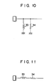
- Each of the resonance circuits 31 1 to 312 N -1 and 322 to 32 2N - 1 is comprised of a parallel resonance circuit which, as shown in Fig. 10, is formed of an inductor 33 and a resistor 34 connected in parallel thereto.
- each parallel resonance circuit when the inductor 33 is set to a small inductance value, the central frequency becomes high. Further, when the resistor 34 is set to a large resistance value, the frequency band widens. Accordingly, by suitably setting the respective values of the inductor 33 and resistor 34, there are obtained resonance characteristics similar to the filtering characteristics of the fixed band pass filters 141 to 14 2N - 1 shown in Figs. 1 and 7. Thus, in this third embodiment, the same effect as attainable in the first and second embodiments of Figs. 1 and 7 is obtained.
- the resonance circuit employed in this embodiment is not limited to the parallel resonance circuit but may be such a serial resonance circuit as shown in Fig. 11. Further, the resonance circuits may not have to be provided for each of the drive circuit and receiving circuit, but may be provided for either of them.
- the band pass filters and resonance circuits are used.
- the same effect as in using the band pass filters and resonance circuits is also obtained without using these filters and resonance circuits. That is, in the ultrasonic transducer, the piezoelectric element used therein has the nature that its frequency response depends upon its thickness while its central frequency is in inverse proportion to the thickness. Accordingly, by varying the thickness of the ultrasonic transducer elements 1 to 2N-1 as shown in Figs. 12 and 13, the ultrasonic transducer 11 produces echo signals having similar characteristics to those in case of using the band pass filters.
- annular piezoelectric elements E 2 to E n whose thicknesses become sequentially greater toward the outside, are concentrically disposed with a central piezoelectric element E 1 of the smallest thickness. These piezoelectric elements E 1 to E n are connected to the delay section 15 through the amplifier section 13.
- the central piezoelectric element E l transmits and receives a signal having the highest frequency while the outer piezoelectric elements E 2 to E n transmit and receive signals having sequentially lower frequencies. Accordingly, by selecting the echo signals from the piezoelectric elements E 1 to E n by the variable band pass filter 17, the beam diameter of the ultrasonic transducer 11 is varied from a small diameter to a larger.
- the piezoelectric elements N-1 to 1 and N+l to 2N-1 whose thicknesses become sequentially greater toward the ends are disposed on both sides of the central piezoelectric element N of the smallest thickness, respectively.
- These piezoelectric elements are connected to the variable band pass filter 17 through the amplifir section 13 1 delay section 15 and adder 16 in that order.
- the beam diameter of the ultrasonic transducer is also varied from a small diameter to a large as in the embodiment of Fig. 12.
- Fig. 14 shows the ultrasonic imaging apparatus of linear-scan system according to the sixth embodiment of the invention.
- the ultrasonic transducer elements E l to E m are respectively connected to m input terminals of an m-input/n-output switching circuit 35, the n output terminals of which are respectively connected to the band pass filters 141, 142, 14 3 , ..., 14 n through the preamplifiers 13 1 to 13 n .
- the band pass filters 14 1 to 14n as shown in embodiments of the Figs.
- the filtering characteristic so that they may have gran- dually narrower band widths and gradually lower central frequencies as they go toward the furthermost ends.
- the ultrasonic transducer elements El to E m are sequentially changed over by the switching circuit one by one in units of n elements, the electron beams emitted from the n-number of ultrasonic transducer elements are focussed and linear-scan the object of the living body. Further, during the one-rate period, i.e., the transmitting and receiving period for one scanning line, the beam diameter of the ultrasonic transducer is substantially varied.
- such as ultrasonic imaging apparatus of linear-scan system as in this embodiment also has the same effect as that obtainable by the ultrasonic imaging apparatus of sector-scan system mentioned in the preceding embodiments.
- the switching circuit 35 is employed, but, since the switching operation of this circuit 35 is carried out during the blank period at the time of shift from one transmitting & receiving operation to the next transmitting & receiving operation, the noises produced from the switching operation of the switching circuit 35 do not affect, for example, the echo signal at all.
- the echo signals received by the transducer elements are respectively converted by the same into echo signal components having different central frequencies and different frequency bands, and then are composed into a composite echo signal.
- this composite echo signal is filtered by the variable band pass filter in accordance with its variable filtering characteristic and the beam diameter of the ultrasonic transducer is thus substantially varied, 'the imaging operation has no such undesirable effect of switching noises as may occur in regard to the ultrasonic imaging apparatus of variable beam-diameter system using the switching means.
- a precise ultrasonic tomographic image is obtained.
Abstract
Description
- This invention relates to an ultrasonic imaging apparatus designed to emit ultrasonic beams onto an object and convert the echo waves from the object into echo signals and process those echo signals and then display a tomographic image of the object onto a display unit.
- In an ultrasonic imaging apparatus such as, for example, an ultrasonic diagnosis apparatus, the resolution of a tomographic image obtained therefrom, especially the resolution of a tomographic image with regard tc the depth direction of an object, is determined depending upon the diameter of the ultrasonic beam irradiated onto the object. The diameter of the ultrasonic beam depends upon the caliber or diameter of an ultrasonic transducer and the focal distance of the ultrasonic beam. The diameter of the ultrasonic transducer can be varied by varying the number of drived ones of electric-to-acoustic conversion elements constituting the ultrasonic transducer. Further, the focal distance of the ultrasonic beam can be varied by varying the length of delay time respectively given to drive signals driving the electric-to-acoustic conversion elements. Accordingly, in order to obtain high resolution with regard, widely, to the depth direction of the object, it is sufficient to vary the beam diameter of the ultrasonic transducer and the focal distance of the ultrasonic beam in accordance with the distance from the ultrasonic transducer to the object, i.e., an object portion inside a living body.
- Conventionally, where it is desired to vary the diameter of the ultrasonic transducer, this variation in transducer diameter was made by varying, by electric switching elements, the number of electric-to-acoustic conversion elements to be energized. Further, where it is desired to vary the focal distance of the ultrasonic beam, this variation was made by changing over the delay elements connected to the e·=ectric-to-acoustic conversion elements by means of electric switching elements. In this method of varying the diameter of the ultrasonic transducer and the focal distance of the ultrasonic beam by using electric switching elements, however, the circuit construction of the ultrasonic imaging apparatus becomes complicated and yet the noises produced at the switching time are mixed into a tomographic image, failing to obtain a precise tomographic image. Furthermore, such noises often cause the electric circuits of the ultrasonic imaging apparatus and the ultrasonic transducer to make erroneous operations.
- Accordingly, the object of the invention is to provide an ultrasonic imaging apparatus which can substantially vary the ultrasonic beam diameter and the focal distance of the ultrasonic beam without using any electric switching element.
- According to the invention, to the electric-to-acoustic transducer elements constituting an ultrasonic transducer are respectively connected band pass filters. The band pass filters have different central frequencies and different frequency bands and pass therethrough their corresponding central frequency and band signal components of the echo signals from the transducer elements. The signal components passed through the band pass filters are added to obtain a composite echo signal and supplied to a variable band pass filter. The variable band pass filter shifts the central frequency keeping the band-width to be fixed and passes therethrough only desired signal components of the composite echo signal. That is, the variable band pass filter selectively passes therethrough the echo signal components passed through the fixed band pass filters, thus to substantially vary the ultrasonic beam diameter.
- This invention can be more fully understood from the following detailed description when taken in conjunction with the accompanying drawings, in which:
- Fig. 1 is a schematic block circuit diagram of an ultrasonic imaging apparatus according to an embodiment of the invention;
- Fig. 2 is a characteristic curve diagram of the fixed band pass filters shown in Fig. 1;
- Fig. 3 is a characteristic curve diagram of the variable band pass filter shown in Fig. 1;
- Fig. 4 is a circuit diagram showing the variable band pass filter shown in Fig. 1;
- Fig. 5 is a filtering characteristic diagram for explaining the operation of the variable band pass filter of Fig. 4;
- Fig. 6 is a view showing a variable-diameter ultrasonic beam of the ultrasonic imaging apparatus shown in Fig. 1;
- Fig. 7 is a schematic block circuit diagram of the ultrasonic imaging apparatus according to another embodiment of the invention;
- Fig. 8 is a view showing the frequency characteristic of the variable band pass filter shown in Fig. 7;
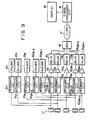
- Fig. 9 is a schematic block circuit diagram of the ultrasonic imaging apparatus according to a further embodiment of the invention, in which resonance circuits are respectively connected to the ultrasonic transducer elements;
- Fig. 10 is a view showing a parallel resonance circuit used in the third embodiment of Fig. 9;
- Fig. 11 is a view showing a serial resonance circuit used in the third embodiment of Fig. 9;
- Fig. 12 is a view showing the ultrasonic imaging apparatus according to a yet further embodiment of the invention, which uses a concentric type ultrasonic transducer comprised of transducer elements different in thickness;
- Fig. 13 is a view showing the ultrasonic imaging apparatus according to a yet further embodiment of the invention, which uses an ultrasonic transducer comprised of transducer strips different in thickness; and
- Fig. 14 is a circuit diagram showing the ultrasonic imaging apparatus of linear scan system according to a yet further embodiment of the invention.
- According to an embodiment shown in Fig. 1, electric-to-acoustic elements, i.e., ultrasonic transducer elements (e.g. piezoelectric elements) 1, 2, ..., N, ..., 2N-2, 2N-1 constituting an ultrasonic transducer 11 are respectively connected to the output terminals of
pulsers band pass filters 141 to 14N-1 and 14N+l to 142N-1 which are arranged on both sides of a central fixedband pass filter 14N corresponding to the central ultrasonic transducer element N, are respectively set, as they go away from thecentral filter 14N, to have sequentially lower central frequencies and sequentially narrower band widths. That is, when it is now assumed that the central fixedband pass filter 14N be so set as to have a curve BPN of Fig. 2, the side fixedband pass filters 141 to 14N-1 and 14N+1. to 142N-1 are so set as to have curves BPN-1 to BP1, respectively. - Output terminals of the fixed
band pass filters adder 16 throughdelay elements delay elements 151 to 152N-1 are so constructed as to have delay times corresponding to the transmission delay times set to converge or focus and sector-scan the ultrasonic beams. The output terminal of theadder 16 is connected to the input terminal of a variableband pass filter 17. This variable band pass filter is so constructed as to enable a shifting of the central frequency with a predetermined band width, as shown in Fig. 3. For example, thefilter 17 has a filtering characteristic which is indicated by curves VBPN, VBPN-1 . VBPN-2, ..., VBPl. A detailed circuit construction of the variableband pass filter 17 will be described later. The output terminal of the variableband pass filter 17 is connected to the input terminal of asignal processing circuit 18 for processing echo signals in accordance with an ordinary method. The output terminal of thissignal processing circuit 18 is connected to the input terminal of adisplay 19. - The variable
band pass filter 17 is comprised of ahigh pass filter 21 and alow pass filter 22, as shown in Fig. 4. Thehigh pass filter 21 is comprised of serially connected capacitor 21a and impedance element, e.g., FET 21b. The output terminal of FET 21b is connected to a power source Vcc through aresistor 23 and also to the emitter of atransistor 24, the base of which is grounded through aresistor 25. The collector of thetransistor 24 is grounded passing in parallel through a capacitor 22a and FET 22b of thelow pass filter 22, and is also connected to anoutput terminal 17b. The collector of thetransistor 24 is connected to a power source Vcc through aresistor 25. Control signal input terminals 28 and 29 are connected to the gates ofFETs amplifiers FETs high pass filter 21 andlow pass filter 22 vary. As a result, as shown in Fig. 5, a band pass region BP, i.e. an overlap region of a high pass region HP and a low pass region LP, is shifted. Thus, a signal corresponding to the band pass region BP is obtained from theoutput terminal 17b. - Next, the operation of the ultrasonic imaging apparatus according to the invention will be explained in accordance with the above-mentioned circuit construction. When the drive pulses from the
pulsers 121 to 122N-1 are supplied to theultrasonic transducer elements 1 to 2N-1 substantially at the same time, ultrasonic beams are emitted from theultrasonic transducer elements 1 to 2N-1 to an object, e.g. a living body (not shown). The echo waves reflected from the living body are converted into echo signals by theultrasonic transducer elements 1 to 2N-l. These echo signals are amplified by theamplifiers 131 to 132N-1 and then are supplied to the fixed band pass filters 141 to 142N-1, respectively. The echo signal has a limited band-width of spectrum components. The echo signals are respectively supplied to thedelay elements 151 to 152N-1 in regard to their components corresponding to the frequency bands set to theband pass filters 141 to 142N-1. That is to say, the central band pass filter 14N supplies the echo signal to thedelay element 15N in regard to its entire band-width components, while the band pass filters 141 and 142N-1 corresponding to thetransducer elements delay elements 151 and 152N-1 in regard to their narrowest band-width components, respectively. Thedelay elements 151 and 152N-1 delay the echo signal components supplied thereto in response to the drive pulses and supply their output echo signal components to theadder 16. Theadder 16 adds up those echo signal components to provide a composite echo signal, which is supplied to the variableband pass filter 17. Since as mentioned above the variableband pass filter 17 shifts the central frequency with a predetermined band width as shown in Fig. 3, from thefilter 17 there are outputted the echo signals which are displaced by degrees in respect of their central frequencies. That is to say, when thefilter 17 has a band pass characteristic VBPN of Fig. 3, the echo signal high-band components passed through the central fixed band pass filter 14N and the filters 14N-1 and 14N+l positioned next thereto pass through thefilter 17. This echo signal high band component is regarded as being substantially an echo signal from the central ultrasonic transducer element N, and corresponds to an echo signal when the ultrasonic transducer 11 is of a minimum beam diameter, namely corresponds to an echo signal obtained by the emission of an ultrasonic minimum-diameter beam BMl of Fig. 6. Where the ultrasonic beam is emitted into the living body, the smaller the beam diameter is, the more the resolution of the resulting tomographic image increases. However, an ultrasonic small-diameter beam fails to deeply enter the living body maintaining its diameter to be constant. Such beam is diffused in the non-deep interior zone of the living body, so that the resolution of a tomographic image from the deep interior zone of the living body decreases very much. In contrast, an ultrasonic large- diameter beam deeply enters the living body keeping its diameter to be constant, and as a result enables a tomographic image to be detected from the deep interior zone of the living body. Thus, varying the beam diameter in accordance with the depth of an object portion in the living body the tomographic image having a considerably high resolution is obtained with regard also to a deep interior zone of the living body. Conventionally, the change-over of the beam diameter was carried out by the use of electronic switches. In the present invention, however, the change-over of the beam diameter is carried out by shifting the band pass characteristic of the variableband pass filter 17 from the high to the low frequency band. That is, in the present invention, the ultrasonic beam diameter is changed over, by the Fig. 3-shown variation in the band pass characteristic, so that it may increase as in BDl, BD2, ..., BDn of Fig. 6 as the object portion deepens. Further, in the present invention, as the ultrasonic transducer elements go from the central N toward the furthermost-endultrasonic transducer element display 19 when the filtered echo signal outputted from the variableband pass filter 17 is processed by thesignal processing circuit 18 and then supplied to thedisplay 19. - In the above-mentioned embodiment, the fixed band pass filters and variable band pass filter are employed. In the present invention, however, a band pass type amplifier may be employed instead. In this case, the band pass type amplifier can be designed to have the function to coordinate the difference in sensitivity of the ultrasonic transducer elements as well as the function to amend the propagation attenuation of the ultrasonic beam. The transducer elements may be arranged not only linearly but also in the curved form. Further, the fixed band pass amplifiers may be provided at the immediately preceding stage to the preamplifiers.
- Next, the ultrasonic imaging apparatus according to another embodiment of the invention will be described with reference to Fig. 7., In this embodiment, the focal distahce as well as the beam diameter is varied. From the
pulser 12 drive pulses are generated with such time delays as to permit the ultrasonic beams to be focussed onto focal points Fl, ... FN-l, FN. To explain by using as a reference the drive pulse P0 supplied to the transducer element N, a drive pulse Pl generated earlier than the drive pulse P0 so as to permit the corresponding ultrasonic beam to be focussed onto the focal point F1 is supplied to the transducer elements N-l and N+l. Similarly, to thetransducer elements transducer elements 1 to 2N-1 and are thereby converted into echo signals. These echo signals are respectively supplied to the band pass filters 141 to 142N-1 via thepreamplifiers 131 to 132N-1. Thus, they are respectively filtered in accordance with their corresponding frequency bands. The filtered echo signals from the band pass filters 141 to 142N-1 are respectively supplied to thedelay elements 151 to 15N-1. These delay elements are respectively set with delay times for coordinating the mutual time differences between the drive pulses P0 to PN, into a desired one point of time. The echo signals, after passing through thedelay elements 151 to 15N-1, are added up or composed by theadder 16. The composite echo signal from theadder 16, when it is supplied to the variableband pass filter 17A, is filtered in accordance with the filtering characteristic, or such a varying filtering characteristic as shown in Fig. 8. That is, the variableband pass filter 17A has the filtering characteristic that the frequency band varies with the variation of its central frequency, and the above composite echo signal is filtered in accordance with the filtering characteristic VBPN, VBPN-1, VBPN-2, ..., VBP1 shown in Fig. 8. When'the composite echo signal is filtered in accordance with the Fig. 8-indicated filtering characteristics, with regard to the filtering in accordance with the characteristic VBPN there is obtained an echo signal component corresponding to the central transducer element N. Further, with regard to the filtering in accordance with the characteristic VBPN-1 there is obtained an echo signal component corresponding to the focal point Fl. In this case, the beam diameter of the ultrasonic transducer 11 is a coordinated beam diameter of the transducer elements N, N-l and N+l. When the above composite echo signal is filtered in accordacne with the characteristic VBPN-1, the echo signal component is obtained which corresponds to the axial focussing of the focal points Fl and F2. At this time, the beam diameter of the ultrasonic transducer 11 is a coordinated beam diameter of the transducer elements N, N-l, N+l, N-2, and N+2. In this way, according to this embodiment, both the beam diameter and the focal point can be varied. - In the above-mentioned two embodiments, the filtering characteristic of the variable band pass filter is continuously varied and the variable beam diameter and/or variable focal point is thus obtained without the use of any switching element. This means that no problem arise in regard to the switching noises. Further, since the beam diameter and/or focal point is continuously varied, the tomographic image obtained has continuity and thus becomes-good for observation.
- In the third embodiment of Fig. 9, drive
resonance circuits 311 to 3121s-1 and receiving resonance circuits 321 to 322N-1 are provided for the drive circuit including thepulsers 121 to 122N-1 and receiving circuit, respectively. Thedrive resonance circuits 311 to 312N-1, and receivingresonance circuits 321 to 322N-1, are respectively connected to theultrasonic transducer elements 1 to 2N-1. Each of the resonance circuits 311 to 312N-1 and 322 to 322N-1 is comprised of a parallel resonance circuit which, as shown in Fig. 10, is formed of aninductor 33 and aresistor 34 connected in parallel thereto. In each parallel resonance circuit, when theinductor 33 is set to a small inductance value, the central frequency becomes high. Further, when theresistor 34 is set to a large resistance value, the frequency band widens. Accordingly, by suitably setting the respective values of theinductor 33 andresistor 34, there are obtained resonance characteristics similar to the filtering characteristics of the fixed band pass filters 141 to 142N-1 shown in Figs. 1 and 7. Thus, in this third embodiment, the same effect as attainable in the first and second embodiments of Figs. 1 and 7 is obtained. Note here that the resonance circuit employed in this embodiment is not limited to the parallel resonance circuit but may be such a serial resonance circuit as shown in Fig. 11. Further, the resonance circuits may not have to be provided for each of the drive circuit and receiving circuit, but may be provided for either of them. - In the embodiments of Figs. 1, 7 and 9, the band pass filters and resonance circuits are used. However, by modifying the ultrasonic transducer in regard to the element thickness the same effect as in using the band pass filters and resonance circuits is also obtained without using these filters and resonance circuits. That is, in the ultrasonic transducer, the piezoelectric element used therein has the nature that its frequency response depends upon its thickness while its central frequency is in inverse proportion to the thickness. Accordingly, by varying the thickness of the
ultrasonic transducer elements 1 to 2N-1 as shown in Figs. 12 and 13, the ultrasonic transducer 11 produces echo signals having similar characteristics to those in case of using the band pass filters. - In the ultrasonic transducer shown in Fig. 12, annular piezoelectric elements E2 to En, whose thicknesses become sequentially greater toward the outside, are concentrically disposed with a central piezoelectric element E1 of the smallest thickness. These piezoelectric elements E1 to En are connected to the
delay section 15 through theamplifier section 13. In this fourth embodiment, the central piezoelectric element El transmits and receives a signal having the highest frequency while the outer piezoelectric elements E2 to En transmit and receive signals having sequentially lower frequencies. Accordingly, by selecting the echo signals from the piezoelectric elements E1 to En by the variableband pass filter 17, the beam diameter of the ultrasonic transducer 11 is varied from a small diameter to a larger. - In the fifth embodiment of Fig. 13, the piezoelectric elements N-1 to 1 and N+l to 2N-1 whose thicknesses become sequentially greater toward the ends are disposed on both sides of the central piezoelectric element N of the smallest thickness, respectively. These piezoelectric elements are connected to the variable
band pass filter 17 through theamplifir section 131delay section 15 andadder 16 in that order. In this embodiment, the beam diameter of the ultrasonic transducer is also varied from a small diameter to a large as in the embodiment of Fig. 12. - All of the foregoing embodiments are based on the sector-scan system, but this invention is also applicable to the ultrasonic imaging apparatus of linear-scan system. Fig. 14 shows the ultrasonic imaging apparatus of linear-scan system according to the sixth embodiment of the invention. In this embodiment, the ultrasonic transducer elements El to Em are respectively connected to m input terminals of an m-input/n-
output switching circuit 35, the n output terminals of which are respectively connected to the band pass filters 141, 142, 143, ..., 14n through thepreamplifiers 131 to 13n. The band pass filters 141 to 14n, as shown in embodiments of the Figs. 1, 7 and 9, are respectively set with the filtering characteristic so that they may have gran- dually narrower band widths and gradually lower central frequencies as they go toward the furthermost ends. In this embodiment, when the ultrasonic transducer elements El to Em are sequentially changed over by the switching circuit one by one in units of n elements, the electron beams emitted from the n-number of ultrasonic transducer elements are focussed and linear-scan the object of the living body. Further, during the one-rate period, i.e., the transmitting and receiving period for one scanning line, the beam diameter of the ultrasonic transducer is substantially varied. Accordingly, such as ultrasonic imaging apparatus of linear-scan system as in this embodiment also has the same effect as that obtainable by the ultrasonic imaging apparatus of sector-scan system mentioned in the preceding embodiments. In this embodiment, the switchingcircuit 35 is employed, but, since the switching operation of thiscircuit 35 is carried out during the blank period at the time of shift from one transmitting & receiving operation to the next transmitting & receiving operation, the noises produced from the switching operation of the switchingcircuit 35 do not affect, for example, the echo signal at all. - As above described, according to the invention, as the transducer elements of the ultrasonic transducer go from the central toward the furthermost elements, the echo signals received by the transducer elements are respectively converted by the same into echo signal components having different central frequencies and different frequency bands, and then are composed into a composite echo signal. And since this composite echo signal is filtered by the variable band pass filter in accordance with its variable filtering characteristic and the beam diameter of the ultrasonic transducer is thus substantially varied, 'the imaging operation has no such undesirable effect of switching noises as may occur in regard to the ultrasonic imaging apparatus of variable beam-diameter system using the switching means. Thus, according to the invention, a precise ultrasonic tomographic image is obtained.
Claims (13)
Priority Applications (1)
| Application Number | Priority Date | Filing Date | Title |
|---|---|---|---|
| DE8484113496T DE3279541D1 (en) | 1981-06-08 | 1982-06-07 | Ultrasonic imaging apparatus |
Applications Claiming Priority (2)
| Application Number | Priority Date | Filing Date | Title |
|---|---|---|---|
| JP86902/81 | 1981-06-08 | ||
| JP56086902A JPS57203434A (en) | 1981-06-08 | 1981-06-08 | Ultrasonic diagnostic apparatus |
Related Child Applications (1)
| Application Number | Title | Priority Date | Filing Date |
|---|---|---|---|
| EP84113496.8 Division-Into | 1982-06-07 |
Publications (2)
| Publication Number | Publication Date |
|---|---|
| EP0066876A1 true EP0066876A1 (en) | 1982-12-15 |
| EP0066876B1 EP0066876B1 (en) | 1985-10-30 |
Family
ID=13899759
Family Applications (2)
| Application Number | Title | Priority Date | Filing Date |
|---|---|---|---|
| EP84113496A Expired EP0140392B1 (en) | 1981-06-08 | 1982-06-07 | Ultrasonic imaging apparatus |
| EP82104980A Expired EP0066876B1 (en) | 1981-06-08 | 1982-06-07 | Ultrasonic imaging apparatus |
Family Applications Before (1)
| Application Number | Title | Priority Date | Filing Date |
|---|---|---|---|
| EP84113496A Expired EP0140392B1 (en) | 1981-06-08 | 1982-06-07 | Ultrasonic imaging apparatus |
Country Status (7)
| Country | Link |
|---|---|
| US (1) | US4437348A (en) |
| EP (2) | EP0140392B1 (en) |
| JP (1) | JPS57203434A (en) |
| KR (1) | KR860000380B1 (en) |
| AU (1) | AU542690B2 (en) |
| BR (1) | BR8203338A (en) |
| DE (2) | DE3267134D1 (en) |
Cited By (5)
| Publication number | Priority date | Publication date | Assignee | Title |
|---|---|---|---|---|
| EP0107172A2 (en) * | 1982-10-27 | 1984-05-02 | General Electric Company | Ultrasound imaging system employing operator controlled filter for reflected signal attenuation compensation |
| DE3311040A1 (en) * | 1983-03-25 | 1984-09-27 | Siemens AG, 1000 Berlin und 8000 München | Ultrasonic transmitting/receiving system |
| EP0263314A2 (en) * | 1986-10-06 | 1988-04-13 | Fried. Krupp Gesellschaft mit beschränkter Haftung | Transducer arrangement |
| EP0326623A1 (en) * | 1988-01-30 | 1989-08-09 | Mayser GmbH & Co. | Procedure for detecting the position of an obstacle |
| US6034922A (en) * | 1988-09-01 | 2000-03-07 | Schering Aktiengesellschaft | Ultrasonic processes and circuits for performing them |
Families Citing this family (33)
| Publication number | Priority date | Publication date | Assignee | Title |
|---|---|---|---|---|
| JPS57209041A (en) * | 1981-06-17 | 1982-12-22 | Yokogawa Electric Works Ltd | Ultrasonic diagnostic apparatus |
| US5488952A (en) * | 1982-02-24 | 1996-02-06 | Schoolman Scientific Corp. | Stereoscopically display three dimensional ultrasound imaging |
| JPS5962040A (en) * | 1982-09-29 | 1984-04-09 | 横河電機株式会社 | Ultrasonic probe |
| JPS59141937A (en) * | 1983-02-02 | 1984-08-14 | 横河電機株式会社 | Reflected wave receiving apparatus |
| JPS59127613U (en) * | 1983-02-18 | 1984-08-28 | 横河メディカルシステム株式会社 | Ultrasound diagnostic equipment |
| JPS59168845A (en) * | 1983-03-16 | 1984-09-22 | 横河メディカルシステム株式会社 | Ultrasonic transmitting and receiving system in ultrasonic imaging apparatus |
| JPS60114244A (en) * | 1983-11-28 | 1985-06-20 | 松下電器産業株式会社 | Ultrasonic diagnostic apparatus |
| JPS60164248A (en) * | 1984-02-06 | 1985-08-27 | Toshiba Corp | Ultrasonic wave diagnostic apparatus |
| US4608868A (en) * | 1985-03-22 | 1986-09-02 | Sri International | Ultrasonic reflex transmission imaging method and apparatus |
| US4730495A (en) * | 1985-03-22 | 1988-03-15 | Sri International | Ultrasonic reflex transmission imaging method and apparatus |
| US4763661A (en) * | 1986-02-11 | 1988-08-16 | Stanford University | Filtered ultrasonic wave method and apparatus for detecting diseased tissue |
| JPH01153146A (en) * | 1987-12-11 | 1989-06-15 | Yokogawa Medical Syst Ltd | Ultrasonic diagnostic apparatus |
| JPH01195844A (en) * | 1988-01-29 | 1989-08-07 | Yokogawa Medical Syst Ltd | Ultrasonic wave receiving phasing circuit |
| US5280724A (en) * | 1989-06-22 | 1994-01-25 | Nissan Motor Co., Ltd. | Ultrasonic inspection method for detecting defects in solid objects |
| JP2530237Y2 (en) * | 1990-08-14 | 1997-03-26 | ジーイー横河メディカルシステム株式会社 | Ultrasound imaging device |
| DE69208141T2 (en) * | 1991-04-15 | 1996-07-18 | Toshiba Kawasaki Kk | Device for destroying concretions |
| GB9116433D0 (en) * | 1991-07-30 | 1991-09-11 | Active Noise & Vibration Tech | Noise reduction system |
| US5301674A (en) * | 1992-03-27 | 1994-04-12 | Diasonics, Inc. | Method and apparatus for focusing transmission and reception of ultrasonic beams |
| US5438998A (en) * | 1993-09-07 | 1995-08-08 | Acuson Corporation | Broadband phased array transducer design with frequency controlled two dimension capability and methods for manufacture thereof |
| US5415175A (en) * | 1993-09-07 | 1995-05-16 | Acuson Corporation | Broadband phased array transducer design with frequency controlled two dimension capability and methods for manufacture thereof |
| US5743855A (en) * | 1995-03-03 | 1998-04-28 | Acuson Corporation | Broadband phased array transducer design with frequency controlled two dimension capability and methods for manufacture thereof |
| US5501222A (en) * | 1994-05-13 | 1996-03-26 | Briggs; Keith A. | System for imaging a region |
| JP3462351B2 (en) * | 1996-08-30 | 2003-11-05 | テルモ株式会社 | Ultrasound diagnostic equipment |
| JP3892104B2 (en) * | 1997-04-22 | 2007-03-14 | 株式会社日立メディコ | Ultrasonic diagnostic equipment |
| JP4551524B2 (en) * | 2000-03-06 | 2010-09-29 | 株式会社東芝 | Ultrasonic probe and ultrasonic diagnostic apparatus |
| JP4860059B2 (en) * | 2001-06-19 | 2012-01-25 | ジーイー・メディカル・システムズ・グローバル・テクノロジー・カンパニー・エルエルシー | Ultrasonic transmission / reception method and apparatus and ultrasonic imaging apparatus |
| ITSV20010030A1 (en) * | 2001-08-14 | 2003-02-14 | Esaote Spa | METHOD AND DEVICE FOR THE TRANSMISSION OF ULTRASONIC PULSES AND THE RECEPTION OF THE ECHO SIGNALS TO A HARMONIC OF THE TRANSMISSION FREQUENCY |
| US20070034011A1 (en) * | 2005-07-25 | 2007-02-15 | Pai-Chi Li | Method and apparatus for dynamic focusing in ultrasonic imaging |
| DE202007017913U1 (en) * | 2007-12-21 | 2008-03-06 | Fritsch, Thomas, Dr. | Multi-frequency transmit and receive unit for media-bound waves |
| DE202007017911U1 (en) * | 2007-12-21 | 2008-03-06 | Fritsch, Thomas, Dr. | Device for investigating the properties of a medium |
| US8770029B2 (en) * | 2011-10-04 | 2014-07-08 | General Electric Company | Method and apparatus for ultrasonic testing |
| JP5702326B2 (en) * | 2012-03-30 | 2015-04-15 | 富士フイルム株式会社 | Ultrasonic probe and ultrasonic diagnostic apparatus including the same |
| KR200487707Y1 (en) | 2018-06-27 | 2018-10-23 | 이경진 | Landing net type fishing tool with improved portability and usability |
Citations (11)
| Publication number | Priority date | Publication date | Assignee | Title |
|---|---|---|---|---|
| US3277451A (en) * | 1963-11-21 | 1966-10-04 | Edwin J Parssinen | Wide angle broad band hydrophone array |
| US3457543A (en) * | 1968-02-26 | 1969-07-22 | Honeywell Inc | Transducer for producing two coaxial beam patterns of different frequencies |
| US3833825A (en) * | 1973-04-11 | 1974-09-03 | Honeywell Inc | Wide-band electroacoustic transducer |
| US4016750A (en) * | 1975-11-06 | 1977-04-12 | Stanford Research Institute | Ultrasonic imaging method and apparatus |
| US4138895A (en) * | 1977-10-20 | 1979-02-13 | Rca Corporation | Switchable depth of focus pulse-echo ultrasonic-imaging display system |
| US4145931A (en) * | 1978-01-03 | 1979-03-27 | Raytheon Company | Fresnel focussed imaging system |
| GB2011075A (en) * | 1977-12-27 | 1979-07-04 | Gen Electric | Ultrasonic imaging systems |
| GB2016143A (en) * | 1978-03-09 | 1979-09-19 | Gen Electric | Sector scan ultrasonic imaging system |
| US4168628A (en) * | 1977-10-20 | 1979-09-25 | Rca Corporation | Pulse-echo ultrasonic-imaging display system having time-varied effective aperture |
| WO1980001537A1 (en) * | 1979-02-03 | 1980-08-07 | Fujitsu Ltd | Ultrasonic diagnostic equipment |
| US4228804A (en) * | 1978-02-28 | 1980-10-21 | Case Western Reserve University | Diagnostic ultrasonography utilizing frequency spectrum analysis presented in terms of B-scan color patterns or X-Y graph displays |
Family Cites Families (1)
| Publication number | Priority date | Publication date | Assignee | Title |
|---|---|---|---|---|
| US4016751A (en) * | 1973-09-13 | 1977-04-12 | The Commonwealth Of Australia Care Of The Department Of Health | Ultrasonic beam forming technique |
-
1981
- 1981-06-08 JP JP56086902A patent/JPS57203434A/en active Granted
-
1982
- 1982-06-01 AU AU84354/82A patent/AU542690B2/en not_active Ceased
- 1982-06-07 US US06/386,081 patent/US4437348A/en not_active Expired - Fee Related
- 1982-06-07 BR BR8203338A patent/BR8203338A/en unknown
- 1982-06-07 KR KR8202537A patent/KR860000380B1/en active
- 1982-06-07 EP EP84113496A patent/EP0140392B1/en not_active Expired
- 1982-06-07 DE DE8282104980T patent/DE3267134D1/en not_active Expired
- 1982-06-07 EP EP82104980A patent/EP0066876B1/en not_active Expired
- 1982-06-07 DE DE8484113496T patent/DE3279541D1/en not_active Expired
Patent Citations (12)
| Publication number | Priority date | Publication date | Assignee | Title |
|---|---|---|---|---|
| US3277451A (en) * | 1963-11-21 | 1966-10-04 | Edwin J Parssinen | Wide angle broad band hydrophone array |
| US3457543A (en) * | 1968-02-26 | 1969-07-22 | Honeywell Inc | Transducer for producing two coaxial beam patterns of different frequencies |
| US3833825A (en) * | 1973-04-11 | 1974-09-03 | Honeywell Inc | Wide-band electroacoustic transducer |
| US4016750A (en) * | 1975-11-06 | 1977-04-12 | Stanford Research Institute | Ultrasonic imaging method and apparatus |
| US4016750B1 (en) * | 1975-11-06 | 1994-04-05 | Stanford Research Inst | Ultrasonic imaging method and apparatus |
| US4138895A (en) * | 1977-10-20 | 1979-02-13 | Rca Corporation | Switchable depth of focus pulse-echo ultrasonic-imaging display system |
| US4168628A (en) * | 1977-10-20 | 1979-09-25 | Rca Corporation | Pulse-echo ultrasonic-imaging display system having time-varied effective aperture |
| GB2011075A (en) * | 1977-12-27 | 1979-07-04 | Gen Electric | Ultrasonic imaging systems |
| US4145931A (en) * | 1978-01-03 | 1979-03-27 | Raytheon Company | Fresnel focussed imaging system |
| US4228804A (en) * | 1978-02-28 | 1980-10-21 | Case Western Reserve University | Diagnostic ultrasonography utilizing frequency spectrum analysis presented in terms of B-scan color patterns or X-Y graph displays |
| GB2016143A (en) * | 1978-03-09 | 1979-09-19 | Gen Electric | Sector scan ultrasonic imaging system |
| WO1980001537A1 (en) * | 1979-02-03 | 1980-08-07 | Fujitsu Ltd | Ultrasonic diagnostic equipment |
Cited By (9)
| Publication number | Priority date | Publication date | Assignee | Title |
|---|---|---|---|---|
| EP0107172A2 (en) * | 1982-10-27 | 1984-05-02 | General Electric Company | Ultrasound imaging system employing operator controlled filter for reflected signal attenuation compensation |
| EP0107172A3 (en) * | 1982-10-27 | 1985-08-28 | General Electric Company | Ultrasound imaging system employing operator controlled filter for reflected signal attenuation compensation |
| DE3311040A1 (en) * | 1983-03-25 | 1984-09-27 | Siemens AG, 1000 Berlin und 8000 München | Ultrasonic transmitting/receiving system |
| EP0263314A2 (en) * | 1986-10-06 | 1988-04-13 | Fried. Krupp Gesellschaft mit beschränkter Haftung | Transducer arrangement |
| EP0263314A3 (en) * | 1986-10-06 | 1988-07-27 | Fried. Krupp Gesellschaft Mit Beschrankter Haftung | Transducer arrangement |
| EP0326623A1 (en) * | 1988-01-30 | 1989-08-09 | Mayser GmbH & Co. | Procedure for detecting the position of an obstacle |
| US6034922A (en) * | 1988-09-01 | 2000-03-07 | Schering Aktiengesellschaft | Ultrasonic processes and circuits for performing them |
| US6221017B1 (en) | 1988-09-01 | 2001-04-24 | Schering Aktiengesellschaft | Ultrasonic processes and circuits for performing them |
| US6443899B2 (en) | 1988-09-01 | 2002-09-03 | Schering Aktiengesellschaft | Ultrasonic processes and circuits for performing them |
Also Published As
| Publication number | Publication date |
|---|---|
| AU542690B2 (en) | 1985-03-07 |
| AU8435482A (en) | 1983-01-06 |
| BR8203338A (en) | 1983-05-24 |
| JPS57203434A (en) | 1982-12-13 |
| EP0140392B1 (en) | 1989-03-15 |
| EP0066876B1 (en) | 1985-10-30 |
| JPH0360491B2 (en) | 1991-09-13 |
| EP0140392A3 (en) | 1985-07-17 |
| US4437348A (en) | 1984-03-20 |
| KR860000380B1 (en) | 1986-04-16 |
| EP0140392A2 (en) | 1985-05-08 |
| DE3267134D1 (en) | 1985-12-05 |
| DE3279541D1 (en) | 1989-04-20 |
| KR840000219A (en) | 1984-02-18 |
Similar Documents
| Publication | Publication Date | Title |
|---|---|---|
| US4437348A (en) | Ultrasonic imaging apparatus | |
| EP0072498B1 (en) | Ultrasonic imaging apparatus | |
| US4305296A (en) | Ultrasonic imaging method and apparatus with electronic beam focusing and scanning | |
| US4442713A (en) | Frequency varied ultrasonic imaging array | |
| JP3352098B2 (en) | Object inspection system by ultrasonic echograph | |
| US4413520A (en) | Ultrasonic imaging apparatus | |
| DE3211719C2 (en) | Ultrasonic echo examination device | |
| US5511423A (en) | Ultrasonic diagnostic apparatuses and methods therefor | |
| US6716173B2 (en) | Ultrasonic imaging method and ultrasonic imaging apparatus | |
| US4552020A (en) | Apparatus for the scanning of objects by means of ultrasound echography | |
| US4603586A (en) | Delay line circuit arrangement and ultrasonic imaging apparatus utilizing the same | |
| JP4325981B2 (en) | Harmonic transducer element structure and characteristics | |
| EP0116979B1 (en) | Ultrasonic diagnostic apparatus | |
| US4837754A (en) | Ultrasonic wave phase matching apparatus | |
| US4375166A (en) | Ultrasound examination apparatus comprising a mosaic of transducers of an electrostrictive material | |
| JPH06114056A (en) | Ultrasonic diagnostic apparatus | |
| JPH0119549B2 (en) | ||
| JPH0614927A (en) | Ultrasonic diagnostic device | |
| JP2970022B2 (en) | Receiving phasing circuit of ultrasonic equipment | |
| JP3515630B2 (en) | Ultrasound diagnostic equipment | |
| JP3216372B2 (en) | Ultrasound diagnostic equipment | |
| JPS6148344A (en) | Ultrasonic diagnostic apparatus | |
| JPS58216044A (en) | Ultrasonic diagnostic apparatus | |
| JPH02124152A (en) | Ultrasonic diagnosing device | |
| JPS63209630A (en) | Ultrasonic diagnostic apparatus |
Legal Events
| Date | Code | Title | Description |
|---|---|---|---|
| PUAI | Public reference made under article 153(3) epc to a published international application that has entered the european phase |
Free format text: ORIGINAL CODE: 0009012 |
|
| 17P | Request for examination filed |
Effective date: 19820705 |
|
| AK | Designated contracting states |
Designated state(s): DE FR GB NL |
|
| RAP1 | Party data changed (applicant data changed or rights of an application transferred) |
Owner name: KABUSHIKI KAISHA TOSHIBA |
|
| GRAA | (expected) grant |
Free format text: ORIGINAL CODE: 0009210 |
|
| AK | Designated contracting states |
Designated state(s): DE FR GB NL |
|
| REF | Corresponds to: |
Ref document number: 3267134 Country of ref document: DE Date of ref document: 19851205 |
|
| ET | Fr: translation filed | ||
| PLBE | No opposition filed within time limit |
Free format text: ORIGINAL CODE: 0009261 |
|
| STAA | Information on the status of an ep patent application or granted ep patent |
Free format text: STATUS: NO OPPOSITION FILED WITHIN TIME LIMIT |
|
| 26N | No opposition filed | ||
| REG | Reference to a national code |
Ref country code: GB Ref legal event code: 746 |
|
| PGFP | Annual fee paid to national office [announced via postgrant information from national office to epo] |
Ref country code: GB Payment date: 19890531 Year of fee payment: 8 |
|
| PGFP | Annual fee paid to national office [announced via postgrant information from national office to epo] |
Ref country code: FR Payment date: 19890613 Year of fee payment: 8 |
|
| PGFP | Annual fee paid to national office [announced via postgrant information from national office to epo] |
Ref country code: NL Payment date: 19890630 Year of fee payment: 8 |
|
| PGFP | Annual fee paid to national office [announced via postgrant information from national office to epo] |
Ref country code: DE Payment date: 19890831 Year of fee payment: 8 |
|
| PG25 | Lapsed in a contracting state [announced via postgrant information from national office to epo] |
Ref country code: GB Effective date: 19900607 |
|
| PG25 | Lapsed in a contracting state [announced via postgrant information from national office to epo] |
Ref country code: NL Effective date: 19910101 |
|
| GBPC | Gb: european patent ceased through non-payment of renewal fee | ||
| NLV4 | Nl: lapsed or anulled due to non-payment of the annual fee | ||
| PG25 | Lapsed in a contracting state [announced via postgrant information from national office to epo] |
Ref country code: FR Effective date: 19910228 |
|
| PG25 | Lapsed in a contracting state [announced via postgrant information from national office to epo] |
Ref country code: DE Effective date: 19910301 |
|
| REG | Reference to a national code |
Ref country code: FR Ref legal event code: ST |