EP0066743A1 - Measuring device for automatically determining velocity, distance travelled and changes of direction of a moving body - Google Patents
Measuring device for automatically determining velocity, distance travelled and changes of direction of a moving body Download PDFInfo
- Publication number
- EP0066743A1 EP0066743A1 EP82104355A EP82104355A EP0066743A1 EP 0066743 A1 EP0066743 A1 EP 0066743A1 EP 82104355 A EP82104355 A EP 82104355A EP 82104355 A EP82104355 A EP 82104355A EP 0066743 A1 EP0066743 A1 EP 0066743A1
- Authority
- EP
- European Patent Office
- Prior art keywords
- measuring
- measuring device
- vehicle
- doppler
- output
- Prior art date
- Legal status (The legal status is an assumption and is not a legal conclusion. Google has not performed a legal analysis and makes no representation as to the accuracy of the status listed.)
- Granted
Links
Images


Classifications
-
- G—PHYSICS
- G01—MEASURING; TESTING
- G01S—RADIO DIRECTION-FINDING; RADIO NAVIGATION; DETERMINING DISTANCE OR VELOCITY BY USE OF RADIO WAVES; LOCATING OR PRESENCE-DETECTING BY USE OF THE REFLECTION OR RERADIATION OF RADIO WAVES; ANALOGOUS ARRANGEMENTS USING OTHER WAVES
- G01S15/00—Systems using the reflection or reradiation of acoustic waves, e.g. sonar systems
- G01S15/02—Systems using the reflection or reradiation of acoustic waves, e.g. sonar systems using reflection of acoustic waves
- G01S15/50—Systems of measurement, based on relative movement of the target
- G01S15/58—Velocity or trajectory determination systems; Sense-of-movement determination systems
- G01S15/62—Sense-of-movement determination
-
- G—PHYSICS
- G01—MEASURING; TESTING
- G01S—RADIO DIRECTION-FINDING; RADIO NAVIGATION; DETERMINING DISTANCE OR VELOCITY BY USE OF RADIO WAVES; LOCATING OR PRESENCE-DETECTING BY USE OF THE REFLECTION OR RERADIATION OF RADIO WAVES; ANALOGOUS ARRANGEMENTS USING OTHER WAVES
- G01S15/00—Systems using the reflection or reradiation of acoustic waves, e.g. sonar systems
- G01S15/02—Systems using the reflection or reradiation of acoustic waves, e.g. sonar systems using reflection of acoustic waves
- G01S15/50—Systems of measurement, based on relative movement of the target
- G01S15/58—Velocity or trajectory determination systems; Sense-of-movement determination systems
- G01S15/60—Velocity or trajectory determination systems; Sense-of-movement determination systems wherein the transmitter and receiver are mounted on the moving object, e.g. for determining ground speed, drift angle, ground track
Definitions
- the invention relates to a measuring device for automatically measuring speed, distance covered and changes in direction of moving bodies with the aid of Doppler shifts measured by ultrasound.
- this is achieved in that two measuring devices are provided at a distance corresponding essentially to the vehicle width on the underside of a vehicle, which consist of a measuring part in and / or against the direction of travel consisting of transmitter and receiver, the transmitters being arranged in this way are that the ultrasound beams emitted at an angle ⁇ are reflected on the road and received by the receivers, and the occurring Doppler shift of the received signals, the speed and the distance traveled and the difference between the left and right path measurement values of the measuring devices compared to the directional deviation of the vehicle indicates the lane.
- information about the speed is obtained after transmission, reflection on the background and reception of an ultrasound signal.
- a mathematical integration over time gives the path covered. If the path on the left and right side of the vehicle is determined separately, the difference between the paths gives an indication of the change in angle of the longitudinal axis of the vehicle that occurred within the integration time.
- two measuring devices 3, 3a are provided according to the invention, each of which consists of a transmitter 1 and a receiver 2.
- the transmitter 1 emits its ultrasonic signal in and / or against the direction of travel at an angle ( ⁇ ).
- the signal reflected on uneven ground reaches receiver 2.
- the output signal of the receiver 2 is raised in a subsequent amplifier 8 regularly to such an extent that the signal level is sufficient to control a phase locked loop 9 (PLL).
- PLL phase locked loop 9
- the phase-locked loop 9 follows a change in the input signal so slowly that Doppler shifts in the input signal due to jerky movements of the vehicle 5 do not result in a significant change in the output frequency of the phase-locked loop 9.
- changes in the output frequency of the phase locked loop 9 due to changes in the speed of the vehicle after a few tenths of a second to the output signal.
- a demodulator 10 is connected to the output of the phase-locked loop 9, which subtracts the transmitter frequency from the Doppler frequency when measuring in the direction of travel, or subtracts the Doppler frequency from the transmitter frequency when measuring against the direction of travel and passes it on as a differential signal.
- This difference signal has a frequency which is in a mathematically exact relationship to the speed of the vehicle 5.
- the difference signal is fed to a digital counter 12 which, after a certain number of pulses, emits an output pulse at the moment of zero crossing, as a result of which information loss due to the occurrence of counting errors is avoided.
- This time interval is fed to a microcomputer 13.
- the measured value is converted from frequency to speed and frequency in time and distance.
- the microcomputer 13 determines the speed from the difference frequency and the transmitter frequency supplied as an input signal. A mathematical integration of the speed over time, ie by counting the difference frequency, results in the path that the vehicle 5 concerned has covered. Since the vehicle 5 predominantly moves on an uneven road 7, the angle of the reflected beam will fluctuate by an average.
- both the left and right measuring devices 3, 3a exist of a forward measuring part I and a backward measuring part II, one measuring part determining the transmitter frequency + differential frequency and the other measuring part determining the transmitter frequency - differential frequency.
- both measuring parts I and II are fastened on a common angular base plate 14, specifically on one leg directed forwards and backwards, respectively.
- the angular base plate 14 is fastened to a vehicle transverse axis, damper elements being provided which dampen any tilting movements that occur. Error corrections derived by comparing the measured values of the measuring parts I and II are supplied to the microcomputer 13. If the length of the measuring beam changes due to vertical suspension of the vehicle 5, then a brief error occurs within the measuring signal, which, however, drops back to zero when the springing back.
- two measuring devices 3, 3a are arranged at a predetermined distance from one another according to the invention.
- the path signals obtained at the same time result in a measured value for the directional deviation of the vehicle 5 along the path.
Abstract
Description
Die Erfindung betrifft eine Meßeinrichtung zum selbsttätigen Messen von Geschwindigkeit, zurückgelegtem Weg sowie Richtungsänderungen beweglicher Körper mit Hilfe von an Ultraschall gemessener Dopplerverschiebungen.The invention relates to a measuring device for automatically measuring speed, distance covered and changes in direction of moving bodies with the aid of Doppler shifts measured by ultrasound.
Bei landwirtschaftlichen Fahrzeugen ist das übliche Verfahren der Geschwindigkeits- und Wegmessung durch Messung der Radumdrehungen und Multiplikation mit dem Radumfang wegen des Schlupfs, der seitlichen Abweichungen durch Rutschen sowie durch einen differierenden Reifendruck so stark fehlerbehaftet, daß ein automatisches Führen derartiger Fahrzeuge nicht möglich erscheint.In the case of agricultural vehicles, the usual method of measuring speed and distance by measuring the wheel revolutions and multiplying by the wheel circumference is so prone to errors because of the slip, the lateral deviations due to slipping and due to a differing tire pressure that automatic driving of such vehicles does not appear to be possible.
Es sind somit bereits Systeme bekannt, bei welchen über von ortsfesten Sendern abgegebene Funkwellen, über ortsfeste Spiegel geleitete Lichtquellen oder im Acker untergebrachten Leiterschleifen eine Ortsbestimmung von landwirtschaftlichen Fahrzeugen durchgeführt wird. Daneben gibt es ein optisches System, welches aus der Korrelation zufallsverteilter Helligkeiten an einem Ausschnitt der Fahrbahn und deren zeitlicher Verschiebung eine Aussage über die Geschwindigkeit und den Weg des betreffenden Fahrzeuges erlaubt.Systems are thus already known in which the location of agricultural vehicles is determined by radio waves emitted by stationary transmitters, light sources guided by stationary mirrors or conductor loops housed in the fields leads. In addition, there is an optical system which, based on the correlation of randomly distributed brightnesses on a section of the road and its time shift, allows a statement to be made about the speed and the path of the vehicle in question.
Derartige Einrichtungen zum automatischen Führen von landwirtschaftlichen Fahrzeugen auf dem Acker haben jedoch den Nachteil, daß ein ackerfestes Bezugssystem erforderlich ist, was zu einem relativ hohen Aufwand führt.Devices of this type for automatically guiding agricultural vehicles on the field, however, have the disadvantage that a fixed reference system is required, which leads to a relatively high outlay.
Es ist somit die Aufgabe der vorliegenden Erfindung, eine Meßeinrichtung zu schaffen, welche bei Vermeidung eines ackerfesten Bezugssystems die genaue Ableitung bestimmter Meßgrößen zum automatischen Führen von landwirtschaftlichen Fahrzeugen erlaubt.It is therefore the object of the present invention to provide a measuring device which, while avoiding a field-fixed reference system, allows the precise derivation of certain measured variables for the automatic driving of agricultural vehicles.
Erfindungsgemäß wird dies dadurch erreicht, daß in einem im wesentlichen der Fahrzeugbreite entsprechenden Abstand an der Unterseite eines Fahrzeuges zwei Meßeinrichtungen vorgesehen sind, welche aus einem in und/oder gegen die Fahrtrichtung messenden, aus Sender und Empfänger bestehenden Meßteil bestehen, wobei die Sender derart angeordnet sind, daß die unter einem Winkei α ausgesendeten Ultraschallstrahlen an der Fahrbahn reflektiert und von den Empfängern empfangen werden, und wobei die auftretende Dopplerverschiebung der empfangenen Signale die Geschwindigkeit und den zurückgelegten Weg und die Differenz der linken und rechten Wegmeßwerte der Meßeinrichtungen die Richtungsabweichung des Fahrzeuges gegenüber der Fahrbahn angibt.According to the invention this is achieved in that two measuring devices are provided at a distance corresponding essentially to the vehicle width on the underside of a vehicle, which consist of a measuring part in and / or against the direction of travel consisting of transmitter and receiver, the transmitters being arranged in this way are that the ultrasound beams emitted at an angle α are reflected on the road and received by the receivers, and the occurring Doppler shift of the received signals, the speed and the distance traveled and the difference between the left and right path measurement values of the measuring devices compared to the directional deviation of the vehicle indicates the lane.
Im Rahmen der vorliegenden Erfindung wird nach Aussendung, Reflexion am Untergrund und Empfang eines Ultraschallsignals eine Information über die Geschwindigkeit gewonnen. Durch eine mathematische Integration über die Zeit erhält man den zurückgelegten Weg. Wird der Weg über die linke und rechte Seite des Fahrzeuges gesondert bestimmt, erhält man aus der Differenz der Wege eine Angabe über die innerhalb der Integrationszeit erfolgte Winkeländerung der Längsachse des Fahrzeuges.In the context of the present invention, information about the speed is obtained after transmission, reflection on the background and reception of an ultrasound signal. A mathematical integration over time gives the path covered. If the path on the left and right side of the vehicle is determined separately, the difference between the paths gives an indication of the change in angle of the longitudinal axis of the vehicle that occurred within the integration time.
Durch diese neue Meßeinrichtung können somit drei wesentliche erfindungsbestimmende Vorteile erreicht werden:
- a) Durch die Anordnung einer linken und rechten Meßeinrichtung wird eine Richtungsabweichung des Fahrzeuges längs eines Weges infolge eines Vergleiches der beiden gewonnenen Wegsignale durch eine Korrektur verhindert.
- b) Jede Meßeinrichtung besteht aus einem vorwärts und rückwärts messenden Meßteil, wodurch der Meßfehler infolge von Nickbewegungen des Fahrzeuges wesentlich auf Werte unter 0,1 % verkleinert wird. Der Einfluß von Radschlupf und Hysterese ist dabei bedeutungslos.
- c) Zur Lösung vorgenannter Aufgaben ist keine ortsfeste Anlage notwendig.
- a) The arrangement of a left and right measuring device prevents a directional deviation of the vehicle along a path due to a comparison of the two path signals obtained by a correction.
- b) Each measuring device consists of a forward and backward measuring part, whereby the measurement error due to pitching movements of the vehicle is significantly reduced to values below 0.1%. The influence of wheel slip and hysteresis is irrelevant.
- c) No fixed installation is required to solve the above-mentioned tasks.
Vorteilhafte weitere Ausgestaltungen der Erfindung sind in den Unteransprüchen gekennzeichnet.Advantageous further developments of the invention are characterized in the subclaims.
Die Erfindung soll nunmehr anhand eines in der Zeichnung dargestellten Ausführungsbeispieles näher erläutert werden. Es zeigen:
- Fig. 1 ein Fahrzeug mit einer Meßeinrichtung gemäß der Erfindung, bei welcher die Meßköpfe in und gegen die Fahrtrichtung senden und empfangen,
- Fig. 2 einen elektronischen Blockschaltplan der erfindungsgemäßen Meßeinrichtung von Fig. 1, und
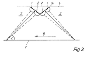
- Fig. 3 die schematische Ansicht der vorwärts und rückwärts gerichteten Meßteile gemäß der Erfindung.
- 1 shows a vehicle with a measuring device according to the invention, in which the measuring heads send and receive in and against the direction of travel,
- Fig. 2 is an electronic block diagram of the measuring device according to the invention of Fig. 1, and
- Fig. 3 is a schematic view of the forward and backward measuring parts according to the invention.
Entsprechend Fig. 1 sind gemäß der Erfindung zwei Meßeinrichtungen 3, 3a vorgesehen, welche aus je einem Sender 1 und einem Empfänger 2 bestehen. Der Sender 1 strahlt dabei unter einem Winkel (α ) sein UltraschallSignal in und/oder gegen die Fahrtrichtung ab. Das an Bodenunebenheiten reflektierte Signal gelangt in den Empfänger 2.1, two
Gemäß Fig. 2 wird das Ausgangssignal des Empfängers 2 in einem nachfolgenden Verstärker 8 regelmäßig so weit angehoben, daß die Signalhöhe ausreicht, um einen Phasenregelkreis 9 (PLL) anzusteuern. Der Phasenregelkreis 9 folgt einer Änderung des Eingangssignals so träge, daß Dopplerverschiebungen des Eingangssignals durch ruckartige Bewegungen des Fahrzeuges 5 keine wesentliche Änderung der Ausgangsfrequenz des Phasenregelkreises 9 zur Folge haben. Hingegen werden Änderungen der Ausgangsfrequenz des Phasenregelkreises 9 infolge von Geschwindigkeitsänderungen des Fahrzeuges nach einigen zehntel Sekunden auf das Ausgangssignal übertragen. Am Ausgang des Phasenregelkreises 9 ist ein Demodulator 10 angeschlossen, der bei Messung in Fahrtrichtung die Senderfrequenz von der Dopplerfrequenz subtrahiert, bzw. bei Messung gegen die Fahrtrichtung die Dopplerfrequenz von der Senderfrequenz subtrahiert und als Differenzsignal weiterleitet. Dieses Differenzsignal besitzt dabei eine Frequenz, welche in einem mathematisch exakten Zusammenhang zu der Geschwindigkeit des Fahrzeuges 5 steht.2, the output signal of the
Das Differenzsignal wird einem Digitalzähler 12 zugeführt, welcher nach einer bestimmten Anzahl von Impulsen im Augenblick des Nulldurchganges einen Ausgangsimpuls abgibt, wodurch ein Informationsverlust durch das Auftreten von Zählfehlern vermieden wird. Dieses Zeitintervall wird einem Mikrorechner 13 zugeführt. Innerhalb dieses Mikrorechners 13 erfolgt die Meßwertumwandlung von Frequenz in Geschwindigkeit sowie Frequenz in Zeit und Weg. Der Mikrorechner 13 bestimmt aus der Differenzfrequenz und der als Eingangssignal zugeführten Senderfrequenz die Geschwindigkeit. Durch eine mathematische Integration der Geschwindigkeit nach der Zeit, d. h. durch Zählung der Differenzfrequenz, ergibt sich der Weg, welchen das betreffende Fahrzeug 5 zurückgelegt hat. Da sich das Fahrzeug 5 überwiegend auf unebener Fahrbahn 7 bewegt, wird der Winkel des reflektierten Strahls um einen Mittelwert schwanken. Dies bedingt eine Längenänderung des Meßstrahles, was bei gleich großen Schwankungen um den Mittelwert zu einem Fehler in der Geschwindigkeits-und Wegbestimmung führt. Aus diesem Grunde besteht sowohl die linke als auch rechte Meßeinrichtung 3, 3a aus je einem vorwärtsmessenden Meßteil I und einem rückwärtsmessenden MeßteilII, wobei der eine Meßteil die Senderfrequenz + Differenzfrequenz und der andere Meßteil die Senderfrequenz - Differenzfrequenz bestimmt.The difference signal is fed to a
Gemäß Fig. 3 sind beide Meßteile I und II auf einer gemeinsamen winkelförmigen Grundplatte 14, und zwar auf jeweils einem nach vorn respektive nach hinten gerichteten Schenkel,befestigt. Durch Vorsehen einer Einrichtung, welche einen Vergleich der beiden Dopplersignale der vorwärts und rückwärts messenden Meßteile gestattet, kann im Rahmen der Erfindung der Meßfehler auf Werte wesentlich unter 0,1 % verringert werden. Die winkelförmige Grundplatte 14 ist dabei an einer Fahrzeugquerachse befestigt, wobei Dämpferelemente vorgesehen sind, welche auftretende Kippbewegungen bedämpfen. Durch den Vergleich der Meßwerte der Meßteile I und II abgeleitete Fehlerkorrekturen werden dem Mikrorechner 13 zugeführt. Ändert sich durch vertikales Durchfedern des Fahrzeuges 5 die Meßstrahllänge, so tritt innerhalb des Meßsignals ein kurzzeitiger Fehler auf, der jedoch beim Zurückfedern wieder auf Null absinkt.According to FIG. 3, both measuring parts I and II are fastened on a common
Um Richtungsabweichungen zu messen, sind gemäß der Erfindung zwei Meßeinrichtungen 3, 3a in einem vorgegebenen Abstand zueinander angeordnet. Die gleichzeitig gewonnenen Wegsignale ergeben dabei einen Meßwert für die Richtungsabweichung des Fahrzeuges 5 längs des Weges.In order to measure directional deviations, two
Claims (7)
dadurch gekennzeichnet,
daß in einem im wesentlichen der Fahrzeugbreite entsprechenden Abstand an der Unterseite (4) eines Fahrzeuges (5) zwei Meßeinrichtungen (3, 3a) vorgesehen sind, welche aus einem in und/oder gegen die Fahrtrichtung (6) messenden, aus Sender (1) und Empfänger (2) bestehenden Meßteil (I, II) bestehen, wobei die Sender (1) derart angeordnet sind, daß die unter einem Winkel (α ) ausgesendeten Ultraschallstrahlen an der Fahrbahn (7) reflektiert und von den Empfängern (2) empfangen werden, und wobei die auftretende Dopplerverschiebung der empfangenen Signale die Geschwindigkeit und den zurückgelegten Weg und die Differenz der linken und rechten Wegmeßwerte der Meßeinrichtungen (3, 3a) die Richtungsabweichung des Fahrzeuges (5) gegenüber der Fahrbahn (7) angibt.1. Measuring device for the automatic measurement of speed, distance covered and changes in direction of moving bodies with the aid of Doppler shifts measured on ultrasound,
characterized,
that two measuring devices (3, 3a) are provided at a distance corresponding essentially to the vehicle width on the underside (4) of a vehicle (5), which consists of a transmitter (1) measuring in and / or against the direction of travel (6) and receiver (2) existing measuring part ( I , II), the transmitters (1) being arranged such that the ultrasound beams emitted at an angle (α) are reflected on the roadway (7) and received by the receivers (2) , and wherein the occurring Doppler shift of the received signals indicates the speed and the distance covered and the difference between the left and right distance measurement values of the measuring devices (3, 3a) the directional deviation of the vehicle (5) from the roadway (7).
dadurch gekennzeichnet,
daß die Sender (1) und Empfänger (2) der beiden Meßeinrichtungen (3, 3a) sowohl in als auch gegen die Fahrtrichtung (6) ausgerichtet sind, und daß ein Vergleich der empfangenen Signale durchgeführt wird, welcher eine wesentliche Verkleinerung des auftretenden Meßfehlers erlaubt.2. Measuring device according to claim 1,
characterized,
that the transmitter (1) and receiver (2) of the two measuring devices (3, 3a) both in and against the Direction of travel (6) are aligned, and that a comparison of the received signals is carried out, which allows a substantial reduction in the measurement error occurring.
dadurch gekennzeichnet,
daß die von den Empfängern (2) abgegebenen Dopplersignale nach Verstärkung durch entsprechende Verstärker (8) Phasenregelkreisen (9) zur Regenerierung zugeführt sind, wobei letztere so bemessen sind, daß an den Empfängern (2) auftretende Signalausfälle für einen gegen die Zeitkonstante des Fahrzeuges (5) kleinen Zeitraum überbrückbar sind.3. Measuring device according to claim 1 or 2,
characterized,
that the Doppler signals emitted by the receivers (2), after amplification by appropriate amplifiers (8), are fed to phase-locked loops (9) for regeneration, the latter being dimensioned such that signal failures occurring at the receivers (2) for a signal against the time constant of the vehicle ( 5) small period can be bridged.
dadurch gekennzeichnet,
daß an den Ausgängen (9a) der beiden Phasenregelkreise (9) Demodulatoren (10) angeordnet sind, deren Ausgangsfrequenzen der Differenz von Senderfrequenz und Empfängerdopplerfrequenz entsprechen.4. Measuring device according to claim 3,
characterized,
that demodulators (10) are arranged at the outputs (9a) of the two phase-locked loops (9), the output frequencies of which correspond to the difference between the transmitter frequency and the receiver Doppler frequency.
dadurch gekennzeichnet,
daß die von den Phasenregelkreisen (10) abgegebenen Differenzsignale nach Durchlaufen entsprechender Impulsformer Digitalzählern (12) zugeführt sind, welche nach einer vorgegebenen Anzahl von Impulsen im Augenblick des Nulldurchganges jeweils einen Ausgangsimpuls abgeben.5. Measuring device according to claim 4,
characterized,
that the differential signals emitted by the phase-locked loops (10) are fed to digital counters (12) after passing through corresponding pulse shapers, which each output an output pulse after a predetermined number of pulses at the moment of zero crossing.
dadurch gekennzeichnet,
daß die Ausgangsimpulse der Digitalzähler (12) einem Mikrorechner (13) zugeführt sind, welcher unter Berücksichtigung des Zeitintervalls zwischen zwei Ausgangsimpulsen und vorgegebener Sollwertgrößen entsprechende Stellgrößen abgibt, die auf das Steuersystem des Fahrzeuges (5) zurückwirken.6. Measuring device according to claim 5,
characterized,
that the output pulses of the digital counters (12) are fed to a microcomputer (13) which, taking into account the time interval between two output pulses and predetermined setpoint variables, emits corresponding manipulated variables which have an effect on the control system of the vehicle (5).
dadurch gekennzeichnet,
daß die in und gegen Fahrtrichtung (6) messenden Meßteile (I, II) auf einer gemeinsamen winkelförmigen Grundplatte (14) befestigt sind.7. Measuring device according to one of claims 2-6,
characterized,
that the measuring parts (I, II) measuring in and against the direction of travel (6) are attached to a common angular base plate (14).
Priority Applications (1)
| Application Number | Priority Date | Filing Date | Title |
|---|---|---|---|
| AT82104355T ATE18809T1 (en) | 1981-06-10 | 1982-05-18 | MEASURING DEVICE FOR AUTOMATIC MEASUREMENT OF SPEED, PATH AND CHANGES IN DIRECTION OF A MOVING BODY. |
Applications Claiming Priority (2)
| Application Number | Priority Date | Filing Date | Title |
|---|---|---|---|
| DE3122963A DE3122963C2 (en) | 1981-06-10 | 1981-06-10 | Measuring device for automatic measurement of the speed and path of a moving body |
| DE3122963 | 1981-06-10 |
Publications (2)
| Publication Number | Publication Date |
|---|---|
| EP0066743A1 true EP0066743A1 (en) | 1982-12-15 |
| EP0066743B1 EP0066743B1 (en) | 1986-03-26 |
Family
ID=6134337
Family Applications (1)
| Application Number | Title | Priority Date | Filing Date |
|---|---|---|---|
| EP82104355A Expired EP0066743B1 (en) | 1981-06-10 | 1982-05-18 | Measuring device for automatically determining velocity, distance travelled and changes of direction of a moving body |
Country Status (6)
| Country | Link |
|---|---|
| US (1) | US4506353A (en) |
| EP (1) | EP0066743B1 (en) |
| AT (1) | ATE18809T1 (en) |
| AU (1) | AU552131B2 (en) |
| CA (1) | CA1200005A (en) |
| DE (1) | DE3122963C2 (en) |
Cited By (3)
| Publication number | Priority date | Publication date | Assignee | Title |
|---|---|---|---|---|
| WO1986000145A1 (en) * | 1984-06-12 | 1986-01-03 | Aviatrics Limited | Improvements in speed measurement |
| EP0384949A2 (en) * | 1989-02-25 | 1990-09-05 | KRONE Aktiengesellschaft | Ultrasonic measuring apparatus |
| FR2720164A1 (en) * | 1994-05-17 | 1995-11-24 | Valeo Electronique | Movement detector for car interior alarm |
Families Citing this family (9)
| Publication number | Priority date | Publication date | Assignee | Title |
|---|---|---|---|---|
| AU575396B2 (en) * | 1984-05-14 | 1988-07-28 | Deere & Company | Ground speed sensor |
| JPS61118678A (en) * | 1984-11-14 | 1986-06-05 | Nippon Soken Inc | Speedometer for car |
| US4893287A (en) * | 1987-12-17 | 1990-01-09 | Caterpillar Inc. | Velocity reference system |
| WO1997037241A1 (en) * | 1996-03-29 | 1997-10-09 | Komatsu Ltd. | Vehicle speed detector |
| US5918281A (en) * | 1996-05-28 | 1999-06-29 | Nabulsi; Haz | Personal speedometer |
| US7123544B1 (en) | 2004-05-24 | 2006-10-17 | The United States Of America As Represented By The Secretary Of The Navy | Assembly and method for determining speed of a supercavitating underwater vehicle |
| JP5627802B2 (en) * | 2012-01-10 | 2014-11-19 | 三菱電機株式会社 | Moving distance measuring device |
| US9661402B2 (en) | 2014-07-15 | 2017-05-23 | The Nielsen Company (Us), Llc | Embedding information in generated acoustic signals |
| JP6500612B2 (en) * | 2015-06-04 | 2019-04-17 | アイシン・エィ・ダブリュ株式会社 | Moving direction estimation system, method and program |
Citations (5)
| Publication number | Priority date | Publication date | Assignee | Title |
|---|---|---|---|---|
| FR1273530A (en) * | 1960-11-03 | 1961-10-13 | Bosch Arma Corp | Device for measuring the speed of a land vehicle relative to the ground |
| US3277430A (en) * | 1964-07-31 | 1966-10-04 | Hagemann Marie | Independent direction reference system |
| DE2019305A1 (en) * | 1969-04-24 | 1970-11-12 | Cci Aerospace Corp | Method and device for determining the speed of watercraft |
| DE2016642A1 (en) * | 1969-04-10 | 1970-11-19 | CCI Aerospace Corp., eine Gesellschaft des Staates Delaware, Van Nuys, Calif. (V.St.A.) | Method and sonar impulse system for controlling vehicles |
| US3833906A (en) * | 1972-02-14 | 1974-09-03 | Midwest Microwave Inc | Doppler radar for land vehicles |
Family Cites Families (4)
| Publication number | Priority date | Publication date | Assignee | Title |
|---|---|---|---|---|
| FR2096710B1 (en) * | 1970-06-24 | 1974-03-22 | Inst Francais Du Petrole | |
| US3893076A (en) * | 1973-10-18 | 1975-07-01 | Raytheon Co | Speed measurement system |
| JPS54139772A (en) * | 1978-04-21 | 1979-10-30 | Yokogawa Hokushin Electric Corp | Speedometer |
| JPS5633575A (en) * | 1979-08-25 | 1981-04-04 | Nissan Motor Co Ltd | Ground speed detecting rader for vehicle |
-
1981
- 1981-06-10 DE DE3122963A patent/DE3122963C2/en not_active Expired
-
1982
- 1982-05-18 AT AT82104355T patent/ATE18809T1/en not_active IP Right Cessation
- 1982-05-18 EP EP82104355A patent/EP0066743B1/en not_active Expired
- 1982-05-25 AU AU84155/82A patent/AU552131B2/en not_active Ceased
- 1982-05-28 CA CA000403986A patent/CA1200005A/en not_active Expired
- 1982-05-28 US US06/382,917 patent/US4506353A/en not_active Expired - Fee Related
Patent Citations (5)
| Publication number | Priority date | Publication date | Assignee | Title |
|---|---|---|---|---|
| FR1273530A (en) * | 1960-11-03 | 1961-10-13 | Bosch Arma Corp | Device for measuring the speed of a land vehicle relative to the ground |
| US3277430A (en) * | 1964-07-31 | 1966-10-04 | Hagemann Marie | Independent direction reference system |
| DE2016642A1 (en) * | 1969-04-10 | 1970-11-19 | CCI Aerospace Corp., eine Gesellschaft des Staates Delaware, Van Nuys, Calif. (V.St.A.) | Method and sonar impulse system for controlling vehicles |
| DE2019305A1 (en) * | 1969-04-24 | 1970-11-12 | Cci Aerospace Corp | Method and device for determining the speed of watercraft |
| US3833906A (en) * | 1972-02-14 | 1974-09-03 | Midwest Microwave Inc | Doppler radar for land vehicles |
Cited By (4)
| Publication number | Priority date | Publication date | Assignee | Title |
|---|---|---|---|---|
| WO1986000145A1 (en) * | 1984-06-12 | 1986-01-03 | Aviatrics Limited | Improvements in speed measurement |
| EP0384949A2 (en) * | 1989-02-25 | 1990-09-05 | KRONE Aktiengesellschaft | Ultrasonic measuring apparatus |
| EP0384949A3 (en) * | 1989-02-25 | 1990-11-14 | KRONE Aktiengesellschaft | Ultrasonic measuring apparatus |
| FR2720164A1 (en) * | 1994-05-17 | 1995-11-24 | Valeo Electronique | Movement detector for car interior alarm |
Also Published As
| Publication number | Publication date |
|---|---|
| DE3122963C2 (en) | 1985-08-08 |
| ATE18809T1 (en) | 1986-04-15 |
| AU8415582A (en) | 1982-12-16 |
| EP0066743B1 (en) | 1986-03-26 |
| US4506353A (en) | 1985-03-19 |
| AU552131B2 (en) | 1986-05-22 |
| CA1200005A (en) | 1986-01-28 |
| DE3122963A1 (en) | 1983-01-05 |
Similar Documents
| Publication | Publication Date | Title |
|---|---|---|
| DE3447015C2 (en) | Device for detecting the state of a road surface in the area of a road vehicle | |
| DE19618922C2 (en) | Device and method for measuring the vehicle distance for motor vehicles | |
| DE112014004258B4 (en) | Object detection device and object detection system | |
| EP0066743A1 (en) | Measuring device for automatically determining velocity, distance travelled and changes of direction of a moving body | |
| DE2734998A1 (en) | DOPPLER RADAR SYSTEM AS A SAFETY DEVICE FOR VEHICLES | |
| EP1105749A1 (en) | Method and device for detecting objects, especially used as a parking assistance device in a motor vehicle | |
| EP0418653A1 (en) | Method and arrangement for backing-maneuver of a steerable vehicle | |
| WO1998043111A1 (en) | Method for determining the vertical distance between an object and a device with a variable position | |
| WO2001031362A1 (en) | Distance sensor with a compensation device for an angle misalignment on a vehicle | |
| DE2905023A1 (en) | DIGITAL PHASE DETECTOR AND METHOD FOR DETECTING A PHASE DIFFERENCE | |
| DE10306257B4 (en) | Tilt angle measuring device | |
| DE2408333A1 (en) | DEVICE FOR DISTANCE MEASUREMENT | |
| DE2635952B2 (en) | Distance measurement system for distance-bound vehicles using a Doppier radar device | |
| DE3227547A1 (en) | Navigation system | |
| DE3835510C2 (en) | Device based on the Doppler principle for determining the distance covered by a vehicle | |
| DE2512075A1 (en) | ARRANGEMENT FOR OBTAINING INFORMATION ABOUT THE MOVEMENT OF A VEHICLE | |
| DE19746524B4 (en) | Compensation device for compensating the installation tolerances of a distance sensor on a vehicle | |
| EP0403954B1 (en) | Clear track signalling device for railways | |
| DE102021203667A1 (en) | Vehicle controller for controlling a vehicle drive to follow another vehicle, vehicle system and method | |
| EP0004088B1 (en) | Route guidance system for motor vehicles | |
| EP0218126A1 (en) | Method for measuring fluid speeds by means of ultrasonic vibrations | |
| DE102019006826A1 (en) | System with the first handset and with another handset | |
| DE102017204443A1 (en) | train-monitoring system | |
| DE2158789C3 (en) | Device for determining the location of a vehicle | |
| DE60312725T2 (en) | ORIENTATION FOR A RADAR ANTENNA ON A VEHICLE |
Legal Events
| Date | Code | Title | Description |
|---|---|---|---|
| PUAI | Public reference made under article 153(3) epc to a published international application that has entered the european phase |
Free format text: ORIGINAL CODE: 0009012 |
|
| AK | Designated contracting states |
Designated state(s): AT BE CH FR GB IT LI LU NL SE |
|
| 17P | Request for examination filed |
Effective date: 19830217 |
|
| GRAA | (expected) grant |
Free format text: ORIGINAL CODE: 0009210 |
|
| AK | Designated contracting states |
Kind code of ref document: B1 Designated state(s): AT BE CH FR GB IT LI LU NL SE |
|
| REF | Corresponds to: |
Ref document number: 18809 Country of ref document: AT Date of ref document: 19860415 Kind code of ref document: T |
|
| ITF | It: translation for a ep patent filed |
Owner name: JACOBACCI & PERANI S.P.A. |
|
| ET | Fr: translation filed | ||
| PLBE | No opposition filed within time limit |
Free format text: ORIGINAL CODE: 0009261 |
|
| STAA | Information on the status of an ep patent application or granted ep patent |
Free format text: STATUS: NO OPPOSITION FILED WITHIN TIME LIMIT |
|
| 26N | No opposition filed | ||
| REG | Reference to a national code |
Ref country code: CH Ref legal event code: PFA Free format text: KRONE AKTIENGESELLSCHAFT |
|
| NLS | Nl: assignments of ep-patents |
Owner name: KRONE AKTIENGESELLSCHAFT TE BERLIJN, BONDSREPUBLIE |
|
| REG | Reference to a national code |
Ref country code: FR Ref legal event code: CN Ref country code: FR Ref legal event code: CA |
|
| PGFP | Annual fee paid to national office [announced via postgrant information from national office to epo] |
Ref country code: GB Payment date: 19910513 Year of fee payment: 10 |
|
| PGFP | Annual fee paid to national office [announced via postgrant information from national office to epo] |
Ref country code: FR Payment date: 19910516 Year of fee payment: 10 |
|
| PGFP | Annual fee paid to national office [announced via postgrant information from national office to epo] |
Ref country code: AT Payment date: 19910527 Year of fee payment: 10 |
|
| PGFP | Annual fee paid to national office [announced via postgrant information from national office to epo] |
Ref country code: LU Payment date: 19910528 Year of fee payment: 10 |
|
| PGFP | Annual fee paid to national office [announced via postgrant information from national office to epo] |
Ref country code: SE Payment date: 19910529 Year of fee payment: 10 |
|
| ITTA | It: last paid annual fee | ||
| PGFP | Annual fee paid to national office [announced via postgrant information from national office to epo] |
Ref country code: NL Payment date: 19910531 Year of fee payment: 10 |
|
| PGFP | Annual fee paid to national office [announced via postgrant information from national office to epo] |
Ref country code: BE Payment date: 19910603 Year of fee payment: 10 |
|
| PGFP | Annual fee paid to national office [announced via postgrant information from national office to epo] |
Ref country code: CH Payment date: 19910610 Year of fee payment: 10 |
|
| EPTA | Lu: last paid annual fee | ||
| PG25 | Lapsed in a contracting state [announced via postgrant information from national office to epo] |
Ref country code: LU Free format text: LAPSE BECAUSE OF NON-PAYMENT OF DUE FEES Effective date: 19920518 Ref country code: GB Effective date: 19920518 Ref country code: AT Effective date: 19920518 |
|
| PG25 | Lapsed in a contracting state [announced via postgrant information from national office to epo] |
Ref country code: SE Effective date: 19920519 |
|
| PG25 | Lapsed in a contracting state [announced via postgrant information from national office to epo] |
Ref country code: LI Effective date: 19920531 Ref country code: CH Effective date: 19920531 Ref country code: BE Effective date: 19920531 |
|
| BERE | Be: lapsed |
Owner name: KRONE A.G. Effective date: 19920531 |
|
| PG25 | Lapsed in a contracting state [announced via postgrant information from national office to epo] |
Ref country code: NL Effective date: 19921201 |
|
| GBPC | Gb: european patent ceased through non-payment of renewal fee |
Effective date: 19920518 |
|
| NLV4 | Nl: lapsed or anulled due to non-payment of the annual fee | ||
| PG25 | Lapsed in a contracting state [announced via postgrant information from national office to epo] |
Ref country code: FR Effective date: 19930129 |
|
| REG | Reference to a national code |
Ref country code: CH Ref legal event code: PL |
|
| REG | Reference to a national code |
Ref country code: FR Ref legal event code: ST |
|
| EUG | Se: european patent has lapsed |
Ref document number: 82104355.1 Effective date: 19921204 |