EP0066607B2 - Pressure detector - Google Patents
Pressure detector Download PDFInfo
- Publication number
- EP0066607B2 EP0066607B2 EP82900271A EP82900271A EP0066607B2 EP 0066607 B2 EP0066607 B2 EP 0066607B2 EP 82900271 A EP82900271 A EP 82900271A EP 82900271 A EP82900271 A EP 82900271A EP 0066607 B2 EP0066607 B2 EP 0066607B2
- Authority
- EP
- European Patent Office
- Prior art keywords
- pressure
- contact
- diaphragm
- whenever
- prescribed
- Prior art date
- Legal status (The legal status is an assumption and is not a legal conclusion. Google has not performed a legal analysis and makes no representation as to the accuracy of the status listed.)
- Expired
Links
- 239000012530 fluid Substances 0.000 claims abstract description 44
- 239000012528 membrane Substances 0.000 claims abstract description 17
- 230000000712 assembly Effects 0.000 claims description 15
- 238000000429 assembly Methods 0.000 claims description 15
- 230000000717 retained effect Effects 0.000 claims description 7
- 238000009530 blood pressure measurement Methods 0.000 abstract description 3
- 238000009434 installation Methods 0.000 abstract description 2
- 125000006850 spacer group Chemical group 0.000 description 5
- 238000001802 infusion Methods 0.000 description 3
- 238000003780 insertion Methods 0.000 description 3
- 230000037431 insertion Effects 0.000 description 3
- 238000012544 monitoring process Methods 0.000 description 2
- 230000003213 activating effect Effects 0.000 description 1
- 238000011109 contamination Methods 0.000 description 1
- 238000013461 design Methods 0.000 description 1
- 238000011161 development Methods 0.000 description 1
- 239000000428 dust Substances 0.000 description 1
- 238000010292 electrical insulation Methods 0.000 description 1
- 239000000463 material Substances 0.000 description 1
- 238000012806 monitoring device Methods 0.000 description 1
- 238000007911 parenteral administration Methods 0.000 description 1
- 239000002245 particle Substances 0.000 description 1
- 230000002572 peristaltic effect Effects 0.000 description 1
- 238000005086 pumping Methods 0.000 description 1
Images
Classifications
-
- H—ELECTRICITY
- H01—ELECTRIC ELEMENTS
- H01H—ELECTRIC SWITCHES; RELAYS; SELECTORS; EMERGENCY PROTECTIVE DEVICES
- H01H35/00—Switches operated by change of a physical condition
- H01H35/24—Switches operated by change of fluid pressure, by fluid pressure waves, or by change of fluid flow
- H01H35/34—Switches operated by change of fluid pressure, by fluid pressure waves, or by change of fluid flow actuated by diaphragm
Definitions
- This invention relates generally to fluid pressure measurement, and, more particularly, to apparatus for detecting the pressure in a fluid line.
- the invention has particular application in connection with systems for administering parenteral fluids to the human body.
- the administration of parenteral fluids to human patients conventionally involves use of a solution administration set.
- the set typically is a disposable plastic product, and includes a drip chamber adapted to be connected to a fluid source, a length of tubing extending from the chamber to the patient, and a valve mechanism, such as a roller clamp on the tubing.
- Such apparatus may include an electromechanical output device for manipulating the tubing of a conventional administration set in a prescribed manner, as by using a series of cam followers that sequentially massage the tubing and generate a peristaltic pumping action.
- the tubing may include a syringe that is cylically driven by the electromechanical output device through alternate fill and pump strokes, to draw and deliver precise amounts of fluid from the fluid source to the patient.
- a self-contained syringe may be used in an apparatus designed for a single, controlled pump stroke, to deliver the fluid contained in the syringe to a patient.
- a common feature of each of these apparatus is the capability of developing positive pressure in the tubing. Some of the apparatus have also been capable of activating alarms when an out- of-limit condition exists, thus freeing medical personnel to some extent for other duties.
- French Patent No. 2373142 and US Patent No. 4194974 both disclose a pressure monitoring device which is adapted to couple a fluid line with a tripping device in such a manner that a tripping signal is generated when the pressure falls below a certain predetermined limit.
- the fluid line may be coupled and uncoupled from a sensing element, but when the fluid line is uncoupled it is necessary to manually operate a mechanism in order to prevent unwanted alarms.
- an apparatus for detecting the pressure in a fluid line having a frame; a follower means mounted on the frame and movable in accordance with the pressure in the fluid line by means of a pressure transducer that can be installed on or removed from a prescribed position on the frame; and first and second electrical contact assemblies mounted on the frame and movable with respect to each other in accordance with movement of the follower means such that, with the pressure transducer installed, an electrical signal is provided in a first state when the pressure in the fluid line exceeds a prescribed threshold and an electrical signal is provided in a second state when the pressure in the fluid line does not exceed the prescribed threshold; and means is provided for causing the contact assemblies to give an electrical signal in the first state when the pressure transducer is removed from the prescribed position on the frame; characterized in that the pressure transducer is a diaphragm actuator, the first and second electrical contact assemblies are both movable with respect to the frame; the first contact assembly is engaged by the follower means and thereby urged away from the second
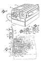
- a pressure detector for use in a syringe infusion pump system 11 for administering parenteral fluid to a human patient.
- the fluid is delivered to the patient in conventional fashion through a length of tubing 13 connected to a syringe 15.
- the pressure detector includes a frame 17 and a pressure diaphragm 19, which is coupled to the tubing and has a flexible membrane 21 that is movable in accordance with the fluid pressure in the tubing.
- the pressure diaphragm is installed in a special receptacle 23 on the frame.
- the pressure detector provides an electrical signal whenever the pressure diaphragm is not installed in the receptacle, and, if it is installed, whenever the pressure in the tubing is determined to exceed a prescribed threshold.
- the pressure detector further includes a follower assembly 25 mounted in the frame 17, adjacent to the pressure diaphragm receptacle 23, for linear movement in accordance with movement of the flexible membrane 21, along with first and second electrical contact assemblies 27a and 27b, respectively, for producing the aforementioned electrical signal.
- Each contact assembly includes an elongated, flexible contact spring 29a or 29b and an electrical contact 31 a or 31 b.
- the two contact springs are substantially parallel to each other and mounted at fixed ends thereof to the frame 17.
- the two electrical contacts are mounted on the free ends of their respective contact springs, in confronting relationship.
- the follower assembly is engageable with the two contact springs, to move the two electrical contacts apart from each other whenever the pressure diaphragm 19 is not installed in the receptacle or, if the diaphragm is properly installed, whenever the pressure in the tubing 13 exceeds the prescribed threshold.
- the aforementioned electrical signal is thereby provided on a pair of electrical leads 33a and 33b coupled to the respective contacts 31a a and 31 b.
- the pressure diaphragm 19 includes a rigid body portion 35 having an annular flange 37 that surrounds the flexible membrane 21.
- the resilient membrane is substantially planar and disc-shaped, in its unstressed condition, as shown by the solid line 21 in Fig. 2. As the fluid pressure in the tubing 13 increases, however, the membrane bulges outwardly from the flange by a corresponding amount, as shown by the phantom line 21' in Fig. 2.
- the receptacle 23 for retaining the pressure diaphragm 19 in its prescribed position on the frame 17 includes an inwardly-projecting flange 39 that defines a slot 41 for receiving the outwardly-projecting flange 37 of the diaphragm.
- the diaphragm is installed by manually inserting its flange into the slot, where it is held in place by the follower assembly 25, which urges it outwardly against the inwardly-facing surface of the receptacle flange.
- the pressure detector frame 17 provides support for the diaphragm receptacle 23 and also houses the follower assembly 25 and the first and second electrical contact assemblies 27a and 27b. It includes an outer housing member 43, an inner housing member 45, and a spacer ring 47, secured rigidly together by any suitable means, such as screws 49.
- the spacer ring is interposed between the outer and inner housing members, with the fixed end of the first contact spring 29a positioned between the outer member and the spacer ring, and the fixed end of the second contact spring 29b positioned between the inner member and the spacer ring.
- the frame further includes an end cap 51 fixed to the inner housing member. All of the frame elements are preferably molded from a suitable plastic material, to provide electrical insulation for the two contact springs.
- the follower assembly 25 includes a face member 53, a shaft 55, and spring biasing means 57, all axially aligned with each other and housed within the frame 17.
- the shaft is urged outwardly by the spring biasing means into engagement with the face member, which, in turn, is urged into engagement with the flexible membrane 21 of the installed pressure diaphragm 19.
- the shaft is slidably received in bores 59 and 61 formed in the inner housing member 45 and the end cap 51, respectively.
- the face member 53 is retained in its position in the frame by a flexible, annular ring 63 that is seated in annular seats 65 and 67 formed in the face member and the outer housing member 43, respectively.
- the annular ring also functions to seal the interior of the frame, to prevent contamination by dust and other foreign particles.
- the face member is also retained within the frame by an inwardly-projecting annular flange 69 on the outer housing member, which functions as a stop for an outwardly-projecting annular lip 71 on the face member.
- the face member further includes a plurality of circumferentially-spaced slots 73, to facilitate insertion of the face member lip 71 past the outer housing member flange 69.
- a shoulder 75 on the face member is engageable with the outer housing member flange, to prevent insertion of the face member too far into the frame.
- the follower shaft 55 includes a collar 77 that projects into the spacing between the two contact springs 29a and 29b.
- the collar functions as a control finger that engages the contact springs and thereby moves the two electrical contacts 31 a and 31 b toward or away from each other in accordance with the position of the shaft.
- the face member 53 and shaft 55 are urged inwardly by the diaphragm membrane 21 against the resistance of the spring biasing means 57.
- the resistance of the spring biasing means is overcome, and the face member and shaft are moved to a high pressure position. In this position, the shaft collar 77 engages the second contact spring 29b, to move it and the second contact 31 b away from the first contact spring 29a and the first contact 31 a. This restores the open circuit condition in the two electrical leads 33a and 33b. If the fluid pressure again drops below the prescribed threshold, the spring biasing means urges the shaft, and thus the shaft collar, outwardly, to bring the second contact back into electrical contact with the first contact (Fig. 3).
- the pressure detector further includes a finger 79 integral with the spacer ring 47 of the frame 17 and disposed between the two contact springs 29a and 29b. It functions to retain the second contact spring 29b whenever the shaft collar 77 engages the first contact spring 29a (Fig. 2), and to retain the first contact spring whenever the collar engages the second contact spring (Fig. 4).
- the spring biasing means 57 for urging the follower assembly 25 outwardly against the flexible membrane 21 of the pressure diaphragm 19 includes first and second coil springs 81 and 83, respectively.
- the two springs surround a reduced- diameter portion 85 of the follower shaft 55, in a chamber 87 formed by the inner housing member 45 and the end cap 51.
- the first coil spring 81 is disposed between a first annular shoulder 89 on the follower shaft 55 and the innerface of the end cap 51, inside an annular spring retaining wall 91. It provides a continuous outward force on the shaft, to urge the follower assembly to the initial position whenever the pressure diaphragm 19 is not installed. The force is small enough to be overcome readily by a manual insertion of the diaphragm into the receptacle 23.
- the second coil spring 83 surrounds the first spring 81 and is disposed between a flat ring 93 that surrounds the shaft 55 at the outer end of the chamber 87, and the inner face of the end cap 51, immediately outside the spring retaining wall 91.
- the follower shaft 55 includes a second annular shoulder 95 engageable with the flat ring, and thus the second spring, only when the shaft has been urged inwardly by the diaphragm membrane 21 to the intermediate position (Fig. 3). Only when the pressure in the fluid line exceeds the prescribed threshold, is there sufficient force to overcome the biasing force of the second spring, and thereby to move the follower assembly 25 to the high pressure position.
- the present invention provides an improved pressure detector for particular use in a system for administering parenteral fluid to a human patient.
- the pressure detector includes a conventional pressure diaphragm having a flexible membrane that is movable in accordance with the pressure of the fluid being administered.
- the detector further includes a special follower assembly and an associated pair of electrical contacts, for detecting both an installation of the pressure diaphragm and the relative position of its flexible membrane and thereby providing an electrical signal whenever the diaphragm is not installed and, if it is installed, whenever the fluid pressure exceeds a prescribed threshold.
Landscapes
- Physics & Mathematics (AREA)
- Fluid Mechanics (AREA)
- Infusion, Injection, And Reservoir Apparatuses (AREA)
- Switches Operated By Changes In Physical Conditions (AREA)
- External Artificial Organs (AREA)
- Measuring Fluid Pressure (AREA)
Applications Claiming Priority (2)
| Application Number | Priority Date | Filing Date | Title |
|---|---|---|---|
| US06/216,764 US4404440A (en) | 1980-12-15 | 1980-12-15 | Apparatus for detecting when the pressure detector in a fluid line exceeds a prescribed threshold |
| US216764 | 1980-12-15 |
Publications (4)
| Publication Number | Publication Date |
|---|---|
| EP0066607A1 EP0066607A1 (en) | 1982-12-15 |
| EP0066607A4 EP0066607A4 (en) | 1983-06-24 |
| EP0066607B1 EP0066607B1 (en) | 1985-09-18 |
| EP0066607B2 true EP0066607B2 (en) | 1989-03-22 |
Family
ID=22808415
Family Applications (1)
| Application Number | Title | Priority Date | Filing Date |
|---|---|---|---|
| EP82900271A Expired EP0066607B2 (en) | 1980-12-15 | 1981-11-27 | Pressure detector |
Country Status (6)
| Country | Link |
|---|---|
| US (1) | US4404440A (Direct) |
| EP (1) | EP0066607B2 (Direct) |
| JP (1) | JPH0132611B2 (Direct) |
| CA (1) | CA1165136A (Direct) |
| DE (1) | DE3172391D1 (Direct) |
| WO (1) | WO1982002114A1 (Direct) |
Families Citing this family (12)
| Publication number | Priority date | Publication date | Assignee | Title |
|---|---|---|---|---|
| FR2497543B1 (fr) * | 1981-01-07 | 1986-08-29 | Imed Corp | Mecanismes et procedes pour controler l'ecoulement d'un fluide vers un recepteur et convertir une pompe en controleur ainsi que controler la pression du fluide |
| US4503301A (en) * | 1983-03-24 | 1985-03-05 | American Standard Inc. | Differential fluid pressure switch |
| US4501583A (en) * | 1983-06-15 | 1985-02-26 | Extracorporeal, Inc. | Hemodialysis access monitors |
| DE3838689C1 (en) * | 1988-11-15 | 1990-06-28 | Fresenius Ag, 6380 Bad Homburg, De | Method for the continuous measurement of the pressure in a flexible fluid line for medical purposes, as well as a device for carrying out the method |
| US5015808A (en) * | 1989-12-22 | 1991-05-14 | Texas Instruments Incorporated | Normally open pressure switch |
| US6221045B1 (en) | 1995-04-20 | 2001-04-24 | Acist Medical Systems, Inc. | Angiographic injector system with automatic high/low pressure switching |
| KR20020003676A (ko) * | 2000-06-24 | 2002-01-15 | 전계익 | 레이저 편위계 |
| US6625394B2 (en) * | 2001-12-21 | 2003-09-23 | Eastman Kodak Company | Two-shot molded seal integrity indicator, underwater camera, and method |
| US7303175B2 (en) * | 2004-07-16 | 2007-12-04 | Cardinal Health 303, Inc. | Automatic clamp apparatus having lateral motion resistance for IV infusion sets |
| US7124996B2 (en) * | 2004-07-16 | 2006-10-24 | Cardinal Health 303, Inc. | Automatic clamp apparatus for IV infusion sets used in pump devices |
| USD556904S1 (en) | 2004-07-16 | 2007-12-04 | Cardinal Health 303, Inc. | Automatic clamp device with offset release tab |
| US11484645B2 (en) | 2020-11-18 | 2022-11-01 | Perceptive Medical Inc. | Systems and components for regulating fluid infusion to a patient |
Family Cites Families (7)
| Publication number | Priority date | Publication date | Assignee | Title |
|---|---|---|---|---|
| US2086264A (en) * | 1937-07-06 | Ceecbit controller | ||
| US2996588A (en) * | 1958-12-05 | 1961-08-15 | Power Brake Parts Mfg Co | Fluid pressure operated electrical switch assembly |
| US3304381A (en) * | 1965-09-02 | 1967-02-14 | Triex Inc | Caution light apparatus to indicate vehicle deceleration |
| US3665156A (en) * | 1970-09-08 | 1972-05-23 | Herbert P Lee | Heating-element protector for electric water-heater |
| CH599786A5 (Direct) * | 1975-10-24 | 1978-05-31 | Hoffmann La Roche | |
| JPS52119989A (en) * | 1976-04-02 | 1977-10-07 | Hitachi Ltd | Air-fuel ratio sensor |
| SE403004B (sv) * | 1976-12-03 | 1978-07-24 | Gambro Ab | Tryckvakt |
-
1980
- 1980-12-15 US US06/216,764 patent/US4404440A/en not_active Expired - Fee Related
-
1981
- 1981-11-26 CA CA000390947A patent/CA1165136A/en not_active Expired
- 1981-11-27 WO PCT/US1981/001591 patent/WO1982002114A1/en not_active Ceased
- 1981-11-27 EP EP82900271A patent/EP0066607B2/en not_active Expired
- 1981-11-27 JP JP57500337A patent/JPH0132611B2/ja not_active Expired
- 1981-11-27 DE DE8282900271T patent/DE3172391D1/de not_active Expired
Also Published As
| Publication number | Publication date |
|---|---|
| WO1982002114A1 (en) | 1982-06-24 |
| DE3172391D1 (en) | 1985-10-24 |
| JPS57501982A (Direct) | 1982-11-04 |
| US4404440A (en) | 1983-09-13 |
| EP0066607A4 (en) | 1983-06-24 |
| JPH0132611B2 (Direct) | 1989-07-07 |
| CA1165136A (en) | 1984-04-10 |
| EP0066607B1 (en) | 1985-09-18 |
| EP0066607A1 (en) | 1982-12-15 |
Similar Documents
| Publication | Publication Date | Title |
|---|---|---|
| EP0066607B2 (en) | Pressure detector | |
| US4394862A (en) | Metering apparatus with downline pressure monitoring system | |
| US4758228A (en) | Medical infusion pump with sensors | |
| US4468222A (en) | Intravenous liquid pumping system and method | |
| EP0066613B1 (en) | Pressure diaphragm | |
| US4126132A (en) | Intravenous and intra arterial delivery system | |
| EP2621557B1 (en) | Pressure sensor seal | |
| EP0319275B1 (en) | Patient-side occlusion detection system for a medication infusion system | |
| EP0319279B1 (en) | Cassette loading and latching apparatus for a medication infusion system | |
| EP0319278B1 (en) | Disposable cassette for a medication infusion system | |
| US5710401A (en) | Volumetric pump/valve | |
| US5840058A (en) | Infusion pump with disposable tubing and size indicating means | |
| EP0416912A1 (en) | Automatic tubing lock for ultrasonic sensor interface | |
| CA2144445A1 (en) | Force sensor assembly for pressure measurement for pump | |
| EP4410327A1 (en) | Infusion system with sensor system having reduced compliance sensitivity | |
| JPH0775670A (ja) | シリンジポンプ用圧力制限器 | |
| WO2011064615A1 (en) | Drip device for medicinal fluids and the like | |
| AU7454981A (en) | Metering apparatus with downline pressure monitoring system | |
| HK1182973A (en) | Pressure sensor seal | |
| HK1182973B (en) | Pressure sensor seal |
Legal Events
| Date | Code | Title | Description |
|---|---|---|---|
| PUAI | Public reference made under article 153(3) epc to a published international application that has entered the european phase |
Free format text: ORIGINAL CODE: 0009012 |
|
| AK | Designated contracting states |
Designated state(s): CH DE FR GB LI |
|
| 17P | Request for examination filed |
Effective date: 19821119 |
|
| RBV | Designated contracting states (corrected) |
Designated state(s): CH DE FR GB LI |
|
| GRAA | (expected) grant |
Free format text: ORIGINAL CODE: 0009210 |
|
| AK | Designated contracting states |
Designated state(s): CH DE FR GB LI |
|
| REF | Corresponds to: |
Ref document number: 3172391 Country of ref document: DE Date of ref document: 19851024 |
|
| ET | Fr: translation filed | ||
| PLBI | Opposition filed |
Free format text: ORIGINAL CODE: 0009260 |
|
| 26 | Opposition filed |
Opponent name: FRESENIUS AG Effective date: 19860613 |
|
| PUAH | Patent maintained in amended form |
Free format text: ORIGINAL CODE: 0009272 |
|
| STAA | Information on the status of an ep patent application or granted ep patent |
Free format text: STATUS: PATENT MAINTAINED AS AMENDED |
|
| 27A | Patent maintained in amended form |
Effective date: 19890322 |
|
| AK | Designated contracting states |
Kind code of ref document: B2 Designated state(s): CH DE FR GB LI |
|
| ET3 | Fr: translation filed ** decision concerning opposition | ||
| PGFP | Annual fee paid to national office [announced via postgrant information from national office to epo] |
Ref country code: CH Payment date: 19950110 Year of fee payment: 14 |
|
| PG25 | Lapsed in a contracting state [announced via postgrant information from national office to epo] |
Ref country code: LI Effective date: 19951130 Ref country code: CH Effective date: 19951130 |
|
| REG | Reference to a national code |
Ref country code: CH Ref legal event code: PL |
|
| REG | Reference to a national code |
Ref country code: FR Ref legal event code: CD Ref country code: FR Ref legal event code: CA |
|
| PGFP | Annual fee paid to national office [announced via postgrant information from national office to epo] |
Ref country code: GB Payment date: 19991102 Year of fee payment: 19 Ref country code: FR Payment date: 19991102 Year of fee payment: 19 Ref country code: DE Payment date: 19991102 Year of fee payment: 19 |
|
| PG25 | Lapsed in a contracting state [announced via postgrant information from national office to epo] |
Ref country code: GB Free format text: LAPSE BECAUSE OF NON-PAYMENT OF DUE FEES Effective date: 20001127 |
|
| GBPC | Gb: european patent ceased through non-payment of renewal fee |
Effective date: 20001127 |
|
| PG25 | Lapsed in a contracting state [announced via postgrant information from national office to epo] |
Ref country code: FR Free format text: LAPSE BECAUSE OF NON-PAYMENT OF DUE FEES Effective date: 20010731 |
|
| PG25 | Lapsed in a contracting state [announced via postgrant information from national office to epo] |
Ref country code: DE Free format text: LAPSE BECAUSE OF NON-PAYMENT OF DUE FEES Effective date: 20010801 |
|
| REG | Reference to a national code |
Ref country code: FR Ref legal event code: ST |