EP0066472A1 - Explosive gas detector - Google Patents
Explosive gas detector Download PDFInfo
- Publication number
- EP0066472A1 EP0066472A1 EP82302797A EP82302797A EP0066472A1 EP 0066472 A1 EP0066472 A1 EP 0066472A1 EP 82302797 A EP82302797 A EP 82302797A EP 82302797 A EP82302797 A EP 82302797A EP 0066472 A1 EP0066472 A1 EP 0066472A1
- Authority
- EP
- European Patent Office
- Prior art keywords
- lamp
- detector
- gas detector
- gas
- sensing head
- Prior art date
- Legal status (The legal status is an assumption and is not a legal conclusion. Google has not performed a legal analysis and makes no representation as to the accuracy of the status listed.)
- Withdrawn
Links
Images


Classifications
-
- G—PHYSICS
- G08—SIGNALLING
- G08B—SIGNALLING OR CALLING SYSTEMS; ORDER TELEGRAPHS; ALARM SYSTEMS
- G08B17/00—Fire alarms; Alarms responsive to explosion
- G08B17/10—Actuation by presence of smoke or gases, e.g. automatic alarm devices for analysing flowing fluid materials by the use of optical means
- G08B17/117—Actuation by presence of smoke or gases, e.g. automatic alarm devices for analysing flowing fluid materials by the use of optical means by using a detection device for specific gases, e.g. combustion products, produced by the fire
-
- A—HUMAN NECESSITIES
- A42—HEADWEAR
- A42B—HATS; HEAD COVERINGS
- A42B3/00—Helmets; Helmet covers ; Other protective head coverings
- A42B3/04—Parts, details or accessories of helmets
- A42B3/0406—Accessories for helmets
- A42B3/0433—Detecting, signalling or lighting devices
- A42B3/046—Means for detecting hazards or accidents
Definitions
- This invention relates to a detector for explosive gases, particularly for detecting the presence of methane and/or carbon monoxide in underground mines.
- This arrangement has the advantage that the detector is disposed relatively high on the miner's body, and no pump is needed to bring the atmosphere to the detector for testing. Since the chief dangerous gases are light and tend to collect at the top of the mine excavation, it is particularly suitable for the detector to be mounted at the level of the miner's head.
- An object of the invention is to provide a miner's cap lamp arrangement in which these disadvantages are overcome or at least mitigated.
- an electrically operated explosive gas detector for use in conjunction with a miner's cap lamp unit which includes a lamp housing, the detector being adapted to draw power from a battery of the unit and having a sensing head which obtains a sample of atmosphere to be sensed directly from the atmosphere surrounding the sensing head itself, characterised in that the sensing head and its associated heat-sensitive components are mounted in a casing separate from the lamp housing.
- the casing for the sensing head and its associated heat-sensitive components may conveniently be fixed to the lamp housing directly or through brackets or the like which space this casing away from the lamp, or the casing may be mounted on a cable connecting the cap lamp to the battery.
- the sensing head preferably works on the diffusion principle.
- the invention also provides a miner's cap lamp unit including a battery and having an electrically operated gas detector connected to the battery of the unit and having a sensing head which obtains a sample of atmosphere to be sensed directly from the atmosphere surrounding the cap itself, the lamp having a switch wired together with the detector so that when the switch is turned on the lamp will only begin to operate correctly if the detector is in a working condition.
- the circuitry may be arranged so that when the lamp is first switched on and the detector is in a working condition, the lamp light first comes on and then flickers for a short period to indicate that the detector is in an operative condition, before the light becomes steady. If the detector is not in a working condition, the light will not flicker.
- the lamp when an explosive gas is detected the lamp preferably flickers so as to provide a clear indication of the presence of an explosive gas whilst still retaining sufficient illumination for the wearer to see his way away from the location of the gas.
- the detector casing may be mounted on the side or the top of the cap lamp or as mentioned earlier, on the cable leading from the battery to the lamp and preferably near the lamp, between the lamp housing and a clip which is usually provided on the side of the cap to guide the cable away from the front of the cap.
- the detector may be included in newly constructed cap lamps, or may be fitted to existing lamps.
- Cap lamps are usually held on to the helmet by a releasable fastening, so that the lamp on the end of its cable can be removed.
- This facility makes it possible to move the gas detector about to discover where the explosive gases are. For example, if the cable is long enough, the lamp with the detector can be raised at arm's length to see if there is a dangerous concentration of gases at the level of the hanging wall. Similarly, the lamp on the end of its lead could be lowered into a tank to test for explosive gases.
- the positioning of the detector at head level is desirable because explosive gases in general and methane and carbon monoxide in particular are both lighter than air and will collect at the top of a mine excavation.
- the sensing head is preferably of the gas-sensitive semi-conductor type and incorporates a stainless steel flashback arrestor and a sintered filter disc which may for example be of stainless steel, copper or brass.
- the electronic circuitry can suitably be provided in microship form arranged to operate an electro-mechanical relay which switches the light on and off through an oscillator.
- the circuitry and relay and other heat sensitive components are enclosed in the casing, which may be a moulded plastics body sealed by shock-resistant silicon rubber.
- the lamp housing 1 fitted on a helmet 22 in Figure 1 can be of any suitable type, with an on/off switch 2 in a circuit between a battery 14 and a bulb 3.
- the lamp housing 1 is connected to the battery 14 by means of a cable 4.
- operation of the switch 2 causes the lamp to light.
- a gas detector casing 5 is fixed to the top of the lamp housing 1.
- the detector casing 5 contains a sensing head 6 mounted to one side of the casing 5, and it is this sensing head which picks up the presence of explosive gases.
- the gas detector is connected into a circuit ( Figure 3) which includes the battery 14, the bulb 3 and the switch 2 by means of wiring which passes from the casing 5 directly into the lamp housing 1.
- the sensing head 6 is a gas-sensitive semi-conductor sensor based on n-type sintered Sn02. When combustible or reducing gases are adsorbed on the sensor surface, a marked decrease of electrical resistance across the sensor occurs.
- the electrical circuit of the sensor is shown in Figure 2, and this includes a heater coil 7 which raises the temperature of the sensor 8 above ambient temperature, to bring it into operation.
- the two terminals attached to each side of the semi-conductor 8 are connected internally of the sensor unit, and the sensor unit is then connected into an electrical circuit by means of the connections 9 and 10, so that the circuit reacts to changes in the resistance of the semi-conductor 8 between the connections 9 and 10.
- the sensing head 6 includes a stainless steel mesh flashback arrestor (not visible in the drawings), and a sintered filter disc 11 set in an aperture in the casing 5.
- the electrical circuit associated with the sensing head is in microchip form and operates a normally closed electromechanical relay 16 the circuit includes an oscillator comparator 18 and is incorporated in the circuit supplying the bulb 3.
- the function of the circuit is as follows:
- the current through the resistor 20 is preferably about half the current required for a normal bright light condition where the relay 16 is closed. This arrangement reduces the surges in the circuit which can reduce the effective life of the battery. Such surges would become particularly detrimental if the light was switched completely off when the relay 16 opened.
- the sensing head 6 can conveniently be of the type sold at the time of filing this application by Figaro Engineering Inc. of the United States of America under the designation TGG 812 or 813.
- the electrical circuit can be a hybrid type in a microchip form which draws a maximum current of 110 mA which will be insufficient to have any noticeable effect on the power available from the battery.
- the relay 16 can be a suitable electromechanical type working at an operational voltage of a minimum of 3,5 volts.
- the detector casing 5 can be removed from the lamp housing 1.
- the electrical cables 20 are shown broken but in practice suitable plugs and sockets are usually provided to facilitate electrically connecting the detector to the lamp. Detectors can thus be readily changed or replaced or added to a lamp casing as required.
- the detector casing 5 is secured to the lamp housing 1 by two bolts 23 and 24.
- a base plate 26 of the detector casing 5 is provided and is formed of a heat insulating material to reduce any transfer of heat from the lamp to the detector casing 5.
- the sensing device decribed can sense methane, hydrogen, hydrogen sulphide and carbon monoxide, which are the main dangerous gases underground.
- the sensing device can be adjusted to detect the following gas concentrations:
- the detector described provides a continuous monitoring function of the atmosphere just above the miner's head, i.e. in the area where the highest concentration of explosive gases will build up. No pump is necessary to pass the gases over the detector, and thus a possible additonal source of battery drain is avoided.
- the sensing head 6 may be physically separated from the circuitry in the casing 5, for instance by locating the sensing head 6 on the cable 4. If this is done, it will be advantageous to mount at the sensing head 6 near the point where the cable 4 enters the lamp housing 1, so that the sensing head will be at the highest point for reasons already given.
- the invention extends to mounting of the sensing head and/or the electronic circuitry at any point along the length of the cord between the cap lamp and the battery 14, usually worn at the miner's waist.
- the sensing head may be mounted apart from the cap lamp or its cord, provided that electricity for the sensing head and its associated circuitry is still drawn from the battery.
- FIG. 6 illustrates an embodiment in which a gas detector casing 30 containing components similar to those described above with reference to the gas detector of Figures 1 to 5 is attached by means of metal brackets 32,34 and fixing bolts 36,38 to the top of a housing 40 of a miner's cap lamp.
- the lamp is adapted to be removably attached to a miner's helmet by a clip 42 or other conventional means.
- a short length of flexible cable 44 connects the circuitry of the gas detector in the casing 30 to the circuitry of the lamp, which is powered by a battery (not shown) at the end of a cable 46.
- Glands 48,50 are provided to ensure the sealing of the cables 44 and 46 respectively where they enter the housing 40, and a similar gland (not visible) is provided on the gas detector casing 30 where the upper end of the cable 44 enters this casing.
- the casing 30 has a window fitted with a sintered disc 52 which is a part of the sensing head of the detector.
- a miner's helmet 60 is fitted with a cap lamp having a housing 62 that is powered by a battery (not shown) through a flexible cable 64.
- a clip 66 on the helmet towards its rear holds the cable away from the miner's face.
- a gas detector casing 68 is located in the cable 64 between the lamp housing 62 and the clip 66, and incorporates similar components to those described with reference to the earlier embodiments.
- the sintered filter 70 forming part of the sensing device of the gas detector is in this version a band which extends around the periphery of the casing 68.
- a portion 64A of the cable 64 between the gas detector casing 68 and the lamp housing 62 is modified to include the wires necessary to act upon the components of the lamp in the housing 62.
- the gas detector's heat-sensitive components are located in a casing that is separate from the lamp housing, and thus the possibility of damaging these components or impairing their functioning by exposure to the heat generated in the lamp is eliminated or at least reduced to acceptable levels.
- the invention allows a gas detector to be fitted to existing cap lamps with the minimum of structural changes to the cap lamp unit.
- the lamp and the gas detector also remain independently accessible and replaceable in the invention in the event that either needs repair or fails entirely.
Abstract
A miner's cap lamp operates in conjunction with a gas detector which is connected to the cap lamp battery and is exposed to gas directly around the gas detector, which is normally mounted on or nearby the miner's helmet (22). The detector is electrically connected to the lamp itself so that when a dangerous gas concentration is sensed, the lamp is caused to flash to provide a warning signal to the miner. The gas detector's sensing head and other heat-sensitive components are mounted in a casing (5) that is separate from the lamp housing (1) and are therefore protected from heat generated by the lamp.
Description
- This invention relates to a detector for explosive gases, particularly for detecting the presence of methane and/or carbon monoxide in underground mines.
- Many different gas detectors for use in underground mines are already known. Some of these detectors are units which have to be carried, rather than being worn on the person. They therefore have the disadvantage that they can be put down and forgotten and that inevitably they are not carried by their owner all the time. There are thus times when the owner of the device is not in a position to be given a warning of the presence of explosive gas. It is of course also inconvenient to have to carry an extra item of equipment.
- There are also electronically-operating detectors which are worn on the body, generally requiring a pump to pump the'atmosphere to be sensed across a detector element. The use of a pump is an undesirable drain on battery power.
- It is known from United States patent 4,263,588 to provide a miner's helmet with a lamp which incorporates a detector for signalling the presence of dangerous gases. The lamp and detector are described as being in some cases integral with the helmet, or the lamp housing (including a compartment in which the electronic circuitry for the detecting and'signalling mechanisms are contained) may be removable from the helmet. In either case the detector and the lamp are contained in a common housing. They draw power from a battery to which they are connected by a cable.
- This arrangement has the advantage that the detector is disposed relatively high on the miner's body, and no pump is needed to bring the atmosphere to the detector for testing. Since the chief dangerous gases are light and tend to collect at the top of the mine excavation, it is particularly suitable for the detector to be mounted at the level of the miner's head.
- However the arrangement described in United States patent 4,263,588 has the substantial drawback that the detector and the lamp are unitary. Since the temperature of the filaments in a modern miner's cap lamp may exceed 1000°C, and the temperature in the space between the globes and the reflector exceeds 100°C, the heat build-up is considerable, and heat-sensitive components of the detector in the common housing tend to be damaged, particularly as the detector itself generates heat. Further, existing lamps cannot be fitted with a detector as and when required. Also, the detector, which is relatively complex and delicate in comparison with the lamp (apart from the lamp globes) cannot be replaced independently of the lamp should the detector fail. The common housing also tends to limit the size of the filter (usually a sintered disc) used at the air inlet to the detector. As this disc may easily clog it should be made as large as possible.
- An object of the invention is to provide a miner's cap lamp arrangement in which these disadvantages are overcome or at least mitigated.
- According to the present invention, there is provided an electrically operated explosive gas detector for use in conjunction with a miner's cap lamp unit which includes a lamp housing, the detector being adapted to draw power from a battery of the unit and having a sensing head which obtains a sample of atmosphere to be sensed directly from the atmosphere surrounding the sensing head itself, characterised in that the sensing head and its associated heat-sensitive components are mounted in a casing separate from the lamp housing.
- The casing for the sensing head and its associated heat-sensitive components may conveniently be fixed to the lamp housing directly or through brackets or the like which space this casing away from the lamp, or the casing may be mounted on a cable connecting the cap lamp to the battery.
- The sensing head preferably works on the diffusion principle.
- The invention also provides a miner's cap lamp unit including a battery and having an electrically operated gas detector connected to the battery of the unit and having a sensing head which obtains a sample of atmosphere to be sensed directly from the atmosphere surrounding the cap itself, the lamp having a switch wired together with the detector so that when the switch is turned on the lamp will only begin to operate correctly if the detector is in a working condition.
- For example, the circuitry may be arranged so that when the lamp is first switched on and the detector is in a working condition, the lamp light first comes on and then flickers for a short period to indicate that the detector is in an operative condition, before the light becomes steady. If the detector is not in a working condition, the light will not flicker.
- Also, when an explosive gas is detected the lamp preferably flickers so as to provide a clear indication of the presence of an explosive gas whilst still retaining sufficient illumination for the wearer to see his way away from the location of the gas.
- The detector casing may be mounted on the side or the top of the cap lamp or as mentioned earlier, on the cable leading from the battery to the lamp and preferably near the lamp, between the lamp housing and a clip which is usually provided on the side of the cap to guide the cable away from the front of the cap. In any event the detector may be included in newly constructed cap lamps, or may be fitted to existing lamps.
- Cap lamps are usually held on to the helmet by a releasable fastening, so that the lamp on the end of its cable can be removed. This facility makes it possible to move the gas detector about to discover where the explosive gases are. For example, if the cable is long enough, the lamp with the detector can be raised at arm's length to see if there is a dangerous concentration of gases at the level of the hanging wall. Similarly, the lamp on the end of its lead could be lowered into a tank to test for explosive gases.
- Furthermore, the positioning of the detector at head level is desirable because explosive gases in general and methane and carbon monoxide in particular are both lighter than air and will collect at the top of a mine excavation.
- The sensing head is preferably of the gas-sensitive semi-conductor type and incorporates a stainless steel flashback arrestor and a sintered filter disc which may for example be of stainless steel, copper or brass. The electronic circuitry can suitably be provided in microship form arranged to operate an electro-mechanical relay which switches the light on and off through an oscillator. The circuitry and relay and other heat sensitive components are enclosed in the casing, which may be a moulded plastics body sealed by shock-resistant silicon rubber.
- The invention will now be further described, by way of example, with reference to the accompanying drawings, in which:
- Figure 1 is a perspective view of a miner's helmet fitted with a cap lamp and gas detector according to the invention;
- Figure 2 is a diagrammatic view of the electronic components in the sensing head of the gas detector of Figure 1;
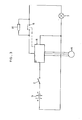
- Figure 3 is a schematic circuit diagram of the gas detector of Figure 1;
- Figure 4 is an exploded perspective view of the lamp and gas detector of Figure 1;
- Figure 5 is a cross-sectional view through the lamp and gas detector of Figure 1, taken on the line V-V in Figure 1;
- Figure 6 is a perspective view of an alternative cap lamp and gas detector for mounting on a miner's helmet of the type seen in Figure 1; and
- Figure 7 is a plan view of a miner's helmet fitted with a further alternative arrangement of a cap lamp and gas detector.
- The
lamp housing 1 fitted on ahelmet 22 in Figure 1 can be of any suitable type, with an on/offswitch 2 in a circuit between abattery 14 and abulb 3. Thelamp housing 1 is connected to thebattery 14 by means of a cable 4. As is known, operation of theswitch 2 causes the lamp to light. - A
gas detector casing 5 is fixed to the top of thelamp housing 1. Thedetector casing 5 contains asensing head 6 mounted to one side of thecasing 5, and it is this sensing head which picks up the presence of explosive gases. - The gas detector is connected into a circuit (Figure 3) which includes the
battery 14, thebulb 3 and theswitch 2 by means of wiring which passes from thecasing 5 directly into thelamp housing 1. - The sensing
head 6 is a gas-sensitive semi-conductor sensor based on n-type sintered Sn02. When combustible or reducing gases are adsorbed on the sensor surface, a marked decrease of electrical resistance across the sensor occurs. The electrical circuit of the sensor is shown in Figure 2, and this includes aheater coil 7 which raises the temperature of thesensor 8 above ambient temperature, to bring it into operation. The two terminals attached to each side of the semi-conductor 8 are connected internally of the sensor unit, and the sensor unit is then connected into an electrical circuit by means of theconnections connections sensing head 6 includes a stainless steel mesh flashback arrestor (not visible in the drawings), and a sinteredfilter disc 11 set in an aperture in thecasing 5. - The electrical circuit associated with the sensing head is in microchip form and operates a normally closed
electromechanical relay 16 the circuit includes anoscillator comparator 18 and is incorporated in the circuit supplying thebulb 3. The function of the circuit is as follows: - When the
switch 2 is initially operated, thebulb 3 lights up and at the same time current is fed to the heating coil 7 (not shown in Figure 3). Until the semi-conductor 8 reaches its operating temperature its resistance is below a predetermined value so that theoscillator comparator 18 in the electrical circuit causes the light to flash at approximately one cycle per second for about 10 to 120 seconds. When the operating temperature of the semi-conductor 8 is reached due to the heating by thecoil 7, the light becomes steady again and remains steady. When an explosive gas is detected thereafter by the sensing head, the resistance of the semi-conductor decreases, and this causes the oscillator in the electrical circuit to be brought into operation again to open and close therelay 16 to cause the light to flash. When therelay 16 is open, a small current passes to thebulb 3 through aresistor 20. The light therefore actually switches between bright and dim. The flashing light then provides an indication of the presence of an explosive gas. When the gas concentration again decreases, the resistance of the semi-conductor rises, and the oscillator is no longer activated so that the light again becomes steady. - It will be noted that due to the current path through the
resistor 20 the light remains on even when therelay 16 is open, in practice the current through the resistor is preferably about half the current required for a normal bright light condition where therelay 16 is closed. This arrangement reduces the surges in the circuit which can reduce the effective life of the battery. Such surges would become particularly detrimental if the light was switched completely off when therelay 16 opened. - In practice, when a miner collects his cap lamp unit before going down a mine, he will switch the lamp on. Normally the light will flash for a period before becoming steady, and the miner will not go down the mine unless and until the light has become steady, indicating that the sensing device is operational. To guard against the unlikely possibility of the sensing device failing whilst the miner is down the mine, it may be possible to include in the electrical circuit a second oscillator circuit which will produce oscillations with a different characteristic on failure of the sensing device.
- The
sensing head 6 can conveniently be of the type sold at the time of filing this application by Figaro Engineering Inc. of the United States of America under the designation TGG 812 or 813. - The electrical circuit can be a hybrid type in a microchip form which draws a maximum current of 110 mA which will be insufficient to have any noticeable effect on the power available from the battery. The
relay 16 can be a suitable electromechanical type working at an operational voltage of a minimum of 3,5 volts. - In Figure 4 it can be seen that the
detector casing 5 can be removed from thelamp housing 1. Theelectrical cables 20 are shown broken but in practice suitable plugs and sockets are usually provided to facilitate electrically connecting the detector to the lamp. Detectors can thus be readily changed or replaced or added to a lamp casing as required. Thedetector casing 5 is secured to thelamp housing 1 by twobolts - In Figure 5 it can be seen that a
base plate 26 of thedetector casing 5 is provided and is formed of a heat insulating material to reduce any transfer of heat from the lamp to thedetector casing 5. - The sensing device decribed can sense methane, hydrogen, hydrogen sulphide and carbon monoxide, which are the main dangerous gases underground. In particular, the sensing device can be adjusted to detect the following gas concentrations:
-
-
Methane 10 000 PPM by volume -
Hydrogen 30 PPM by volume -
Hydrogen Sulphide 10 PPM by volume - Carbon Monoxide 250 PPM by volume
-
-
Methane 10 000 PPM by volume -
Hydrogen 1 100 PPM by volume - Hydrogen Sulphide 300 PPM by volume
-
Carbon Monoxide 20 PPM by volume - Advantages of the detector described are that it provides a continuous monitoring function of the atmosphere just above the miner's head, i.e. in the area where the highest concentration of explosive gases will build up. No pump is necessary to pass the gases over the detector, and thus a possible additonal source of battery drain is avoided.
- The
sensing head 6 may be physically separated from the circuitry in thecasing 5, for instance by locating thesensing head 6 on the cable 4. If this is done, it will be advantageous to mount at thesensing head 6 near the point where the cable 4 enters thelamp housing 1, so that the sensing head will be at the highest point for reasons already given. However the invention extends to mounting of the sensing head and/or the electronic circuitry at any point along the length of the cord between the cap lamp and thebattery 14, usually worn at the miner's waist. - In other possible alternative arrangements, the sensing head may be mounted apart from the cap lamp or its cord, provided that electricity for the sensing head and its associated circuitry is still drawn from the battery.
- Figure 6 illustrates an embodiment in which a
gas detector casing 30 containing components similar to those described above with reference to the gas detector of Figures 1 to 5 is attached by means ofmetal brackets bolts housing 40 of a miner's cap lamp. The lamp is adapted to be removably attached to a miner's helmet by aclip 42 or other conventional means. A short length offlexible cable 44 connects the circuitry of the gas detector in thecasing 30 to the circuitry of the lamp, which is powered by a battery (not shown) at the end of acable 46.Glands cables housing 40, and a similar gland (not visible) is provided on thegas detector casing 30 where the upper end of thecable 44 enters this casing. Thecasing 30 has a window fitted with asintered disc 52 which is a part of the sensing head of the detector. - In Figure 7, a miner's
helmet 60 is fitted with a cap lamp having ahousing 62 that is powered by a battery (not shown) through aflexible cable 64. Aclip 66 on the helmet towards its rear holds the cable away from the miner's face. Agas detector casing 68 is located in thecable 64 between thelamp housing 62 and theclip 66, and incorporates similar components to those described with reference to the earlier embodiments. Thesintered filter 70 forming part of the sensing device of the gas detector is in this version a band which extends around the periphery of thecasing 68. A portion 64A of thecable 64 between thegas detector casing 68 and thelamp housing 62 is modified to include the wires necessary to act upon the components of the lamp in thehousing 62. - It will be clear that in the embodiment of Figure 7 the
gas detector housing 68, being located alongside rather than above thelamp housing 62, is unlikely to be damaged by contact with the hanging wall of the excavation. Further, since the gas detector's weight is located further rearward than in the previous embodiments, there is a lesser tendency in this version for the helmet to tip forwards on the miner's head. - In all the embodiments discussed the gas detector's heat-sensitive components are located in a casing that is separate from the lamp housing, and thus the possibility of damaging these components or impairing their functioning by exposure to the heat generated in the lamp is eliminated or at least reduced to acceptable levels. Further, the invention allows a gas detector to be fitted to existing cap lamps with the minimum of structural changes to the cap lamp unit. The lamp and the gas detector also remain independently accessible and replaceable in the invention in the event that either needs repair or fails entirely.
Claims (11)
1. An electrically operated explosive gas detector for use in conjunction with a miner's cap lamp which includes a lamp housing(1,40,62), the detector being adapted to draw power from a battery(14) of the unit and having a sensing head(6) which obtains a sample of atmosphere to be sensed directly from the atmosphere surrounding the sensing head(6) itself, characterised in that the sensing head (6) and its associated heat-sensitive components are mounted in at least one casing (5,30,68) separate from the lamp housing(1,40,62).
2. A gas detector as claimed in Claim 1, characterised in that the gas detector casing (5) is mounted directly on the lamp housing (1).
3. A gas detector as claimed in Claim 1, characterised in that the gas detector casing (5,30) is spaced a fixed distance away from the lamp housing (1,40).
4. A gas detector as claimed in Claim 1, characterised in that the gas detector casing (68) is located in a cable (64) connecting the cap lamp to the battery (14).
5. A gas detector as claimed in any preceding claim, characterised in that the sensing head (6) is a gas-sensitive semi-conductor sensor.
6. A gas detector as claimed in any preceding claim, characterised in that the sensing head (6) is connected in an electrical circuit which provides an activating signal for causing the lamp to flicker when a dangerous gas concentration is sensed.
7. A gas detecor as claimed in Claim 6, characterised in that the circuit includes an oscillator (18).
8. A gas detector as claimed in Claim 6 or Claim 7, characterised in that the sensing head (6) and the circuit are mounted together in a common casing (5,30,68).
9. A gas detector as claimed in Claim 6 or Claim 7, characterised in that the electrical circuit is housed apart from the sensing head (6).
10. A gas detector as claimed in any of the preceding claims wherein the circuit includes a switch (2) for the cap lamp, characterised in that the circuit is arranged so that the lamp will only operate steadily if the detector is in a working condition.
11. A gas detector as claimed in Claim 10, characterised in that the circuit is arranged so that when the lamp is first switched on, the lamp flickers from bright to dim for a short period and then (in the absence of a dangerous gas concentration) becomes steady to indicate that the detector is in a working condition.
Applications Claiming Priority (6)
| Application Number | Priority Date | Filing Date | Title |
|---|---|---|---|
| ZA813617 | 1981-05-29 | ||
| ZA813617 | 1981-05-29 | ||
| ZA816116 | 1981-09-03 | ||
| ZA816116 | 1981-09-03 | ||
| ZA82785 | 1982-02-08 | ||
| ZA820785 | 1982-02-08 |
Publications (1)
| Publication Number | Publication Date |
|---|---|
| EP0066472A1 true EP0066472A1 (en) | 1982-12-08 |
Family
ID=27420909
Family Applications (1)
| Application Number | Title | Priority Date | Filing Date |
|---|---|---|---|
| EP82302797A Withdrawn EP0066472A1 (en) | 1981-05-29 | 1982-06-01 | Explosive gas detector |
Country Status (2)
| Country | Link |
|---|---|
| EP (1) | EP0066472A1 (en) |
| AU (1) | AU8433982A (en) |
Cited By (7)
| Publication number | Priority date | Publication date | Assignee | Title |
|---|---|---|---|---|
| EP2016845A2 (en) * | 2007-07-20 | 2009-01-21 | Koehler-Bright Star Inc. | Electronic module adapter for headgear |
| GB2459944A (en) * | 2008-05-15 | 2009-11-18 | Draeger Safety Ag & Co Kgaa | Article of safety wear with gas alarm indicator |
| CN102062301A (en) * | 2010-10-13 | 2011-05-18 | 彭映斌 | Energy-saving multifunctional integrated mining lamp |
| CN107290385A (en) * | 2017-06-09 | 2017-10-24 | 公安部上海消防研究所 | Helmet flame resistance energy test device and its method of testing |
| US9885471B2 (en) | 2007-07-20 | 2018-02-06 | Koehler-Bright Star LLC | Multiple electronic tag holder |
| CN108703430A (en) * | 2018-05-15 | 2018-10-26 | 安徽天卓信息技术有限公司 | A kind of mining gas detection safety cap and its detection method |
| CN116293544A (en) * | 2023-05-10 | 2023-06-23 | 江苏恒械机械有限公司 | Portable lighting device for mine tunnel |
Families Citing this family (1)
| Publication number | Priority date | Publication date | Assignee | Title |
|---|---|---|---|---|
| CN113796616B (en) * | 2021-10-26 | 2023-08-04 | 西安科技大学 | Wearing warning device and warning method for safety equipment for coal mine safety management |
Citations (3)
| Publication number | Priority date | Publication date | Assignee | Title |
|---|---|---|---|---|
| FR1506941A (en) * | 1966-12-29 | 1967-12-22 | Inst Gornogo Dela Imeni Skochi | Portable thermochemical gas analyzer |
| EP0016351A1 (en) * | 1979-03-16 | 1980-10-01 | Cerberus Ag | Gas detection device for use in an environment where explosions may occur |
| US4263588A (en) * | 1979-07-25 | 1981-04-21 | Oldham France S.A. | Helmet-carried apparatus for detecting and signalling the presence of a dangerous gas in an atmosphere |
-
1982
- 1982-05-31 AU AU84339/82A patent/AU8433982A/en not_active Abandoned
- 1982-06-01 EP EP82302797A patent/EP0066472A1/en not_active Withdrawn
Patent Citations (3)
| Publication number | Priority date | Publication date | Assignee | Title |
|---|---|---|---|---|
| FR1506941A (en) * | 1966-12-29 | 1967-12-22 | Inst Gornogo Dela Imeni Skochi | Portable thermochemical gas analyzer |
| EP0016351A1 (en) * | 1979-03-16 | 1980-10-01 | Cerberus Ag | Gas detection device for use in an environment where explosions may occur |
| US4263588A (en) * | 1979-07-25 | 1981-04-21 | Oldham France S.A. | Helmet-carried apparatus for detecting and signalling the presence of a dangerous gas in an atmosphere |
Cited By (10)
| Publication number | Priority date | Publication date | Assignee | Title |
|---|---|---|---|---|
| EP2016845A2 (en) * | 2007-07-20 | 2009-01-21 | Koehler-Bright Star Inc. | Electronic module adapter for headgear |
| EP2016845A3 (en) * | 2007-07-20 | 2010-03-10 | Koehler-Bright Star Inc. | Electronic module adapter for headgear |
| AU2008203236B2 (en) * | 2007-07-20 | 2013-05-23 | Koehler-Bright Star, Inc. | Eletronic module adapter for headgear |
| US9885471B2 (en) | 2007-07-20 | 2018-02-06 | Koehler-Bright Star LLC | Multiple electronic tag holder |
| GB2459944A (en) * | 2008-05-15 | 2009-11-18 | Draeger Safety Ag & Co Kgaa | Article of safety wear with gas alarm indicator |
| US8103459B2 (en) | 2008-05-15 | 2012-01-24 | Dräger Safety AG & Co. KGaA | Safety clothing |
| CN102062301A (en) * | 2010-10-13 | 2011-05-18 | 彭映斌 | Energy-saving multifunctional integrated mining lamp |
| CN107290385A (en) * | 2017-06-09 | 2017-10-24 | 公安部上海消防研究所 | Helmet flame resistance energy test device and its method of testing |
| CN108703430A (en) * | 2018-05-15 | 2018-10-26 | 安徽天卓信息技术有限公司 | A kind of mining gas detection safety cap and its detection method |
| CN116293544A (en) * | 2023-05-10 | 2023-06-23 | 江苏恒械机械有限公司 | Portable lighting device for mine tunnel |
Also Published As
| Publication number | Publication date |
|---|---|
| AU8433982A (en) | 1982-12-02 |
Similar Documents
| Publication | Publication Date | Title |
|---|---|---|
| US4617561A (en) | Emergency light and smoke alarm system | |
| US5625345A (en) | Fire safety apparatus | |
| US9874342B1 (en) | Gas warning head lamp | |
| US5413097A (en) | Fan-supported gas mask and breathing equipment with adjustable fan output | |
| US3877291A (en) | Portable breath tester | |
| US5833350A (en) | Switch cover plate providing automatic emergency lighting | |
| US6417774B1 (en) | System and method for identifying unsafe temperature conditions | |
| US4263588A (en) | Helmet-carried apparatus for detecting and signalling the presence of a dangerous gas in an atmosphere | |
| CA2086408C (en) | Fiber-optic anticycling device for street lamps | |
| EP0066472A1 (en) | Explosive gas detector | |
| US4896145A (en) | Fixture for mounting a lampholder and fire detector | |
| US4996981A (en) | Apparatus for removing condensate from a sealed face visor and for indicating a dangerous environmental temperature | |
| KR960025256A (en) | Gas detection and alarm system to monitor gases such as carbon monoxide | |
| ES2239931T3 (en) | FUEL FILTER FOR DIESEL ENGINES WITH DIRECT HIGH PRESSURE INJECTION OF THE COMMON AND SIMILAR TYPE OF CONDUCT. | |
| US4131877A (en) | Low tire pressure indicator circuit | |
| US3659278A (en) | Fire and smoke alarm device | |
| CN106169214A (en) | A kind of multifunctional fire detecting alarm | |
| US2535950A (en) | Flammable gas detector | |
| CN101855176B (en) | Water treatment system with moisture detector | |
| CN219299198U (en) | Folding ladder with gas detection and illumination functions | |
| US3487394A (en) | Fail safe indicator of failures in heating apparatus | |
| GB2183334A (en) | Gas detector and mining machine | |
| CN216623463U (en) | A alarm device for methane gas detects | |
| GB2267594A (en) | Lighting apparatus | |
| GB2054156A (en) | Apparatus for Detecting and Signalling the Presence of a Dangerous Gas in an Atmosphere |
Legal Events
| Date | Code | Title | Description |
|---|---|---|---|
| PUAI | Public reference made under article 153(3) epc to a published international application that has entered the european phase |
Free format text: ORIGINAL CODE: 0009012 |
|
| AK | Designated contracting states |
Designated state(s): AT BE CH DE FR GB IT LU NL SE |
|
| ITCL | It: translation for ep claims filed |
Representative=s name: JACOBACCI CASETTA & PERANI S.P.A. |
|
| 17P | Request for examination filed |
Effective date: 19830603 |
|
| RAP1 | Party data changed (applicant data changed or rights of an application transferred) |
Owner name: GAS MONITORING SYSTEMS (PTY) LIMITED |
|
| STAA | Information on the status of an ep patent application or granted ep patent |
Free format text: STATUS: THE APPLICATION IS DEEMED TO BE WITHDRAWN |
|
| 18D | Application deemed to be withdrawn |
Effective date: 19850730 |
|
| RIN1 | Information on inventor provided before grant (corrected) |
Inventor name: LODEWICK, KEITH IAN |