EP0066352B1 - Tape transport system - Google Patents
Tape transport system Download PDFInfo
- Publication number
- EP0066352B1 EP0066352B1 EP82301037A EP82301037A EP0066352B1 EP 0066352 B1 EP0066352 B1 EP 0066352B1 EP 82301037 A EP82301037 A EP 82301037A EP 82301037 A EP82301037 A EP 82301037A EP 0066352 B1 EP0066352 B1 EP 0066352B1
- Authority
- EP
- European Patent Office
- Prior art keywords
- tape
- tension
- pulley halves
- rotation
- reel
- Prior art date
- Legal status (The legal status is an assumption and is not a legal conclusion. Google has not performed a legal analysis and makes no representation as to the accuracy of the status listed.)
- Expired
Links
- 230000008878 coupling Effects 0.000 claims description 10
- 238000010168 coupling process Methods 0.000 claims description 10
- 238000005859 coupling reaction Methods 0.000 claims description 10
- 230000005540 biological transmission Effects 0.000 claims description 8
- 238000006073 displacement reaction Methods 0.000 claims description 8
- 230000007246 mechanism Effects 0.000 claims description 6
- 230000004044 response Effects 0.000 claims description 5
- 238000000926 separation method Methods 0.000 claims description 3
- 230000033001 locomotion Effects 0.000 description 8
- 230000032258 transport Effects 0.000 description 8
- 230000008901 benefit Effects 0.000 description 4
- 230000001419 dependent effect Effects 0.000 description 2
- 230000002441 reversible effect Effects 0.000 description 2
- 230000009471 action Effects 0.000 description 1
- 230000001154 acute effect Effects 0.000 description 1
- 238000011109 contamination Methods 0.000 description 1
- 230000003247 decreasing effect Effects 0.000 description 1
- 230000013011 mating Effects 0.000 description 1
- 230000003287 optical effect Effects 0.000 description 1
- 239000007787 solid Substances 0.000 description 1
Images

Classifications
-
- G—PHYSICS
- G11—INFORMATION STORAGE
- G11B—INFORMATION STORAGE BASED ON RELATIVE MOVEMENT BETWEEN RECORD CARRIER AND TRANSDUCER
- G11B15/00—Driving, starting or stopping record carriers of filamentary or web form; Driving both such record carriers and heads; Guiding such record carriers or containers therefor; Control thereof; Control of operating function
- G11B15/18—Driving; Starting; Stopping; Arrangements for control or regulation thereof
- G11B15/46—Controlling, regulating, or indicating speed
- G11B15/50—Controlling, regulating, or indicating speed by mechanical linkage, e.g. clutch
-
- G—PHYSICS
- G11—INFORMATION STORAGE
- G11B—INFORMATION STORAGE BASED ON RELATIVE MOVEMENT BETWEEN RECORD CARRIER AND TRANSDUCER
- G11B15/00—Driving, starting or stopping record carriers of filamentary or web form; Driving both such record carriers and heads; Guiding such record carriers or containers therefor; Control thereof; Control of operating function
- G11B15/18—Driving; Starting; Stopping; Arrangements for control or regulation thereof
- G11B15/43—Control or regulation of mechanical tension of record carrier, e.g. tape tension
Definitions
- the invention relates to a tape tension control system for a tape transport arrangement of the type wherein a first reel having tape wound thereon supplies tape which is drawn therefrom by a tape drive mechanism, the drawn tape being collected on a second reel, the first and second reels being mechanically coupled to first and second shafts, respectively the tension control system comprising:
- first and second variable ratio coupling means arranged for rotatively coupling the first and second shafts to one another, whereby rotation of the first shaft is coupled to the second shaft to rotate the second shaft at a rate of rotation corresponding to a selected ratio with respect to a rate of rotation of the first shaft, said selected ratio of said rate of rotation of the first and second shafts being variable within a range of ratios.
- negator springs In capstan driven systems, negator springs have been used to ' provide for the differential motion between supply and take-up reels.
- a good example of a negator spring tension apparatus is described in U.S. Patent No. 4,145,016.
- Negator spring transports are useful to help achieve the precise control required with high-density recordings, however, such systems are heavy, and tape tension must be equalized by the use of complicated and expensive magnetic brakes or their equivalents.
- a tension control system as set out in the opening paragraph and being characterised by:
- first and said second variable coupling means mechanically interconnecting said first and said second variable coupling means, which each comprise first and second pulley halves, each said pulley half having a central axis of rotation and a respective friction surface for engaging said flexible drive transmission means, the respective first pulley halves being coaxially movably arranged with respect to the respective second pulley halves along respective axes of rotation;
- tension sensing means for detecting a tensile force in the tape directly, as it is collected onto the second reel and providing a tape tension signal which corresponds to said tensile force
- servo motor means responsive to said tape tension signal from said tension sensing means, said servo motor means being coupled between first and second independently rotatable portions of said second shaft to provide relative rotation therebetween, the first portion being coupled to the second reel and the second portion being coupled to said second variable coupling means for producing said relative coaxial displacement between said first and second pulley halves, thereby to select said selected ratio of said rate of rotation of the first and second shafts.
- Fig. 1 shows a cross-sectional view of an illustrative embodiment of the inventive web transport system.
- a supply reel 11 and a take-up reel 12 are stacked coaxially, as shown.
- Reels 11 and 12 are provided with respective hub portions 13 and 14 which are coupled to respective shafts 16 and 17.
- shaft 16 may be substantially in the form of a cylindrical solid, and provided with a spline portion 2b.
- a pair of pulley halves, 21 and 22, are mounted on spline portion 20 of shaft 16 so as to rotate with the shaft as reel 11 is rotated in response to the drawing of the tape by a capstan tape drive mechanism (not shown in this figure).
- Shaft 17, which is coupled to reel 12, is provided with a coaxial, central opening 30 through which shaft 16 is arranged.
- a gear 31 is coaxially affixed to shaft 17, so as to rotate with reel 12.
- Gear 31- is enmeshed with a further gear 32 which is concentrically coupled to a shaft 33.
- Gears 31 and 32 may be of the helical type, and, in this embodiment, may provide a -1:1 gear ratio.
- shaft 33 rotates at the same rotational speed as take-up reel 12, but in the opposite rotational direction.
- Shaft 33 is mechanically coupled to a housing of a servo motor 40.
- Servo motor 40 is provided with a screw threaded armature shaft 42, which rotates with respect to the housing of servo motor 40 in response to the application of electrical signals at slip rings 43 and 44 which are in electrical communication with respective electrical contact members 46 and 47.
- Screw threaded armature shaft 42 is provided with a pair of coaxially arranged pulley halves 51 and 52.
- Pulley halves 51 and 52 are constrained to rotate with the housing of servo motor 40 by a key 53 which permits pulley halves 51 and 52 to move with respect to one another on the longitudinal axis of screw threaded armature shaft 42, but locks the pulley halves so as to rotate synchronously with the servo motor housing, and consequently with tape reel 12.
- the application of electrical signals, the nature and origin of which will be described hereinbelow, to contact members 46 and 47 causes screw threaded armature shaft 42 to rotate so as to responsively vary the amount of separation between pulley halves 51 and 52.
- the pulley halves on screw threaded shaft 42 are coupled to the pulley halves on shaft 16 by a belt 55 having a fixed loop length.
- Belt 55 transfers rotational motion between respective pairs of pulley halves in accordance with a variable transfer ratio.
- the application of an appropriate signal at electrical contact members 46 and 47 rotates shaft 42 in a direction which causes pulley halves 51 and 52 to separate coaxially, as shown. This separation permits belt 55 to be moved. radially inward towards screw threaded shaft 42, so as to effectively reduce the diameter of pulley halves 51 and 52.
- the effective diameter of pulley halves 51 and 52 is reduced, the effective diameter of pulley halves 21 and 22 is increased.
- screw threaded armature shaft 42 will rotate in an opposite direction so as to cause pulley halves 51 and 52 to move axially closer to one another.
- This causes belt 55 to be moved radially outward from the screw threaded shaft 42, thereby increasing the effective radius of pulley halves 51 and 52, with respect to the axis of rotation of screw threaded armature shaft 42.
- belt 55 is urged outward along pulley halves 21 and 22, by the bringing together of the pulley halves, the belt is caused to be moved radially inward on pulley halves 21 and 22, so as to be disposed at a shorter radius with respect to the longitudinal axis of shaft 16.
- the ratio of effective diameters between the diameter of pulley halves 51 and 52 and pulley halves 21 and 22, may be advantageously adjusted by the application of appropriate electrical signals at contact members 46 and 47 so as to rotate screw threaded armature shaft 42 in a predetermined direction, and thereby adjust the distance between pulley halves 51 and 52.
- the ratio of pulley diameters varies exponentially with the distance between pulley halves 51 and 52. This results from the fact that the axial motion between pulley halves 51 and 52 causes variations in the effective diameters of all of the pulley halves.
- the effective diameter of one pair of pulley halves is increased, the effective diameter of the other pair is decreased, and vice versa.
- the pulley halves have frictional surfaces which slope linearly with respect to pulley radius, in the form of truncated cones which are arranged coaxially inverted with respect to one another so as to produce two predetermined frictional surface angles therebetween, the variations in the ratio of pulley diameters varies exponentially with variation in the coaxial distance between pulley halves 51 and 52.
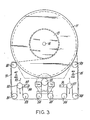
- Fig. 2 shows an embodiment of the invention which is particularly suited for aeronautic and space applications.
- tape reels 11 and 12 may be mounted in an hermetically sealed cartridge 60 which mates with an electronics module 62 via innerface connectors 63.
- hermetically sealed cartridge 60 which mates with an electronics module 62 via innerface connectors 63.
- Such modularization permits simple and fool-proof replacement of the tape reels, without necessarily replacing the electronic circuitry (not shown) which is contained in an electronics module 62.
- the use of sealed tape transport module 60 and sealed electronics module 62 reduces the size and weight of the tape recorder system and facilitates the retrieval of stored data.
- the sealed cartridge also prevents contamination of the tape and inadvertent incorrect assembly of the tape reels in the recorder.
- single-wrap capstan 70 which is rotated by a motor drive mechanism (not shown) provides drive to tape 71.
- Tape 71 is drawn from supply reel 11 by capstan 70 along a path which includes a plurality of guide rollers 80 to 89.
- a tape 71 is one inch wide, contains 42 information tracks, and is over 5,000 feet long.
- the inventive system can be used with tape which is less than one inch in width, the system is better suited for applications utilizing large scale tape, wherein light-weight, low-power draw, and reliability, are desirable.
- capstan 70 provides sufficient torque to drive tape 71 having tape width up to two inches.
- a two inch diameter capstan can provide tape speeds of up to 100 inches per second (I.P.S.) with a relatively low-power motor.
- the system can, however, operate at speeds between 1 I.P.S. to 480 I.P.S. without a separate reel drive arrangement.
- power consumption at 60 I.P.S. is approximately 10 Watts.
- Tape tensioning system 10 operates to control the relative speeds of supply reel 11 and take-up reel 12. Initially, take-up reel 12 is rotating at a higher velocity than supply reel 11. The speed differential between the reels, however, is continually varying in accordance with the relative amounts of tape wound on each. For this reason, tape tension sensing arms, 90 and 91, are located in the tape path between capstan 70 and reels 11 and 12. In a first direction of operation, tape 71 is drawn from supply reel 11 to take-up reel 12, the servo motor 40 adjusts the diameter ratios of pulley halves 21 and 22, and 51 and 52, so as t b match the ratio of the tape diameters on respective reels 11 and 12.
- reel 12 takes up the tape which is drawn by capstan 70 from reel 11 at precisely the same speed at which capstan 70 is operating so as to cause tension servo arm 90, which is movable over an arc defined by the arcuate arrow 93 over guide roller 82, to remain in a predetermined null position, as shown.
- Servo arm 90 moves in an arcuate path 93, the servo arm being rotatable about a stationary hinge point 94.
- the servo arm is urged upwardly by a spring mechanism (not shown), so that if tape 71 were not arranged around guide roller 82, the servo arm 90 would be maintained in a position whereby guide roller 82 is moved away from guide rollers 81 and 83.
- a spring mechanism not shown
- Servo arm 90 is coupled to an electric servo circuit (not shown) which conducts a corresponding electrical signal to contact members 46 and 47 of Fig. 1.
- a signal which is produced by the upper movement of servo arm 90 will cause halves 51 and 52 to be coaxially more separated from one another so that belt 55 moves inward closer to screw threaded shaft 42.
- This inward motion of belt 55 along pulley halves 51 and 52 is accompanied by a corresponding outward motion of belt 55 along pulley halves 21 and 22, resulting in reel 12 being rotated slightly faster.
- a reverse-forward switch 95 is provided which controls the direction of tape motion. Reverse of the tape direction by actuation of switch 95 causes reel 11 to become the take-up reel, and reel 12 to become the feed reel. In addition, the control of the tension on tape 71 is transferred to a servo arm 91 which operates in the manner described above with respect to servo arm 90.
- the servo circuitry associated with the servo arms could be configured in the form of a microswitch, or it could be designed as an optical system, by persons skilled in the art, in light of this teaching.
- the tensioning apparatus can be adapted for smaller scale devices, and the tape transport system need not be fabricated as a modular system as shown in Fig. 3.
- the tape transport arrangement may be arranged with the tape reels in a conventional side-by-side arrangement, rather than the stacked arrangement described herein.
Landscapes
- Controlling Rewinding, Feeding, Winding, Or Abnormalities Of Webs (AREA)
Applications Claiming Priority (2)
| Application Number | Priority Date | Filing Date | Title |
|---|---|---|---|
| US06/266,658 US4438891A (en) | 1981-05-26 | 1981-05-26 | Tape transport system |
| US266658 | 1981-05-26 |
Publications (2)
| Publication Number | Publication Date |
|---|---|
| EP0066352A1 EP0066352A1 (en) | 1982-12-08 |
| EP0066352B1 true EP0066352B1 (en) | 1986-05-14 |
Family
ID=23015467
Family Applications (1)
| Application Number | Title | Priority Date | Filing Date |
|---|---|---|---|
| EP82301037A Expired EP0066352B1 (en) | 1981-05-26 | 1982-03-01 | Tape transport system |
Country Status (6)
| Country | Link |
|---|---|
| US (1) | US4438891A (enExample) |
| EP (1) | EP0066352B1 (enExample) |
| JP (1) | JPS57195355A (enExample) |
| CA (1) | CA1175403A (enExample) |
| DE (1) | DE3271104D1 (enExample) |
| DK (1) | DK61982A (enExample) |
Families Citing this family (7)
| Publication number | Priority date | Publication date | Assignee | Title |
|---|---|---|---|---|
| US4522351A (en) * | 1983-09-30 | 1985-06-11 | Lockheed Electronics Company, Inc. | Motor differential drive reel tensioning system |
| DE3626940A1 (de) * | 1986-08-08 | 1988-02-11 | Bosch Gmbh Robert | Magnetbandgeraet mit bandladeeinrichtung |
| US5335877A (en) * | 1991-07-10 | 1994-08-09 | Funai Electric Co., Ltd. | Device for exchanging a tape drive mode |
| EP0582851A1 (en) * | 1992-07-29 | 1994-02-16 | Eastman Kodak Company | Web supply/take-up tension arm feedback system |
| EP1422146B1 (en) * | 2002-11-22 | 2006-02-08 | Société BIC | Frictional clutch for torque-restricted power transmission between two reels of a hand-held device |
| US6934108B2 (en) * | 2003-01-22 | 2005-08-23 | International Business Machines Corporation | Servo pattern based tape tension control for tape drives |
| US10732677B2 (en) * | 2017-04-26 | 2020-08-04 | Intel Corporation | Close clearance hinge systems |
Family Cites Families (17)
| Publication number | Priority date | Publication date | Assignee | Title |
|---|---|---|---|---|
| US2673040A (en) * | 1947-10-28 | 1954-03-23 | Clevite Corp | Magnetic recording and reproducing apparatus |
| FR1067954A (fr) * | 1951-08-25 | 1954-06-21 | Philips Nv | Dispositif pour le déplacement de bandes |
| US2914266A (en) * | 1955-02-28 | 1959-11-24 | Lawrence H Connell | Self-adjusting variable speed drive |
| US2954939A (en) * | 1955-06-23 | 1960-10-04 | Adolf L Herrmann | Control of tension on tape in tape recorders |
| US3096038A (en) * | 1959-01-21 | 1963-07-02 | Teleprompter Corp | Tape storage apparatus |
| US3032286A (en) * | 1959-10-13 | 1962-05-01 | Adolf L Herrmann | Winding and reeling mechanism |
| US3248066A (en) * | 1960-10-26 | 1966-04-26 | Rca Corp | Magnetic recording and reproducing apparatus |
| US3446088A (en) * | 1967-07-10 | 1969-05-27 | Astro Science Corp | Variable ratio drive |
| US3465357A (en) * | 1968-08-26 | 1969-09-02 | Richard S Anderson | Automatic self-load compensating variable speed transmission |
| US3718289A (en) * | 1971-03-05 | 1973-02-27 | Peripheral Equipment Corp | Reel servo system |
| US4174641A (en) * | 1974-11-20 | 1979-11-20 | Electromatic Drive Corporation | Power drive transmission assembly |
| JPS522838A (en) * | 1975-06-25 | 1977-01-10 | Mitsubishi Heavy Ind Ltd | Method of preventing corrosion of steel surface in absorption type refrigerator |
| US4030131A (en) * | 1975-08-20 | 1977-06-14 | Honeywell Inc. | Slack tape loader |
| IT1062335B (it) * | 1976-06-16 | 1984-10-10 | Fiat Spa | Variatore continuo di velocita a pulegge espansibili per gruppi motopropulsori di autoveicoli |
| US4104685A (en) * | 1977-01-13 | 1978-08-01 | Recortec, Inc. | Video recorder/reproducer transport having two movable tension guides for controlling tape tension |
| US4145016A (en) * | 1977-03-23 | 1979-03-20 | Lockheed Electronics Company, Inc. | Tensioning apparatus |
| JPS5459912A (en) * | 1977-10-21 | 1979-05-15 | Sony Corp | Magnetic recorder-reproducer |
-
1981
- 1981-05-26 US US06/266,658 patent/US4438891A/en not_active Expired - Fee Related
-
1982
- 1982-02-12 DK DK61982A patent/DK61982A/da not_active Application Discontinuation
- 1982-02-12 CA CA000396189A patent/CA1175403A/en not_active Expired
- 1982-03-01 DE DE8282301037T patent/DE3271104D1/de not_active Expired
- 1982-03-01 EP EP82301037A patent/EP0066352B1/en not_active Expired
- 1982-04-27 JP JP57069745A patent/JPS57195355A/ja active Granted
Also Published As
| Publication number | Publication date |
|---|---|
| CA1175403A (en) | 1984-10-02 |
| US4438891A (en) | 1984-03-27 |
| EP0066352A1 (en) | 1982-12-08 |
| JPH0361261B2 (enExample) | 1991-09-19 |
| JPS57195355A (en) | 1982-12-01 |
| DK61982A (da) | 1982-11-27 |
| DE3271104D1 (en) | 1986-06-19 |
Similar Documents
| Publication | Publication Date | Title |
|---|---|---|
| KR880002575Y1 (ko) | 비디오 테이프 레코오더의 릴 구동장치 | |
| EP0066352B1 (en) | Tape transport system | |
| CN1091221A (zh) | 磁带录制机 | |
| US5003418A (en) | Reel-driving clutch assembly for a magnetic recording and reproducing apparatus | |
| US5389040A (en) | Driving power transmission system | |
| US4260120A (en) | Tape driving apparatus | |
| US6008963A (en) | Magnetic recording having a slidable chassis | |
| US3235194A (en) | Tape transport system | |
| US3938758A (en) | Simplified tape drive | |
| EP0384412B1 (en) | Tape loading device | |
| US4252284A (en) | Drive reversing mechanism | |
| US3446088A (en) | Variable ratio drive | |
| US5735476A (en) | Reel driving apparatus for magnetic recording and reproducing apparatus | |
| US3741564A (en) | Tri-capstan tape transport | |
| US4226386A (en) | Tape recording/reproducing transport system, particularly for longitudinal video tape recording | |
| US4114831A (en) | Concentric reel drive for a tape cassette | |
| US3589579A (en) | Bidirectional random bin tape drive system | |
| US5657939A (en) | Idler gear transfer control apparatus for reel drive apparatus of a video cassette tape recorder | |
| US4423847A (en) | Tape reel driving mechanism | |
| US4460136A (en) | Tape-driving apparatus for a tape recorder | |
| KR100189930B1 (ko) | 테이프 릴 구동장치 | |
| EP0479484A1 (en) | Tape reel driving apparatus for magnetic tape recorder | |
| SU599282A1 (ru) | Лентопрот жный механизм | |
| KR940001072Y1 (ko) | 테이프 구동장치 | |
| SU940225A1 (ru) | Лентопрот жный механизм дл кассетного диктофона |
Legal Events
| Date | Code | Title | Description |
|---|---|---|---|
| PUAI | Public reference made under article 153(3) epc to a published international application that has entered the european phase |
Free format text: ORIGINAL CODE: 0009012 |
|
| AK | Designated contracting states |
Designated state(s): BE CH DE FR GB IT LI NL |
|
| 17P | Request for examination filed |
Effective date: 19830527 |
|
| GRAA | (expected) grant |
Free format text: ORIGINAL CODE: 0009210 |
|
| AK | Designated contracting states |
Kind code of ref document: B1 Designated state(s): BE CH DE FR GB IT LI NL |
|
| REF | Corresponds to: |
Ref document number: 3271104 Country of ref document: DE Date of ref document: 19860619 |
|
| ITF | It: translation for a ep patent filed | ||
| ET | Fr: translation filed | ||
| PLBE | No opposition filed within time limit |
Free format text: ORIGINAL CODE: 0009261 |
|
| STAA | Information on the status of an ep patent application or granted ep patent |
Free format text: STATUS: NO OPPOSITION FILED WITHIN TIME LIMIT |
|
| PG25 | Lapsed in a contracting state [announced via postgrant information from national office to epo] |
Ref country code: LI Effective date: 19870331 Ref country code: CH Effective date: 19870331 |
|
| 26N | No opposition filed | ||
| BERE | Be: lapsed |
Owner name: LOCKHEED ELECTRONICS CY INC. Effective date: 19870331 |
|
| PG25 | Lapsed in a contracting state [announced via postgrant information from national office to epo] |
Ref country code: NL Effective date: 19871001 |
|
| NLV4 | Nl: lapsed or anulled due to non-payment of the annual fee | ||
| GBPC | Gb: european patent ceased through non-payment of renewal fee | ||
| PG25 | Lapsed in a contracting state [announced via postgrant information from national office to epo] |
Ref country code: FR Free format text: LAPSE BECAUSE OF NON-PAYMENT OF DUE FEES Effective date: 19871130 |
|
| REG | Reference to a national code |
Ref country code: CH Ref legal event code: PL |
|
| PG25 | Lapsed in a contracting state [announced via postgrant information from national office to epo] |
Ref country code: DE Effective date: 19871201 |
|
| REG | Reference to a national code |
Ref country code: FR Ref legal event code: ST |
|
| PG25 | Lapsed in a contracting state [announced via postgrant information from national office to epo] |
Ref country code: GB Effective date: 19881121 |
|
| PG25 | Lapsed in a contracting state [announced via postgrant information from national office to epo] |
Ref country code: BE Effective date: 19890331 |