EP0066091A1 - Cutting insert for metal cutting - Google Patents
Cutting insert for metal cutting Download PDFInfo
- Publication number
- EP0066091A1 EP0066091A1 EP82103582A EP82103582A EP0066091A1 EP 0066091 A1 EP0066091 A1 EP 0066091A1 EP 82103582 A EP82103582 A EP 82103582A EP 82103582 A EP82103582 A EP 82103582A EP 0066091 A1 EP0066091 A1 EP 0066091A1
- Authority
- EP
- European Patent Office
- Prior art keywords
- heel
- cutting
- cutting edge
- nose
- groove
- Prior art date
- Legal status (The legal status is an assumption and is not a legal conclusion. Google has not performed a legal analysis and makes no representation as to the accuracy of the status listed.)
- Granted
Links
Images


Classifications
-
- B—PERFORMING OPERATIONS; TRANSPORTING
- B23—MACHINE TOOLS; METAL-WORKING NOT OTHERWISE PROVIDED FOR
- B23B—TURNING; BORING
- B23B27/00—Tools for turning or boring machines; Tools of a similar kind in general; Accessories therefor
- B23B27/14—Cutting tools of which the bits or tips or cutting inserts are of special material
- B23B27/141—Specially shaped plate-like cutting inserts, i.e. length greater or equal to width, width greater than or equal to thickness
- B23B27/143—Specially shaped plate-like cutting inserts, i.e. length greater or equal to width, width greater than or equal to thickness characterised by having chip-breakers
-
- B—PERFORMING OPERATIONS; TRANSPORTING
- B23—MACHINE TOOLS; METAL-WORKING NOT OTHERWISE PROVIDED FOR
- B23B—TURNING; BORING
- B23B2200/00—Details of cutting inserts
- B23B2200/32—Chip breaking or chip evacuation
- B23B2200/321—Chip breaking or chip evacuation by chip breaking projections
-
- Y—GENERAL TAGGING OF NEW TECHNOLOGICAL DEVELOPMENTS; GENERAL TAGGING OF CROSS-SECTIONAL TECHNOLOGIES SPANNING OVER SEVERAL SECTIONS OF THE IPC; TECHNICAL SUBJECTS COVERED BY FORMER USPC CROSS-REFERENCE ART COLLECTIONS [XRACs] AND DIGESTS
- Y10—TECHNICAL SUBJECTS COVERED BY FORMER USPC
- Y10T—TECHNICAL SUBJECTS COVERED BY FORMER US CLASSIFICATION
- Y10T407/00—Cutters, for shaping
- Y10T407/23—Cutters, for shaping including tool having plural alternatively usable cutting edges
- Y10T407/235—Cutters, for shaping including tool having plural alternatively usable cutting edges with integral chip breaker, guide or deflector
Definitions
- the present invention relates to cutting inserts for machining by chip removal comprising at least one cutting edge, a nose and a chip breaker.
- These cutting inserts are preferably indexable and may have a square, triangular, rhombic or other shape.
- chip breakers generally executed in the form of grooves or grooves along the cutting edges. , in order to favor the control of said chips.
- this chipbreaker can be of variable width and comprise in its cross section one or more parts, straight or curved, variable according to their position along the cutting edge.
- the chip breaker groove generally has a rise on the rear, towards the inside of the insert, at the edge. This is valid when one is in a field of shallow depths and small advances, the chip then being relatively thin and narrow. The chip will thus go up along the back of the groove to be broken and make the plate usable in this area. In the area of great depths and strong advances on the other hand, the section of the chip is large and the ascent to the rear mentioned above is a handicap, hampering the good flow of the chip towards a natural fragmentation.
- the object of this invention is therefore to obviate the aforementioned drawback, by providing a cutting insert of the type mentioned above, the range of use in the field of large depths of pass and strong advances is increased.
- the cutting insert for machining by chip removal comprising at least one cutting edge, a nose and a chipbreaker formed by a groove located along the cutting edge, and aimed at achieving the aim ci above, is characterized by the fact that the chipbreaker groove is delimited towards the inside of the plate by a heel, the height of this heel relative to the bottom of the throat decreasing from the nose and in the direction of the center of the plate.
- the field of use of a wafer is defined by what is called a bag curve, which is a field in the space of pass depths, feeds and speeds, generally measured at constant speed, at the interior at which the wafer fragments and controls the chip properly.
- This domain as defined in FIG. 8, can be divided into four main sub-domains, each of these sub-domains being controlled and generated mainly by one of the parts of the brochure.
- the previously mentioned object of the present invention therefore consists in widening the domain D of the bag curve.
- FIGS. 1 and 2 illustrate a part of an indexable triangular cutting insert comprising a cutting edge 1 having rectilinear portions and a rounded portion forming a nose or beak 2, a chip breaker 3 and a listel 4 located between the chipbreaker 3 and the cutting edge 1.
- a heel 6 Behind the nose 2, in the direction of the center of the plate formed here by a through hole 5 intended to receive a fixing element, a heel 6 is disposed.
- the front part this heel 6, close to the nose 2 rises from the bottom of the chipbreaker groove 3 (see FIG. 1) approximately to the level of the cutting edge or slightly above, then decreases towards the rear, that is to say towards the center of the wafer, along a continuous slope.
- the heel 6 also has a lateral narrowing in the direction of the center of the pad, so as to completely release the latter to allow the evacuation and fragmentation of the chips.
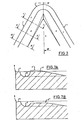
- the second embodiment of the cutting insert illustrated in Figure 3 includes a heel 7 having no lateral narrowing in the direction of the center of the insert, and thus defining a chip breaker groove 8 whose upper edges are parallel.
- FIG. 7A is also illustrated in dotted lines a first variant of the heel 7 ′, the upper level of which is situated above that of the cutting edge 1.
- FIG. 7B illustrates a second variant of the heel 7 "in which the upper level of it is below the level of cutting edge 1.
- the heel 7, respectively 7 ′ and 7 ′′ has a decreasing slope in the direction of the center of the pad, so as to create a rearward depression leaving the chips the freedom to evacuate and to fragment.
- the present invention brings on the one hand an increase in the field of use of the cutting insert and on the other hand a reduction in the power absorbed by this insert during the machining work.
- the increase in the field of use can be further extended if the decreasing heel according to the present invention is combined with a listel having a variable inclination passing from a positive or zero inclination on the nose or in the vicinity thereof. a zero or negative inclination along the cutting edge, as described in patent CH alone (request No ... of (19.5.81) in the name of the same holder.
Abstract
Description
La présente invention concerne des plaquettes de coupe pour usinage par enlèvement de copeaux comportant au moins une arête de coupe, un nez et un brise-copeaux. Ces plaquettes de coupe sont de préférence indexables et peuvent présenter une forme carrée, triangulaire, rhombique ou autre.The present invention relates to cutting inserts for machining by chip removal comprising at least one cutting edge, a nose and a chip breaker. These cutting inserts are preferably indexable and may have a square, triangular, rhombic or other shape.
Il est connu que les plaquettes utilisées pour la coupe, ou pour l'usinage par enlèvement de copeaux, de pièces métalliques ou autres, doivent être munies de brise-copeaux, exécutés généralement sous la forme de gorges ou rainures le long des arêtes de coupe, afin de favoriser le contrôle desdits copeaux. Toutefois, les exigences actuelles concernant le contrôle des copeaux et notamment leur fragmentation, pour faciliter d'une part l'évacuation desdits copeaux et pour augmenter d'autre part la sécurité d'emploi des outils, obligent à étudier les outils dans leur globalité, afin de satisfaire à ces exigences et, de plus, de diminuer la consommation d'énergie au cours du travail desdits outils. Il est également connu que ce brise-copeaux peut être de largeur variable et comporter dans sa section transversale une ou plusieurs parties, droites ou incurvées, variables en fonction de leur position le long de l'arête de coupe.It is known that the inserts used for cutting, or for machining by removing chips, metal parts or the like, must be provided with chip breakers, generally executed in the form of grooves or grooves along the cutting edges. , in order to favor the control of said chips. However, the current requirements concerning the control of chips and in particular their fragmentation, to facilitate on the one hand the evacuation of said chips and on the other hand to increase the safety of use of the tools, oblige to study the tools as a whole, in order to meet these requirements and, moreover, to reduce the energy consumption during the work of said tools. It is also known that this chipbreaker can be of variable width and comprise in its cross section one or more parts, straight or curved, variable according to their position along the cutting edge.
La gorge brise-copeaux présente généralement une remontée sur l'arrière, vers l'intérieur de la plaquette, au niveau de l'arête. Ceci est valable lorsqu'on se trouve dans un domaine de faibles profondeurs et de faibles avances, le copeau étant alors relativement mince et étroit. Le copeau va ainsi remonter le long de l'arrière de la gorge pour être brisé et rendre la plaquette utilisable dans cette zone. Dans le domaine des fortes profondeurs et fortes avances par contre, la section du copeau est importante et la remontée sur l'arrière mentionnée précédemment est un handicap, gênant le bon écoulement du copeau vers une fragmentation naturelle.The chip breaker groove generally has a rise on the rear, towards the inside of the insert, at the edge. This is valid when one is in a field of shallow depths and small advances, the chip then being relatively thin and narrow. The chip will thus go up along the back of the groove to be broken and make the plate usable in this area. In the area of great depths and strong advances on the other hand, the section of the chip is large and the ascent to the rear mentioned above is a handicap, hampering the good flow of the chip towards a natural fragmentation.
Le but de cette invention consiste par conséquent à obvier à l'inconvénient précité, en fournissant une plaquette de coupe du type mentionné précédemment dont la plage d'utilisation dans le domaine des fortes profondeurs de passe et des fortes avances soit augmentée.The object of this invention is therefore to obviate the aforementioned drawback, by providing a cutting insert of the type mentioned above, the range of use in the field of large depths of pass and strong advances is increased.
La plaquette de coupe pour usinage par enlèvement de copeaux selon l'invention comportant au moins une arête de coupe, un nez et un brise-copeaux formé par une gorge située le long de l'arête de coupe, et visant à atteindre le but ci-dessus, est caractérisée par le fait que la gorge brise-copeaux est délimitée vers l'intérieur de la plaquette par un talon, la hauteur de ce talon par rapport au fond de la gorge allant en décroissant à partir du nez et en direction du centre de la plaquette.The cutting insert for machining by chip removal according to the invention comprising at least one cutting edge, a nose and a chipbreaker formed by a groove located along the cutting edge, and aimed at achieving the aim ci above, is characterized by the fact that the chipbreaker groove is delimited towards the inside of the plate by a heel, the height of this heel relative to the bottom of the throat decreasing from the nose and in the direction of the center of the plate.
Le dessin annexé illustre schématiquement et à titre d'exemple l'invention.The accompanying drawing illustrates schematically and by way of example the invention.
- La figure 1 est une vue latérale partielle d'une première réalisation d'une plaquette de coupe selon l'invention.Figure 1 is a partial side view of a first embodiment of a cutting insert according to the invention.
- La figure 2 est une vue de dessus de la portion de plaquette illustrée sur la figure 1.FIG. 2 is a top view of the plate portion illustrated in FIG. 1.
- La figure 3 est une vue de dessus partielle d'une seconde réalisation d'une plaquette de coupe selon l'invention.Figure 3 is a partial top view of a second embodiment of a cutting insert according to the invention.
- Les figures 4 à 6 sont des vues en coupe selon les lignes I-I, II-II et III-III respectivement de la figure 3.Figures 4 to 6 are sectional views along lines I-I, II-II and III-III respectively of Figure 3.
- Les figures 7A et 7B sont des vues en coupe selon la ligne IV-IV de la figure 3 et sous la forme de deux autres variantes.Figures 7A and 7B are sectional views along the line IV-IV of Figure 3 and in the form of two other variants.
- La figure 8 représente une courbe en sac théorique.Figure 8 shows a theoretical bag curve.
- La figure 9 représente deux courbes en sac superposées obtenues respectivement pour une plaquette de coupe standard et pour une plaquette de coupe selon l'invention avec talon décroissant.FIG. 9 represents two superimposed bag curves obtained respectively for a standard cutting insert and for a cutting insert according to the invention with decreasing heel.
Le domaine d'utilisation d'une plaquette est défini par ce que l'on appelle une courbe en sac, qui est un domaine dans l'espace des profondeurs de passe, des avances et des vitesses, généralement mesuré à vitesse constante, à l'intérieur auquel la plaquette fragmente et controle le copeau correctement. Ce domaine, tel que défini sur la figure 8, peut être divisé en quatre sous-domaines principaux, chacun de ces sous-domaines étant contrôlé et généré principalement par une des parties de la plaquette.The field of use of a wafer is defined by what is called a bag curve, which is a field in the space of pass depths, feeds and speeds, generally measured at constant speed, at the interior at which the wafer fragments and controls the chip properly. This domain, as defined in FIG. 8, can be divided into four main sub-domains, each of these sub-domains being controlled and generated mainly by one of the parts of the brochure.
Le but mentionné précédemment de la présente invention consiste donc à élargir le domaine D de la courbe en sac.The previously mentioned object of the present invention therefore consists in widening the domain D of the bag curve.
Pour cela, il convient que, vers le milieu de l'arête de coupe, le copeau soit moins gêné, et par conséquent-que la hauteur du talon soit diminuée, voire annulée.For this, it is advisable that, towards the middle of the cutting edge, the chip is less hampered, and consequently that the height of the heel is reduced, or even canceled.
Sur les figures 1 et 2 est illustrée une partie d'une plaquette de coupe triangulaire indexable comportant une arête de coupe 1 présentant des portions rectilignes et une portion arrondie formant un nez ou bec 2, un brise-copeaux 3 et un listel 4 situé entre le brise-copeaux 3 et l'arête de coupe 1. En arrière du nez 2, en direction du centre de la plaquette constitué ici par un orifice traversant 5 destiné à recevoir un élément de fixation, est disposé un talon 6. La partie avant de ce talon 6, proche du nez 2, remonte depuis le fond de la gorge brise-copeaux 3 (voir figure 1) approximativement jusqu'au niveau de l'arête de coupe ou légèrement au-dessus, puis décroît vers l'arrière, c'est-à-dire vers le centre de la plaquette, selon une pente continue. Dans cette réalisation, le talon 6 présente également un rétrécissement latéral en direction du centre de la plaquette, de manière à dégager complètement celui-ci pour permettre l'évacuation et la fragmentation des copeaux.FIGS. 1 and 2 illustrate a part of an indexable triangular cutting insert comprising a cutting edge 1 having rectilinear portions and a rounded portion forming a nose or
La seconde réalisation de la plaquette de coupe illustrée à la figure 3 comporte un talon 7 ne présentant pas de rétrécissement latéral en direction du centre de la plaquette, et délimitant ainsi une gorge brise-copeaux 8 dont les rebords supérieurs sont parallèles.The second embodiment of the cutting insert illustrated in Figure 3 includes a
Les coupes selon les lignes I-I à IV-IV de la figure 3 illustrées respectivement sur les figures 4 à 7A montrent d'une part que la paroi du talon 7 délimitant la gorge 8 est relativement abrupte et d'autre part que vers le centre de l'arête de coupe 1 le talon 7 atteint une valeur nulle, c'est-à-dire rejoint le fond de la gorge brise-copeaux 8.The sections along lines II to IV-IV of Figure 3 illustrated respectively in Figures 4 to 7A show on the one hand that the wall of the
Sur la figure 7A est également illustrée en pointillé une première variante du talon 7' dont le niveau supérieur est situé au-dessus de celui de l'arête de coupe 1. La figure 7B illustre elle une seconde variante du talon 7" dans laquelle le niveau supérieur de celui-ci est au-dessous du niveau de l'arête de coupe 1.In FIG. 7A is also illustrated in dotted lines a first variant of the
Ainsi, le talon 7, respectivement 7' et 7", présente une pente décroissante en direction du centre de la plaquette, de manière à créer une dépression vers l'arrière laissant aux copeaux la liberté de s'évacuer et de se fragmenter.Thus, the
L'effet de ce talon décroissant est visible sur les courbes en sac réparties sur la figure 9 et obtenues avec une plaquette standard avec talon constant d'une part et avec un talon décroissant d'autre part. On peut en effet constater sur cette figure 9 que le resserrement du domaine D de la courbe en sac avec talon constant disparaît lorsque l'on passe à un talon variable. Il a en outre été constaté qu'avec la plaquette de coupe selon l'invention, avec talon décroissant vers le centre, les efforts de coupe sont inférieurs à ceux nécessaires avec un talon constant.The effect of this decreasing heel is visible on the bag curves distributed in FIG. 9 and obtained with a standard plate with a constant heel on the one hand and with a decreasing heel on the other hand. We can indeed see in this figure 9 that the tightening of the domain D of the bag curve with constant heel disappears when we switch to a variable heel. It has also been found that with the cutting insert according to the invention, with the heel decreasing towards the center, the cutting forces are lower than those necessary with a constant heel.
Ainsi, la présente invention apporte d'une part une augmentation du domaine d'utilisation de la plaquette de coupe et d'autre part une diminution de la puissance absorbée par cette plaquette au cours du travail d'usinage.Thus, the present invention brings on the one hand an increase in the field of use of the cutting insert and on the other hand a reduction in the power absorbed by this insert during the machining work.
L'augmentation du domaine d'utilisation peut encore être étendue si l'on combine le talon décroissant selon la présente invention avec un listel présentant une inclinaison variable passant d'une inclinaison positive ou nulle sur le nez ou à proximité de celui-ci à une inclinaison nulle ou négative le long de l'arête de coupe, comme décrit dans le brevet CH ..... (demande No...du (19.5.81) au nom de la même titulaire.The increase in the field of use can be further extended if the decreasing heel according to the present invention is combined with a listel having a variable inclination passing from a positive or zero inclination on the nose or in the vicinity thereof. a zero or negative inclination along the cutting edge, as described in patent CH ..... (request No ... of (19.5.81) in the name of the same holder.
Claims (5)
Priority Applications (1)
| Application Number | Priority Date | Filing Date | Title |
|---|---|---|---|
| AT82103582T ATE15983T1 (en) | 1981-05-19 | 1982-04-27 | INSERT FOR MACHINING. |
Applications Claiming Priority (2)
| Application Number | Priority Date | Filing Date | Title |
|---|---|---|---|
| CH3247/81 | 1981-05-19 | ||
| CH324781A CH642884A5 (en) | 1981-05-19 | 1981-05-19 | CUTTING INSERT FOR MACHINING BY CHIP REMOVAL. |
Publications (2)
| Publication Number | Publication Date |
|---|---|
| EP0066091A1 true EP0066091A1 (en) | 1982-12-08 |
| EP0066091B1 EP0066091B1 (en) | 1985-10-09 |
Family
ID=4251835
Family Applications (1)
| Application Number | Title | Priority Date | Filing Date |
|---|---|---|---|
| EP82103582A Expired EP0066091B1 (en) | 1981-05-19 | 1982-04-27 | Cutting insert for metal cutting |
Country Status (6)
| Country | Link |
|---|---|
| US (1) | US4720217A (en) |
| EP (1) | EP0066091B1 (en) |
| AT (1) | ATE15983T1 (en) |
| CH (1) | CH642884A5 (en) |
| DE (1) | DE3266762D1 (en) |
| ES (1) | ES264710Y (en) |
Cited By (7)
| Publication number | Priority date | Publication date | Assignee | Title |
|---|---|---|---|---|
| EP0168555A1 (en) * | 1984-06-28 | 1986-01-22 | Sumitomo Electric Industries Limited | Throwaway insert |
| EP0278083A1 (en) * | 1987-01-09 | 1988-08-17 | Nederlandse Hardmetaal Fabrieken B.V. | Cutting tool for metal cutting |
| WO1993008944A1 (en) * | 1991-11-05 | 1993-05-13 | Krupp Widia Gmbh | Cutting tool |
| WO1994012302A1 (en) * | 1992-11-21 | 1994-06-09 | Krupp Widia Gmbh | Cutting insert |
| DE4422312A1 (en) * | 1994-06-17 | 1995-12-21 | Krupp Widia Gmbh | Cutting insert |
| WO1996011763A1 (en) * | 1994-10-17 | 1996-04-25 | Widia Gmbh | Polygonal cutting insert |
| WO2015081353A1 (en) * | 2013-12-02 | 2015-06-11 | Ceratizit Austria Gesellschaft M.B.H. | Rotary machining cutting insert |
Families Citing this family (7)
| Publication number | Priority date | Publication date | Assignee | Title |
|---|---|---|---|---|
| JPH052244Y2 (en) * | 1989-08-31 | 1993-01-20 | ||
| EP1714720B1 (en) * | 2004-01-14 | 2011-05-18 | Sumitomo Electric Hardmetal Corp. | Throw-away tip |
| US8678717B2 (en) * | 2007-03-27 | 2014-03-25 | Kyocera Corporation | Cutting insert, cutting tool, and method of cutting work material using cutting tool |
| US8967920B2 (en) | 2011-09-13 | 2015-03-03 | Iscar, Ltd. | Cutting insert and chip-control arrangement therefor |
| JP6422081B2 (en) * | 2014-02-07 | 2018-11-14 | 株式会社タンガロイ | Cutting insert |
| US10286455B2 (en) * | 2014-09-05 | 2019-05-14 | Sumitomo Electric Hardmetal Corp. | Throw-away tip |
| CN116517475B (en) * | 2023-06-30 | 2023-10-03 | 西南石油大学 | Novel wear-resistant and anti-collision beak-shaped tooth multi-blade PDC drill bit |
Citations (4)
| Publication number | Priority date | Publication date | Assignee | Title |
|---|---|---|---|---|
| DE2231631A1 (en) * | 1971-06-29 | 1973-02-08 | Mitsubishi Metal Mining Co Ltd | CUTTING TOOL |
| DE2309443A1 (en) * | 1972-02-26 | 1973-09-13 | Sumitomo Electric Industries | DISPOSAL USE |
| GB2004477A (en) * | 1977-08-05 | 1979-04-04 | Sumitomo Electric Industries | Throw away insert |
| US4214846A (en) * | 1978-09-26 | 1980-07-29 | Fansteel Inc. | Heavy duty insert |
Family Cites Families (7)
| Publication number | Priority date | Publication date | Assignee | Title |
|---|---|---|---|---|
| US3883748A (en) * | 1967-06-29 | 1975-05-13 | Matsushita Electric Ind Co Ltd | Phosphor for thermoluminescent type radiation dosimeter |
| SE349759B (en) * | 1971-10-27 | 1972-10-09 | Sandvik Ab | |
| SE380751B (en) * | 1971-11-12 | 1975-11-17 | Seco Tools Ab | FRIENDS |
| SE361609B (en) * | 1973-01-08 | 1973-11-12 | Sandvik Ab | |
| US3947937A (en) * | 1973-11-16 | 1976-04-06 | Karl Hertel | Control groove in cutting elements for metal working tools |
| US3885281A (en) * | 1974-06-10 | 1975-05-27 | Iscar Ltd | Cutting insert with chip control |
| US4359300A (en) * | 1980-12-29 | 1982-11-16 | General Electric Co. | Cutting insert with improved chip control |
-
1981
- 1981-05-19 CH CH324781A patent/CH642884A5/en not_active IP Right Cessation
-
1982
- 1982-04-26 ES ES1982264710U patent/ES264710Y/en not_active Expired
- 1982-04-27 EP EP82103582A patent/EP0066091B1/en not_active Expired
- 1982-04-27 DE DE8282103582T patent/DE3266762D1/en not_active Expired
- 1982-04-27 AT AT82103582T patent/ATE15983T1/en active
- 1982-05-04 US US06/374,738 patent/US4720217A/en not_active Expired - Lifetime
Patent Citations (4)
| Publication number | Priority date | Publication date | Assignee | Title |
|---|---|---|---|---|
| DE2231631A1 (en) * | 1971-06-29 | 1973-02-08 | Mitsubishi Metal Mining Co Ltd | CUTTING TOOL |
| DE2309443A1 (en) * | 1972-02-26 | 1973-09-13 | Sumitomo Electric Industries | DISPOSAL USE |
| GB2004477A (en) * | 1977-08-05 | 1979-04-04 | Sumitomo Electric Industries | Throw away insert |
| US4214846A (en) * | 1978-09-26 | 1980-07-29 | Fansteel Inc. | Heavy duty insert |
Cited By (11)
| Publication number | Priority date | Publication date | Assignee | Title |
|---|---|---|---|---|
| EP0168555A1 (en) * | 1984-06-28 | 1986-01-22 | Sumitomo Electric Industries Limited | Throwaway insert |
| EP0278083A1 (en) * | 1987-01-09 | 1988-08-17 | Nederlandse Hardmetaal Fabrieken B.V. | Cutting tool for metal cutting |
| US4934879A (en) * | 1987-01-09 | 1990-06-19 | Nederlandse Hardmetaal Fabrieken B.V. | Cutting tool for chip cutting metal work |
| WO1993008944A1 (en) * | 1991-11-05 | 1993-05-13 | Krupp Widia Gmbh | Cutting tool |
| US5577867A (en) * | 1991-11-05 | 1996-11-26 | Widia Gmbh | Cutter insert |
| WO1994012302A1 (en) * | 1992-11-21 | 1994-06-09 | Krupp Widia Gmbh | Cutting insert |
| US5758994A (en) * | 1992-11-21 | 1998-06-02 | Widia Gmbh | Cutting insert |
| DE4422312A1 (en) * | 1994-06-17 | 1995-12-21 | Krupp Widia Gmbh | Cutting insert |
| US5839857A (en) * | 1994-06-17 | 1998-11-24 | Widia Gmbh | Cutting insert |
| WO1996011763A1 (en) * | 1994-10-17 | 1996-04-25 | Widia Gmbh | Polygonal cutting insert |
| WO2015081353A1 (en) * | 2013-12-02 | 2015-06-11 | Ceratizit Austria Gesellschaft M.B.H. | Rotary machining cutting insert |
Also Published As
| Publication number | Publication date |
|---|---|
| EP0066091B1 (en) | 1985-10-09 |
| ATE15983T1 (en) | 1985-10-15 |
| US4720217A (en) | 1988-01-19 |
| CH642884A5 (en) | 1984-05-15 |
| ES264710Y (en) | 1983-05-16 |
| DE3266762D1 (en) | 1985-11-14 |
| ES264710U (en) | 1982-11-16 |
Similar Documents
| Publication | Publication Date | Title |
|---|---|---|
| EP0066091B1 (en) | Cutting insert for metal cutting | |
| EP2434917B1 (en) | Improvement for a shoe, in particular for a sports shoe | |
| CH647438A5 (en) | CUT GRAIN. | |
| EP0800429B1 (en) | Cutting insert having a chipbreaker for thin chips | |
| SK155798A3 (en) | A cutting insert with a rounded corner | |
| LU83605A1 (en) | CUTTING INSERTION | |
| US5249894A (en) | High sheer, ultra light duty insert | |
| AU5578499A (en) | Flat bottom tool | |
| CA2121427A1 (en) | Movable Blade Shaving Cartridge or the Like | |
| US5193948A (en) | Chip control inserts with diamond segments | |
| CA2151763A1 (en) | Cutting Insert | |
| EP1334653B1 (en) | Secateurs | |
| EP0065124B1 (en) | Cutting insert for metal cutting | |
| IL108408A0 (en) | Cutting insert | |
| FR2690892A1 (en) | Icebreaker ship. | |
| FR2779366A1 (en) | Drill bit with multi-cutting edges | |
| FR2481168A3 (en) | SUPPORT FOR INSERTED, INSERTED CUTTING INSERTS, AND INSERTS FOR SAID SUPPORT | |
| US6341924B1 (en) | Insert for the cutting of grooves | |
| CH631923A5 (en) | PNEUMATIC. | |
| FR2571330A1 (en) | Improved ship's hull | |
| CH651769A5 (en) | CUT GRAIN. | |
| EP0108004B1 (en) | Catamaran-type boat | |
| JP2585715Y2 (en) | Indexable tip | |
| EP0066079A1 (en) | Boring and slotting milling cutter | |
| EP0730925B1 (en) | High speed cutting insert with improved chip groove |
Legal Events
| Date | Code | Title | Description |
|---|---|---|---|
| PUAI | Public reference made under article 153(3) epc to a published international application that has entered the european phase |
Free format text: ORIGINAL CODE: 0009012 |
|
| AK | Designated contracting states |
Designated state(s): AT BE DE FR GB IT LU NL SE |
|
| 17P | Request for examination filed |
Effective date: 19830527 |
|
| ITF | It: translation for a ep patent filed |
Owner name: CON LOR S.R.L. |
|
| GRAA | (expected) grant |
Free format text: ORIGINAL CODE: 0009210 |
|
| AK | Designated contracting states |
Designated state(s): AT BE DE FR GB IT LU NL SE |
|
| REF | Corresponds to: |
Ref document number: 15983 Country of ref document: AT Date of ref document: 19851015 Kind code of ref document: T |
|
| REF | Corresponds to: |
Ref document number: 3266762 Country of ref document: DE Date of ref document: 19851114 |
|
| PLBE | No opposition filed within time limit |
Free format text: ORIGINAL CODE: 0009261 |
|
| STAA | Information on the status of an ep patent application or granted ep patent |
Free format text: STATUS: NO OPPOSITION FILED WITHIN TIME LIMIT |
|
| 26N | No opposition filed | ||
| ITTA | It: last paid annual fee | ||
| PGFP | Annual fee paid to national office [announced via postgrant information from national office to epo] |
Ref country code: LU Payment date: 19930324 Year of fee payment: 12 |
|
| PGFP | Annual fee paid to national office [announced via postgrant information from national office to epo] |
Ref country code: BE Payment date: 19930329 Year of fee payment: 12 |
|
| PGFP | Annual fee paid to national office [announced via postgrant information from national office to epo] |
Ref country code: SE Payment date: 19930330 Year of fee payment: 12 |
|
| PGFP | Annual fee paid to national office [announced via postgrant information from national office to epo] |
Ref country code: GB Payment date: 19930426 Year of fee payment: 12 |
|
| PGFP | Annual fee paid to national office [announced via postgrant information from national office to epo] |
Ref country code: AT Payment date: 19930427 Year of fee payment: 12 |
|
| PGFP | Annual fee paid to national office [announced via postgrant information from national office to epo] |
Ref country code: NL Payment date: 19930430 Year of fee payment: 12 Ref country code: FR Payment date: 19930430 Year of fee payment: 12 |
|
| PGFP | Annual fee paid to national office [announced via postgrant information from national office to epo] |
Ref country code: DE Payment date: 19930629 Year of fee payment: 12 |
|
| EPTA | Lu: last paid annual fee | ||
| PG25 | Lapsed in a contracting state [announced via postgrant information from national office to epo] |
Ref country code: LU Free format text: LAPSE BECAUSE OF NON-PAYMENT OF DUE FEES Effective date: 19940427 Ref country code: GB Effective date: 19940427 Ref country code: AT Effective date: 19940427 |
|
| PG25 | Lapsed in a contracting state [announced via postgrant information from national office to epo] |
Ref country code: SE Effective date: 19940428 |
|
| PG25 | Lapsed in a contracting state [announced via postgrant information from national office to epo] |
Ref country code: BE Effective date: 19940430 |
|
| BERE | Be: lapsed |
Owner name: STELLRAM S.A. Effective date: 19940430 |
|
| PG25 | Lapsed in a contracting state [announced via postgrant information from national office to epo] |
Ref country code: NL Effective date: 19941101 |
|
| NLV4 | Nl: lapsed or anulled due to non-payment of the annual fee | ||
| GBPC | Gb: european patent ceased through non-payment of renewal fee |
Effective date: 19940427 |
|
| PG25 | Lapsed in a contracting state [announced via postgrant information from national office to epo] |
Ref country code: FR Effective date: 19941229 |
|
| PG25 | Lapsed in a contracting state [announced via postgrant information from national office to epo] |
Ref country code: DE Effective date: 19950103 |
|
| EUG | Se: european patent has lapsed |
Ref document number: 82103582.1 Effective date: 19941110 |
|
| REG | Reference to a national code |
Ref country code: FR Ref legal event code: ST |