EP0066067B1 - Video recorder by which multiple sound carriers and a picture carrier are recorded on a recording-track - Google Patents
Video recorder by which multiple sound carriers and a picture carrier are recorded on a recording-track Download PDFInfo
- Publication number
- EP0066067B1 EP0066067B1 EP82103094A EP82103094A EP0066067B1 EP 0066067 B1 EP0066067 B1 EP 0066067B1 EP 82103094 A EP82103094 A EP 82103094A EP 82103094 A EP82103094 A EP 82103094A EP 0066067 B1 EP0066067 B1 EP 0066067B1
- Authority
- EP
- European Patent Office
- Prior art keywords
- frequency
- sound
- carrier
- recorder according
- signal
- Prior art date
- Legal status (The legal status is an assumption and is not a legal conclusion. Google has not performed a legal analysis and makes no representation as to the accuracy of the status listed.)
- Expired
Links
Images


Classifications
-
- H—ELECTRICITY
- H04—ELECTRIC COMMUNICATION TECHNIQUE
- H04N—PICTORIAL COMMUNICATION, e.g. TELEVISION
- H04N9/00—Details of colour television systems
- H04N9/79—Processing of colour television signals in connection with recording
- H04N9/80—Transformation of the television signal for recording, e.g. modulation, frequency changing; Inverse transformation for playback
- H04N9/82—Transformation of the television signal for recording, e.g. modulation, frequency changing; Inverse transformation for playback the individual colour picture signal components being recorded simultaneously only
- H04N9/83—Transformation of the television signal for recording, e.g. modulation, frequency changing; Inverse transformation for playback the individual colour picture signal components being recorded simultaneously only the recorded chrominance signal occupying a frequency band under the frequency band of the recorded brightness signal
- H04N9/835—Transformation of the television signal for recording, e.g. modulation, frequency changing; Inverse transformation for playback the individual colour picture signal components being recorded simultaneously only the recorded chrominance signal occupying a frequency band under the frequency band of the recorded brightness signal involving processing of the sound signal
- H04N9/8355—Transformation of the television signal for recording, e.g. modulation, frequency changing; Inverse transformation for playback the individual colour picture signal components being recorded simultaneously only the recorded chrominance signal occupying a frequency band under the frequency band of the recorded brightness signal involving processing of the sound signal the sound carriers being frequency multiplexed between the luminance carrier and the chrominance carrier
Definitions
- the sound signal is recorded and scanned on a longitudinal track running parallel to the edge of the tape and having a width of about 1 mm with a fixed head.
- Decisive for the recording and scanning of the sound signal is the lower longitudinal speed of the tape and not the much higher relative speed between head and tape on the helical tracks.
- the length of the tape has now been reduced in practice to increase the total playing time of a tape to values of the order of 2 cm / s.
- This low relative speed between the tape and the tape head has an adverse effect on the quality of the recorded audio signal. Hi-fi quality can practically no longer be achieved at this low relative speed.
- the recorded sound signal only has a bandwidth of about 70 Hz to max. 10 kHz. Because of the narrow width of the longitudinal track, there is also a relatively poor signal-to-noise ratio. This becomes even worse when two audio signals are recorded for stereo playback or bilingual playback due to the need to halve the width of the longitudinal track.
- the processing of the sound signals causes additional circuitry expenditure and a reduction in quality, in particular a reduction in the signal-to-noise ratio.
- the invention has for its object to form a video recorder with the recording of two modulated sound carriers together with the modulated image carrier on a recording track so that the two sound carriers of a standardized television signal with their standardized frequency spacing can be obtained with little circuitry and low quality degradation during playback.
- VHF quality for the sound can be achieved by high-frequency recording of the sound signal and the saving of any demodulation and new modulation.
- Another advantage is that the longitudinal track previously required for recording the sound signal can be omitted.
- An additional area of the magnetic tape can then be used for the recording of the image signal, or this area can also be used. This can either improve the quality of the image recording or reduce the tape consumption.
- a particularly good utilization of the magnetic tape can be achieved if, according to DE-A-30 11 635, the previously used synchronous track parallel to the tape edge for marking the inclined tracks is also saved and the signal required for the head control, indicating the individual inclined tracks, with a fixed head from the Inclined traces are derived using the so-called azimuth angle.
- a video recorder can only be used with rotating heads for writing the helical tracks, i.e. without additional recording heads for longitudinal tracks such as B. for sound recording or dubbing.
- the tape area freed up in this way enables the playing time to be increased by approximately 16% with the same image quality and the same tape length. With a cassette designed for a playing time of 4 hours, this means an additional playing time of 40 minutes.
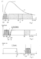
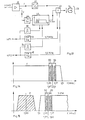
- the frequency-reduced quadrature-modulated color carrier F is recorded in the lower frequency range with a frequency of 0.63 MHz and a bandwidth of approximately ⁇ 500 kHz.
- the video signal V is recorded by FM of an image carrier. Its static modulation characteristic extends between the frequencies 3.8 and 4.8 MHz, where 3.8 MHz corresponds to the ultra black level and 4.8 MHz to the white level of the video signal. The modulation results in a frequency spectrum of 1.3 to 7.3 MHz. Due to the head gap, the upper sideband (above 6 MHz) is not scanned completely, so that interference from signal reflections is reduced. Sound signals are not included in the known spectrum. They are prepared separately in known devices and recorded in a track running along the band edge.
- the two luminance and chrominance signal spectra are shown enlarged in FIG. 2, the position of the sound signals introduced by the invention being indicated.
- two sound carriers 1 and 2 each modulated with an LF sound signal in FM, are recorded at the frequencies 1.07 and 1.31 MHz. If a stereo signal is introduced on the transmitter side, which has a spacing of the FM sound carriers of 250 kHz, then the carriers 1, 2 should also have a corresponding spacing for the purpose of simple implementation which is favorable for quality improvement.
- the two LF audio signals can represent a mono signal, a stereo signal or a sound signal in different languages.
- the frequencies of the two sound carriers 1, 2 are approximately at the maximum 4 of the head-band frequency response characteristic 5, which is effective when recording the entire signal on the helical tracks.
- FIG. 3 shows in the normal frequency spectrum of the television signal the bandwidth losses of the luminance signal and of the chrominance signal introduced by the invention.
- the loss of the chrominance signal at D is 0.06 MHz.
- the loss of the luminance signal is 0.10 MHz.
- the loss of resolution of the luminance signal is ver negligible and the single sideband error of the chrominance signal not noticeable.
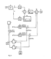
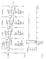
- the CVBS signal in the circuit 6 is separated by frequency-selective means into the modulated color carrier F and the luminance signal Y (luminance signal).
- the modulated PAL color carrier F (chrominance signal) is converted in the frequency converter 7 from its original frequency 4.43 MHz to the frequency 0.63 MHz and via a notch filter N1, which is a filter with an extremely steep edge for shifting the upper edge of the chrominance band, the adder 8 fed.
- the luminance signal Y is modulated onto an image carrier in the frequency modulator 9, as a result of which a frequency spectrum of 1.3 to 7.3 MHz according to FIG. 1 is produced. In this frequency spectrum, the lower edge of the luminance band is shifted upward in the circuit 10 by a notch filter, not shown.
- the signal remaining as a result is also fed to the adder 8.
- Two sound signals NF1 and NF2, e.g. B. from a microphone input two carriers with the frequency of 1.07 and 1.31 MHz are modulated in two frequency modulators 11, 12, which are also supplied to the adder 8.
- an FM hub of ⁇ 50 kHz is selected, which results in modulation bandwidths of 1.07 or 1.31 MHz ⁇ 70 kHz.
- the frequencies of the two sound carriers according to FIG. 2 are suppressed in the circuit 10 by the notch filter mentioned.
- the output signal of the adder 8 contains the signals shown in FIG.
- Mixers or modulators M1 and M2 are provided for recording sound signals, such as those broadcast by television stations and received by a tuner T, which mix the received modulated sound carriers 1 and convert them to intermediate frequencies ZF1 (5.5 MHz) and ZF2 (5.742 MHz) , 2 implement while maintaining the high frequency to frequencies of 1.07 and 1.31 MHz.
- a quartz-stabilized reference frequency source R is provided with a frequency of 4.43 MHz, which can be the color carrier reference oscillator already present in PAL devices.
- the IC MM 1496 (Motorola) has proven itself as a mixer.
- the output terminals of the mixers M1 and M2 are connected to the adder via switches S1 and S2, so that the device can optionally be switched to the LF audio signal and the RF audio signal.
- the source R can also be a separate oscillator.
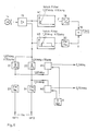
- FIG. 5 shows a modification of FIG. 4.
- the difference lies in the use of a single notch filter N for chrominance and luminance channels, which is shown in detail in FIG. 10.
- the output signals of the frequency converter 7 and the filter circuit 10 are fed to an adder 8, to which, in contrast to FIG. 4, the sound signals are not fed.
- the output of the adder 8 is fed to the notch filter N and from there to another adder 8a, to which the sound signals from the switches S1 and S2 are also fed.
- FIG. 6 shows a circuit for reproducing the recorded spectrum according to FIG. 2.
- the signal sampled alternately by the heads 14a, 14b is amplified in an amplifier 15 and split into the chrominance channel and the luminance channel with separate notch filters N1 and N2.
- Demodulators 18 and 20 demodulate these signals and pass the demodulated signals to an adder circuit 19, in which the CVBS signal is recovered. Further processing takes place in the usual, known manner.
- the sound signal is split off in front of the inputs of the notch filters N1, N2 and fed via filters 21, 22 to two mixers M1, M2, which recover the sound IF signals Tone ZF1, Tone ZF2 by means of the reference frequency of the source R.
- These IF signals can be fed to the receiver directly or via renewed conversion into the reception channels of the VHF / UHF band.
- the sampled audio signals can also be demodulated directly if this is required in the recorder.
- the signal mixture according to FIG. 1, which is alternately sampled by the heads 14a, 14b, is amplified in the amplifiers 15a and 15b and freed of the audio signal via the notch filter N and via filters 16, 17 in the modulated color carrier F and split the modulated image carrier Y Fm . Since the change between the heads 14a, 14b takes place during the duration of the vertical blanking interval, no additional measures with regard to the video signals are required, apart from a hard electronic switch 27 for the head signals of the amplifier outputs 15a and 15b for a correct color conversion and FM demodulation. The color carrier F is converted back to the frequency of 4.43 MHz in the frequency converter 18 and fed to the adder 19.
- the luminance signal Y is obtained in the frequency demodulator 20 and supplied to the adder 19.
- the overall signal mix provided by heads 14a and 14b has overlap zones in which both heads 14a, 14b are in contact with the tape and deliver output signals. These overlapping zones form a soft electronic cross-fading device for the sound carrier signals.
- the entire signal mixture supplied by the heads 14a, 14b is branched off before any circuit for linearizing the envelope curve of the video signal mixture supplied by the heads or before any device for hard electronic cross-fading.
- the two modulated sound carriers are selectively separated from the signal mixture according to FIG. 2 using narrow-band filters 21, 22 and fed to mixers M1, M2.
- the mixers deliver the two tone signals tone ZF1 and tone ZF2.
- the total signal supplied by the head 14a or by the amplifier 15a is fed to an adder 25 before being fed to the demodulators 23, 24.
- the total signal supplied by the head 14b or by the amplifier 15b is fed to an amplifier 26, the output signal of which is also fed to the adder 25.
- the output signal of the adder now has a signal with a sound signal component even during the switchover phase of the heads, so that the otherwise inevitable 50 Hz interference cannot occur.
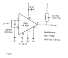
- FIG. 9 shows an example which is suitable as a filter 21, 22 and at the same time as an amplifier for the FM tone IF signals.
- a component can, for. B. can be realized using the RCA broadband amplifier IC's CA 3011.
- frequencies for sound carriers and reference carriers are given as examples. In practice, depending on the type of application, both the exact values specified in the standard and simplified values (e.g. 5.742 187 5 MHz or only 5.74 MHz for the audio signal NF2) can be used.
- a quartz-stabilized PAL reference oscillator with a frequency of 4.433 618 MHz ⁇ 1 kHz was used as the reference carrier source R, but in most cases the accuracy can be set to be lower than that for decoding of the PAL signals is required. The accuracy must be so great that the demodulation takes place in the linear range of the demodulator characteristic.
- the CVBS signal is fed to amplifier 41.
- This delivers the modulated PAL color carrier F with a frequency of 4.43 MHz. This frequency is reduced in the frequency converter 42 to a frequency of 0.63 MHz.
- the color carrier which is thus reduced in frequency, is fed to the adder 43.
- the amplifier 41 also supplies the luminance signal Y, which is modulated onto an image carrier in the frequency modulator 44. This arrives at the filter 45, which passes the frequency spectrum at the output of the modulator 44, but has two blocking points therein at the frequencies 1.7 and 1.9 MHz.
- the image carrier Y-FM frequency-modulated with the Y signal is also fed to the adder 43.
- a first sound signal NF1 is fed to the FM modulator 46, which generates a first sound carrier with the frequency of 1.7 MHz.
- a second sound signal NF2 is fed to the second FM modulator 47, which generates a second sound carrier with the frequency of 1.9 MHz.
- the two sound carriers are also fed to the adder 43.
- This signal is fed to the video head 14 and recorded on the magnetic tape 28. In practice there are generally two video heads which record fields one after the other on inclined tracks 29 of the magnetic tape 28.
- Signal NF1 is also fed to flip-flop 50 with a threshold characteristic. If the instantaneous value of the signal NF1 exceeds a certain value, a manipulated variable arises at the output of the stage 50, which increases the blocking bandwidth at the frequency of 1.7 MHz in the filter 45. The frequency range which is suppressed in the filter 45 at the frequency of 1.7 MHz thus becomes the respective amplitude of the signal NF1 adjusted. In the same way, the sound signal NF2 is fed to stage 51. Their output voltage controls the bandwidth of the suppression in the filter 45 at the frequency of 1.9 MHz.
- FIG. 14 shows the blocking bandwidth 52 for the sound carrier at 1.7 MHz and the blocking bandwidth 53 for the sound carrier at 1.9 MHz, in relation to the base frequency band of the Y signal.
- the controllable filter would then lie in the path of the Y signal, that is to say in front of the modulator 44, so that the frequency components do not arise in the region of the two sound carriers during modulation in the modulator 44.
- the blocking bandwidths 52, 53 shown are therefore not constant, but are dependent on the respective amplitude of the audio signals NF1 and NF2.
- FIG. 15 shows the frequency carrier F which is reduced in frequency and the frequency spectrum of the modulated image carrier Y-FM at the output of the filter 45.
- the blocking bandwidths 52, 53 shown with the frequencies shown thus apply to the maximum amplitude of the audio signals NF1, NF2 and become lower as the frequency decreases Amplitude reduced accordingly.
- the static modulation characteristic of the modulator 44, which effects the frequency spectrum according to FIG. 15, lies between the frequencies 3.8 MHz for the black level and 4.8 MHz for the white level of the video signal Y.
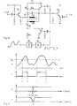
- FIG. 16 shows an example of a circuit for the controllable filter 45 in FIG. 13.
- the signal Y-FM is fed via the emitter follower transistor stage 54 to the resonant circuit 55, which is tuned to the frequency of 1.7 MHz or 1.9 MHz, and is supplied via another Emitter follower stage 56 is connected to the output terminal leading to adder 43.
- the inductance of the blocking circuit 55 consists of the two mutually identical windings 57, 58, which are designed as a bifilar winding.
- the connection point of the windings 57, 58, i.e. H. the center tap of the inductance of the blocking circuit is connected to earth via the adjustable resistor 59 and the resistor 60.
- Transistor 61 is connected in parallel with resistor 60.
- the resistor 62 and a further resistor 63 are also connected in parallel with the resonant circuit 55 via the transistor 64.
- the control of the filter according to FIG. 16 is explained with reference to FIG. 17. If the sound signal NF1 according to FIG. 17a lies below the threshold value U s , the transistors 61, 64 are blocked. The resistor 63 is then ineffective for damping the resonant circuit 55. The resistor 60 is not bridged, so that the connection point of the windings 57, 58 is grounded at high resistance. The filter now has its minimum blocking bandwidth at 1.7 MHz according to FIG. 17c.
- the flip-flop 65 is triggered and generates a pulse according to FIG. 17b, which reaches the bases of the transistors 61, 64 via the amplifier 66.
- the transistor 61 then bridges the resistor 60, so that the connection point of the windings 57, 58 is now grounded via the resistor 59 with low resistance.
- the transistor 64 also becomes conductive and switches the resistor 63 in parallel with the blocking circuit, so that its damping is increased. This stronger damping of the blocking circuit 55 results in an enlarged blocking bandwidth according to FIG. 17d, which is adapted to the larger amplitude of the signal NF1.
- the blocking bandwidth 53 is controlled in the same way with a further filter according to FIG. 17, only for the other frequency of 1.9 MHz.
- the blocking bandwidth is switched between two values according to FIGS. 17c and 17d. Continuous control of the blocking bandwidths 52, 53 by the amplitude of the sound signal NF1 or NF2 is also possible. It is also possible to supply the sound signal to a rectifier or a filter element, to obtain a manipulated variable obtained from the mean amplitude and to use this manipulated variable to control the blocking bandwidth 52 or 53.
Description
Bei Videorecordern ist es bekannt, das Videosignal durch Frequenzmodulation eines Bildträgers auf sogenannten Schrägspuren aufzuzeichnen, die unter einem vorbestimmten Winkel (bei VHS-Geräten ca. 6°) schräg zur Längsrichtung des Bandes verlaufen. Dabei ist vorzugsweise entlang einer derartigen Schrägspur jeweils z. B. ein Halbbild aufgezeichnet. Aufzeichnung und Abtastung erfolgen mit rotierenden Köpfen (bei VHS zwei Köpfe), die jeweils abwechselnd mit den Schrägspuren Kontakt haben. Auf diese Weise wird bei relativ langsamer Bandgeschwindigkeit die für Videoaufzeichnung erforderliche hohe Relativgeschwindigkeit zwischen Kopf und Band erreicht.In video recorders it is known to record the video signal by means of frequency modulation of an image carrier on so-called inclined tracks which run obliquely to the longitudinal direction of the tape at a predetermined angle (approx. 6 ° in the case of VHS devices). It is preferably along such a helical track z. B. recorded a field. Recording and scanning are carried out with rotating heads (two heads for VHS), which alternately have contact with the inclined tracks. In this way, the high relative speed between head and tape required for video recording is achieved at a relatively slow tape speed.
Bei derartigen Geräten wird das Tonsignal auf einer parallel zur Bandkante verlaufenden Längsspur mit einer Breite von etwa 1 mm mit einem feststehenden Kopf aufgezeichnet und abgetastet. Für die Aufzeichnung und Abtastung des Tonsignals ist also die kleinere Längsgeschwindigkeit des Bandes und nicht die wesentlich höhere Relativgeschwindigkeit zwischen Kopf und Band auf den Schrägspuren entscheidend. Die Längsgeschwindigkeit des Bandes ist nun in der Praxis zur Vergrößerung der Gesamtspieldauer eines Bandes auf Werte in der Größenordnung von 2 cm/s verringert worden. Diese geringe Relativgeschwindigkeit zwischen dem Band und dem Tonkopf hat einen nachteiligen Einfluß auf die Qualität des aufgezeichneten Tonsignals. Eine Hifi-Qualität läßt sich bei dieser geringen Relativgeschwindigkeit praktisch nicht mehr erreichen. Das aufgezeichnete Tonsignal hat nur noch eine Brandbreite von etwa 70 Hz bis max. 10 kHz. Wegen der geringen Breite der Längsspur ergibt sich auch ein relativ schlechter Störabstand. Dieser wird bei der Aufzeichnung von zwei Tonsignalen für Stereo-Wiedergabe oder Zweisprachen-Wiedergabe durch die dann notwendige Halbierung der Breite der Längsspur noch schlechter.In such devices, the sound signal is recorded and scanned on a longitudinal track running parallel to the edge of the tape and having a width of about 1 mm with a fixed head. Decisive for the recording and scanning of the sound signal is the lower longitudinal speed of the tape and not the much higher relative speed between head and tape on the helical tracks. The length of the tape has now been reduced in practice to increase the total playing time of a tape to values of the order of 2 cm / s. This low relative speed between the tape and the tape head has an adverse effect on the quality of the recorded audio signal. Hi-fi quality can practically no longer be achieved at this low relative speed. The recorded sound signal only has a bandwidth of about 70 Hz to max. 10 kHz. Because of the narrow width of the longitudinal track, there is also a relatively poor signal-to-noise ratio. This becomes even worse when two audio signals are recorded for stereo playback or bilingual playback due to the need to halve the width of the longitudinal track.
Es ist bekannt (DE-B-12 77 900), bei einer Schrägspuraufzeichnung einen oder mehrere mit Tonsignalen modulierte Tonträger zusammen mit dem Bildträger auf den Schrägspuren aufzuzeichnen. Dabei wird die Frequenz der Tonträger soweit herabgesetzt, daß sie unterhalb des vom modulierten Bildträger eingenommenen Frequenzspektrums liegt. Diese Lösung hat den Vorteil, daß wegen der hohen Relativgeschwindigkeit zwischen den Videoköpfen und dem Magnetband entlang den Schrägspuren auch für die Tonsignale eine hohe Aufzeichnungsbandbreite und somit eine hohe Tonqualität erreicht werden.It is known (DE-B-12 77 900) to record one or more sound carriers modulated with sound signals together with the image carrier on the helical tracks in a helical track recording. The frequency of the sound carriers is reduced to such an extent that it lies below the frequency spectrum occupied by the modulated image carrier. This solution has the advantage that, because of the high relative speed between the video heads and the magnetic tape along the inclined tracks, a high recording bandwidth and thus a high sound quality are also achieved for the sound signals.
Bei einer derartigen Aufzeichnung entsteht jedoch bei der Tonwiedergabe eine Störung durch den Kopfwechsel bei Übergang von einer Schrägspur auf die nächste, weil die Abtastung vom Band kurzzeitig unterbrochen ist und Phasensprünge im Tonträger auftreten, die nach einer FM-Demodulation hörbare Störimpulse erzeugen.In such a recording, however, there is a disturbance in the sound reproduction due to the head change when changing from one helical track to the next, because the scanning from the tape is briefly interrupted and phase jumps occur in the sound carrier, which produce audible interference pulses after FM demodulation.
Es wurde bereits vorgeschlagen (EP-A1 0 061 050), bei der Wiedergabe die Ausgangssignale der beiden rotierenden Köpfe im Tonsignalweg so unterschiedlich zu verstärken, daß die Tonträger auch bei Addition oder Subtraktion im Überlappungsbereich einander nicht auslöschen können und somit ein kontinuierlicher ununterbrochener Tonträger verfügbar ist.It has already been proposed (EP-A1 0 061 050) to amplify the output signals of the two rotating heads in the audio signal path so differently during playback that the audio carriers cannot cancel one another even when added or subtracted in the overlap area and thus a continuous, uninterrupted audio carrier is available is.
Bei der beschriebenen Art der Tonaufzeichnung bewirkt die Aufbereitung der Tonsignale, insbesondere die Herabsetzung der Tonträgerfrequenzen bei der Aufnahme und die Hochsetzung bei der Wiedergabe, einen zusätzlichen Schaltungsaufwand sowie eine Qualitätsminderung, insbesondere eine Verringerung des Störabstandes.In the type of sound recording described, the processing of the sound signals, in particular the reduction of the sound carrier frequencies when recording and the step-up during playback, causes additional circuitry expenditure and a reduction in quality, in particular a reduction in the signal-to-noise ratio.
Der Erfindung liegt die Aufgabe zugrunde, einen Videorecorder mit Aufzeichnung von zwei modulierten Tonträgern zusammen mit dem modulierten Bildträger auf einer Aufzeichnungsspur so auszubilden, daß bei geringem Schaltungsaufwand und geringer Qualitätsminderung bei der Wiedergabe die beiden Tonträger eines genormten Fernsehsignals mit ihrem genormten Frequenzabstand gewonnen werden können.The invention has for its object to form a video recorder with the recording of two modulated sound carriers together with the modulated image carrier on a recording track so that the two sound carriers of a standardized television signal with their standardized frequency spacing can be obtained with little circuitry and low quality degradation during playback.
Diese Aufgabe wird durch die im Anspruch 1 beschriebene Erfindung gelöst. Vorteilhafte Weiterbildungen der Erfindung sind in den Unteransprüchen beschrieben.This object is achieved by the invention described in
Es ist zwar bekannt (DE-A-22 01 691 bei der Aufzeichnung des Farbträgers, des Tonträgers und des Bildträgers auf einer Spur eines Aufzeichnungsträgers den Farbträger und den Tonträger mit einem Pilotträger so zu mischen, daß ein in der Frequenz herabgesetzter Farbträger und unterhalb dessen Frequenzspektrum ein in der Frequenz herabgesetzter Tonträger entstehen. Diese Träger werden aufgezeichnet und der Tonträger bei Wiedergabe wieder in seine Original-Frequenzlage umgesetzt. Dort wird jedoch nicht die Aufzeichnung von zwei frequenzmodulierten Tonträgern behandelt. Es werden daher auch nicht zwei Tonträger mit herabgesetzten Frequenzen und einem der Norm entsprechenden Frequenzabstand erzeugt, mit diesen Frequenzabstand aufgezeichnet und bei der Wiedergabe unter Beibehaltung des Frequenzabstandes wieder in der Frequenz hochgesetzt.It is known (DE-A-22 01 691 when recording the color carrier, the sound carrier and the image carrier on a track of a recording medium to mix the color carrier and the sound carrier with a pilot carrier so that a frequency carrier reduced in frequency and below it These recordings are recorded and the recordings are converted back to their original frequency position when they are played back. However, the recording of two frequency-modulated recordings is not dealt with there. Therefore, two recordings with reduced frequencies and one are not treated generated the frequency spacing corresponding to the standard, recorded with this frequency spacing and increased in frequency again during playback while maintaining the frequency spacing.
Die bei der Erfindung vorgenommene Verringerung des oberen Seitenbandes des Farbträgers durch Bandbeschneidung ergibt zwar theoretisch Fehler, doch hat sich gezeigt, daß diese Fehler im wiedergegebenem Bild praktisch nicht merkbar sind. Bei PAL-Empfängern kompensiert das Prinzip des Farbfernsehsystem solche Fehler. Auch bei NTSC und SECAM ist dieser Fehler nicht so groß, das er im Bild störend wirkt.The reduction of the upper side band of the ink carrier by means of band trimming made in the invention results in errors in theory, but it has been shown that these errors are practically imperceptible in the reproduced image. The principle of the color television system compensates for such errors in PAL receivers. Even with NTSC and SECAM, this error is not so great that it has a disturbing effect in the picture.
Durch die Anwendung der bekannten Aufzeichnung der Tonträger gemeinsam mit dem Bildträger entlang derselben Aufzeichnungsspur zusammen mit der erfindungsgemäßen Lösung ergeben sich im wesentlichen folgende Vorteile :
- Qualität der Original-Ton-Sendung bleibt erhalten. Auf eine FM-Tonträgerdemodulation für die Aufnahme kann verzichtet werden. Auf ein Kompandersystem kann verzichtet werden. Auf ein automatische Aussteuerung kann verzichtet werden. Auf die Generierung eines neuen Pilotsignals kann verzichtet werden. Auf den gesonderten Tonkopf kann verzichtet werden.
- The quality of the original sound broadcast is preserved. There is no need for FM sound carrier demodulation for recording. There is no need for a compander system. An automatic control is not necessary. There is no need to generate a new pilot signal. The separate sound head can be dispensed with.
Durch hochfrequenzmäßige Aufzeichnung des Tonsignals und die Einsparung jeglicher Demodulation und Neumodulation läßt sich eine UKW-Qualität für den Ton erreichen. Ein weiterer Vorteil besteht darin, daß die bisher benötigte Längsspur für die Aufzeichnung des Tonsignals entfallen kann. Es kann dann entweder ein zusätzlicher Bereich des Magnetbandes für die Aufzeichnung des Bildsignals verwendet werden, oder dieser Bereich kann zusätzlich genutzt werden. Dadurch kann entweder die Qualität der Bildaufzeichnung verbessert oder der Bandverbrauch verringert werden. Eine besonders gute Ausnutzung des Magnetbandes läßt sich erreichen, wenn gemäß der DE-A-30 11 635 zusätzlich die bisher verwendete Synchronspur parallel zur Bandkante zur Markierung der Schrägspuren eingespart und das zur Kopfregelung benötigte, die einzelnen Schrägspuren anzeigende Signal mit einem feststehenden Kopf aus den Schrägspuren unter Ausnutzung des sogenannten Azimutwinkels abgeleitet wird. Dadurch läßt sich ein Videorecorder nur mit rotierenden Köpfen für das Schreiben der Schrägspuren, also ohne zusätzliche Aufzeichnungsköpfe für Längsspuren wie z. B. für die Tonaufzeichnung oder die Synchronspur, verwirklichen. Die dadurch frei werdende Bandfläche ermöglicht bei gleicher Bildqualität und gleicher Bandlänge eine Erhöhung der Spielzeit um etwa 16 %. Das bedeutet bei einer für eine Spieldauer von 4 Stunden vorgesehenen Kassette eine zusätzliche Spielzeit von 40 Minuten.VHF quality for the sound can be achieved by high-frequency recording of the sound signal and the saving of any demodulation and new modulation. Another advantage is that the longitudinal track previously required for recording the sound signal can be omitted. An additional area of the magnetic tape can then be used for the recording of the image signal, or this area can also be used. This can either improve the quality of the image recording or reduce the tape consumption. A particularly good utilization of the magnetic tape can be achieved if, according to DE-A-30 11 635, the previously used synchronous track parallel to the tape edge for marking the inclined tracks is also saved and the signal required for the head control, indicating the individual inclined tracks, with a fixed head from the Inclined traces are derived using the so-called azimuth angle. As a result, a video recorder can only be used with rotating heads for writing the helical tracks, i.e. without additional recording heads for longitudinal tracks such as B. for sound recording or dubbing. The tape area freed up in this way enables the playing time to be increased by approximately 16% with the same image quality and the same tape length. With a cassette designed for a playing time of 4 hours, this means an additional playing time of 40 minutes.
Verschiedene Ausführungsbeispiele der Erfindung werden an Hand der Zeichnung erläutert. Darin zeigen
Figur 1 das bekannte Frequenzspektrum für die Aufzeichnung der einzelnen Signale auf den Schrägspuren,Figur 2 die Lage der beiden Tonträger in einer Abänderung des Spektrums nach Fig. 1 gemäß der Erfindung,Figur 3 die Auswirkung der Änderung gemäß Fig. 2 auf die Videospektren,Figur 4 ein Blockschaltbild für die Aufnahme,Figur 5 eine Abänderung der Fig. 4,Figur 6 ein Blockschaltbild für die Wiedergabe,Figur 7 eine Abwandlung der in Fig. 6 dargestellten Schaltung,Figur 8 die von den Köpfen gelieferten Signalpakete,Figur 9 eine Darstellung eines Beispiels für einen schmalbandigen FM-Verstärker in Fig. 5, 7,Figur 10 eine Darstellung eines Beispiels für ein Notch-Filter gemäß Fig. 5, 7,Figur 11 eine Kennlinie der in Fig. 10 dargestellten Notch-Filter-Kombination,Figur 12 eine schematische Darstellung des Aufzeichnungsapparates und- Figuren 13-17 ein Ausführungsbeispiel einer Weiterbildung der Erfindung.
- 1 shows the known frequency spectrum for recording the individual signals on the helical tracks,
- 2 shows the position of the two sound carriers in a variation of the spectrum according to FIG. 1 according to the invention,
- 3 shows the effect of the change according to FIG. 2 on the video spectra,
- FIG. 4 shows a block diagram for the recording,
- 5 shows a modification of FIG. 4,
- FIG. 6 shows a block diagram for the reproduction,
- FIG. 7 shows a modification of the circuit shown in FIG. 6,
- FIG. 8 the signal packets delivered by the heads,
- FIG. 9 shows an example of a narrow-band FM amplifier in FIGS. 5, 7,
- FIG. 10 shows an example of a notch filter according to FIGS. 5, 7,
- FIG. 11 shows a characteristic curve of the notch-filter combination shown in FIG. 10,
- Figure 12 is a schematic representation of the recording apparatus and
- Figures 13-17 an embodiment of a development of the invention.
In Fig. 1 ist im unteren Frequenzbereich der in der Frequenz herabgesetzte quadraturmodulierte Farbträger F mit einer Frequenz von 0,63 MHz und einer Bandbreite von ca. ± 500 kHz aufgezeichnet. Das Videosignal V ist durch FM eines Bildträgers aufgezeichnet. Dessen statische Modulationskennlinie erstreckt sich zwischen den Frequenzen 3,8 und 4,8 MHz, wobei 3,8 MHz dem Ultra-Schwarzwert und 4,8 MHz dem Weißwert des Videosignals entspricht. Durch die Modulation ergibt sich ein Frequenzspektrum von 1,3 bis 7,3 MHz. Durch den Kopfspalt bedingt, wird das obere Seitenband (oberhalb 6 MHz) nicht vollständig abgetastet, so daß Störungen durch Signalspiegelungen vermindert werden. Tonsignale sind im bekannten Spektrum nicht enthalten. Sie werden bei bekannten Geräten gesondert aufbereitet und in einer entlang der Bandkante verlaufenden Spur aufgezeichnet.In Fig. 1, the frequency-reduced quadrature-modulated color carrier F is recorded in the lower frequency range with a frequency of 0.63 MHz and a bandwidth of approximately ± 500 kHz. The video signal V is recorded by FM of an image carrier. Its static modulation characteristic extends between the frequencies 3.8 and 4.8 MHz, where 3.8 MHz corresponds to the ultra black level and 4.8 MHz to the white level of the video signal. The modulation results in a frequency spectrum of 1.3 to 7.3 MHz. Due to the head gap, the upper sideband (above 6 MHz) is not scanned completely, so that interference from signal reflections is reduced. Sound signals are not included in the known spectrum. They are prepared separately in known devices and recorded in a track running along the band edge.
In Fig. 2 sind die beiden Luminanz- und Chrominanzsignalspektren vergrößert dargestellt, wobei die durch die Erfindung eingeführte Position der Tonsignale angegeben ist. Innerhalb des Frequenzspektrums sind bei den Frequenzen 1,07 und 1,31 MHz zwei je mit einem NF-Tonsignal in FM modulierte Tonträger 1 und 2 aufgezeichnet. Wenn nämlich senderseitig ein Stereosignal eingeführt wird, das einen Abstand der FM-Tonträger von 250 kHz hat, so sollten zum Zwecke der für die Qualitätsverbesserung günstigen einfachen Umsetzung auch die Träger 1, 2 entsprechenden Abstand haben. Die beiden NF-Tonsignale können ein Monosignal, ein Stereosignal oder ein Tonsignal in verschiedenen Sprachen darstellen. Die Frequenzen der beiden Tonträger 1, 2 liegen etwa beim Maximum 4 der Kopf-Band-Frequenzgangkennlinie 5, die bei der Aufzeichnung des gesamten Signals auf den Schrägspuren wirksam ist. Dort ist die geringste Störung des Bildsignals durch das Tonsignal und umgekehrt gegeben, weil bezogen auf das demodulierte Videosignal die höherfrequenten Bildanteile in dem gewählten Bereich nur zu 10 % der Übertragungszeit vorkommen. Die für die Bildschärfe maßgebenden Frequenzen bleiben dagegen ungeschwächt erhalten. Zugleich haben die Videoköpfe aller Heimvideorecorder im Bereich um 2 MHz ihre größte Empfindlichkeit, so daß für die Wiedergabe die Stelle des optimalen Störabstandes gewählt ist. Damit ist die Austauschbarkeit von Videokassetten mit schwach aufgezeichneten Tonträgern innerhalb eines Kassettensystems problemlos.The two luminance and chrominance signal spectra are shown enlarged in FIG. 2, the position of the sound signals introduced by the invention being indicated. Within the frequency spectrum, two
Fig. 3 zeigt im normalen Frequenzspektrum des Fernsehsignals die durch die Erfindung eingeführten « Bandbreiteneinbußen des Luminanzsignals und des Chrominanzsignals. Die Einbuße des Chrominanzsignals bei D ist 0,06 MHz. Die Einbuße des Luminanzsignals ist 0,10 MHz. Der Auflösungsverlust des Luminanzsignals ist vernachlässigbar und der Einseitenbandfehler des Chrominanzsignals nicht merkbar.FIG. 3 shows in the normal frequency spectrum of the television signal the bandwidth losses of the luminance signal and of the chrominance signal introduced by the invention. The loss of the chrominance signal at D is 0.06 MHz. The loss of the luminance signal is 0.10 MHz. The loss of resolution of the luminance signal is ver negligible and the single sideband error of the chrominance signal not noticeable.
In Fig. 4 wird das FBAS-Signal in der Schaltung 6 durch frequenzselektive Mittel in den modulierten Farbträger F und das Leuchtdichtesignal Y (Luminanzsignal) getrennt. Der modulierte PAL-Farbträger F (Chrominanzsignal) wird in dem Frequenzumsetzer 7 von seiner Originalfrequenz 4,43 MHz auf die Frequenz 0,63 MHz umgesetzt und über ein Notch-Filter N1, das ist ein Filter mit extrem steiler Flanke zur Verschiebung der oberen Flanke des Chrominanzbandes, der Addierstufe 8 zugeführt. Das Leuchtdichtesignal Y wird in dem Frequenzmodulator 9 einem Bildträger aufmoduliert, wodurch ein Frequenzspektrum von 1,3 bis 7,3 MHz gemäß Fig. 1 entsteht. In diesem Frequenzspektrum wird in der Schaltung 10 durch ein nicht dargestelltes Notch-Filter die untere Flanke des Luminanzbandes nach oben verschoben. Das dadurch verbleibende Signal wird ebenfalls der Addierstufe 8 zugeführt. Zwei Tonsignale NF1 und NF2, z. B. von einem Mikrophoneingang, werden in zwei Frequenzmodulatoren 11, 12 zwei Trägern mit der Frequenz von 1,07 und 1,31 MHz aufmoduliert, die ebenfalls der Addierstufe 8 zugeführt werden. Bei einem zu übertragenden NF-Frequenzband von 15 kHz wird ein FM-Hub von ± 50 kHz gewählt, wodurch sich Modulationsbandbreiten von 1,07 bzw. 1,31 MHz ±70 kHz ergeben. Zur Vermeidung von Störungen im Y-Signal durch die beiden Tonträger werden in der Schaltung 10 die Frequenzen der beiden Tonträger gemäß Fig. 2 durch das genannte Notch-Filter unterdrückt. Das Ausgangssignal der Addierstufe 8 enthält die in Fig. 2 dargestellten Signale und wird den Magnetköpfen 14a, 14b abwechselnd zur Aufzeichnung auf einem Magnetband zugeführt. Dieses in Fig. 1 oder 2 dargestellte Signalgemisch wird dann auf den Schrägspuren eines Magnetbandes aufgezeichnet. Zur Aufzeichnung von Tonsignalen, wie sie von Fernsehsendern ausgestrahlt und durch einen Tuner T empfangen werden, sind Mischer oder Modulatoren M1 und M2 vorgesehen, die die empfangenen und auf Zwischenfrequenz ZF1 (5,5 MHz) und ZF2 (5,742 MHz) umgesetzten modulierten Tonträger 1, 2 unter Beibehaltung der Hochfrequenz auf Frequenzen von 1,07 und 1,31 MHz umsetzen. Zu diesem Zweck ist eine quarzstabilisierte Referenzfrequenzquelle R mit einer Frequenz von 4,43 MHz vorgesehen, die bei PAL-Geräten der bereits vorhandenen Farbträgerreferenzoszillator sein kann. Als Mischer hat sich das IC MM 1496 (Fa. Motorola) bewährt. Die Ausgangsklemmen der Mischer M1 und M2 werden über Schalter S1 und S2 mit der Addierstufe verbunden, so daß das Gerät wahlweise auf NF-Tonsignal und HF-Tonsignal umschaltbar ist. Die Quelle R kann auch ein gesonderter Oszillator sein.In Fig. 4, the CVBS signal in the
Fig. 5 zeigt eine Abwandlung der Fig. 4. Der Unterschied besteht in der Verwendung eines einzigen Notch-Filters N für Chrominanz- und Luminanzkanal, das in Fig. 10 im Detail dargestellt ist. Hierzu werden die Ausgangssignale des Frequenzumsetzers 7 und der Filterschaltung 10 einer Addierstufe 8 zugeführt, der im Gegensatz zu Fig. 4 nicht die Tonsignale zugeführt werden. Der Ausgang der Addierstufe 8 wird dem Notch-Filter N zugeführt und gelangt von dort zu einer weiteren Addierstufe 8a, der auch die Tonsignale von den Schaltern S1 und S2 zugeführt werden.FIG. 5 shows a modification of FIG. 4. The difference lies in the use of a single notch filter N for chrominance and luminance channels, which is shown in detail in FIG. 10. For this purpose, the output signals of the
Fig. 6 zeigt eine Schaltung zur Wiedergabe des aufgezeichneten Spektrums gemäß Fig. 2. Das von den Köpfen 14a, 14b abwechselnd abgetastete Signal wird in einem Verstärker 15 verstärkt und mit getrennten Notch-Filtern N1 und N2 in den Chrominanzkanal und den Luminanzkanal aufgespalten. Demodulatoren 18 und 20 demodulieren diese Signale und leiten die demodulierten Signale zu einer Addierschaltung 19, in der das FBAS-Signal rückgewonnen wird. Die weitere Verarbeitung geschieht in üblicher, bekannter Weise. Vor den Eingängen der Notch-Filter N1, N2 wird das Tonsignal abgespaltet und über Filter 21, 22 zwei Mischern M1, M2 zugeführt, die mittels der Referenzfrequenz der Quelle R die Ton-ZF-Signale Ton ZF1, Ton ZF2 rückgewinnen. Diese ZF-Signale können direkt oder über erneute Umsetzung in die Empfangskanäle des VHF/UHF-Bandes dem Empfänger zugeführt werden. Die abgetasteten Tonsignale können aber auch direkt demoduliert werden, wenn das im Recorder benötigt wird.FIG. 6 shows a circuit for reproducing the recorded spectrum according to FIG. 2. The signal sampled alternately by the
In Fig. 7 wird das von den Köpfen, 14a, 14b abwechselnd abgetastete Signalgemisch gemäß Fig. 1 in den Verstärkern 15a bzw. 15b verstärkt und über das Notch-Filter N vom Tonsignal befreit und über Filter 16, 17 in den modulierten Farbträger F und den modulierten Bildträger YFm aufgespalten. Da der Wechsel zwischen den Köpfen 14a, 14b während der Dauer der Vertikalaustastlücke erfolgt, sind keine zusätzlichen Maßnahmen bezüglich der Videosignale erforderlich, außer einem harten elektronischen Umschalter 27 für die Kopfsignale der Verstärkerausgänge 15a und 15b für eine einwandfreie Farbrückumsetzung und FM-Demodulation. Der Farbträger F wird in dem Frequenzumsetzer 18 wieder auf die Frequenz von 4,43 MHz umgesetzt und der Addierstufe 19 zugeführt. In dem Frequenzdemodulator 20 wird das Leuchtdichtesignal Y gewonnen und der Addierstufe 19 zugeführt. Das von den Köpfen 14a und 14b gelieferte Gesamtsignalgemisch hat Überlappungszonen, in denen beide Köpfe 14a, 14b Kontakt mit dem Band haben und Ausgangssignale liefern. Diese Überlappungszonen bilden für die Tonträgersignale quasi eine weiche elektronische Überblendeinrichtung.In FIG. 7, the signal mixture according to FIG. 1, which is alternately sampled by the
Fig. 8 zeigt das von den Köpfen 14a und 14b gelieferte Signalgemisch, wobei die Umschaltstellen für Y und Farbe markiert sind. Weil diese Überlappungszonen Phasenschwankungen unterliegen, können sich die Signalteile in diesen Zonen bei der Addition verstärken oder auslöschen, da beide Trägerpakete wegen der mitübertragenen Farbträgerinformation mit herabgesetztem Träger in AM sorgfältig auf gleiche Amplitude eingestellt sind. Diese Auslöschung liefert Tonstörungen.8 shows the signal mixture supplied by the
Vor jeglicher Schaltung zum Linearisieren der Hüllkurve des von den Köpfen gelieferten Videosignalgemisches oder vor jeglicher Einrichtung zur harten elektronischen Überblendung wird das gesamte von den Köpfen 14a, 14b gelieferte Signalgemisch abgezweigt. Die beiden modulierten Tonträger werden mit schmalbandigen Filtern 21, 22 selektiv aus dem Signalgemisch gemäß Fig. 2 herausgetrennt und Mischern M1, M2 zugeführt. Die Mischer liefern die beiden Tonsignale Ton ZF1 und Ton ZF2. Das vom Kopf 14a bzw. vom Verstärker 15a gelieferte Gesamtsignal wird vor der Zuführung zu den Demodulatoren 23, 24 einer Addierstufe 25 zugeleitet. Das vom Kopf 14b bzw. vom Verstärker 15b gelieferte Gesamtsignal wird einem Verstärker 26 zugeführt, dessen Ausgangssignal ebenfalls der Addierstufe 25 zugeführt wird. Das Ausgangssignal der Addierstufe hat jetzt auf jeden Fall auch während der Umschaltphase der Köpfe ein Signal mit Tonsignalanteil, so daß die sonst unvermeidliche 50 Hz-Störung nicht auftreten kann.The entire signal mixture supplied by the
Fig. 9 zeigt ein Beispiel, das als Filter 21,22 und zugleich als Verstärker für die FM-Ton-ZF-Signale geeignet ist. Ein solches Bauteil kann z. B. unter Verwendung des RCA-Breitbandverstärker IC's CA 3011 verwirklicht werden.FIG. 9 shows an example which is suitable as a
Für das Notch-Filter N wurde in der Praxis ein Ausführungsbeispiel erprobt, bei dem das Notch-Filter N aus vier im handelsüblichen Farbfernsehempfänger für die Unterdrückung des Farbträgers im Y-Kanal verwendeten Typen zusammengesetzt wurde, d. h. für die andere Frequenz- und Bandbreite abgewandelt wurde. Ein solches Filter ist in Fig. 10 dargestellt.
- Fig. 11 zeigt eine Kennlinie des Filters gemäß Fig. 10, wobei die Filter so bemessen sind, daß ihre höchsten Sperrstellen an den Bandgrenzen liegen.
- Fig. 12 zeigt eine schematische Konstruktion des Kopfrades mit einem
Band 28,das eine Kopfradtrommel 30mit zwei Köpfen dem Band 28Schrägspuren 29 geschrieben werden.Die Linie 35 zeigt, daß die beiden Köpfe 14a, 14b inden Bereichen
- FIG. 11 shows a characteristic curve of the filter according to FIG. 10, the filters being dimensioned such that their highest blocking points lie at the band boundaries.
- FIG. 12 shows a schematic construction of the head wheel with a
band 28, which surrounds ahead wheel drum 30 with twoheads oblique tracks 29 are written on theband 28.Line 35 shows that the twoheads areas
In der vorstehenden Beschreibung sind als Beispiel Frequenzen für Tonträger und Referenzträger angegeben. In der Praxis können je nach Anwendungsart sowohl die in der Norm festgelegten exakten Werte als auch vereinfachte Werte (z. B. 5,742 187 5 MHz oder nur 5,74 MHz für das Tonsignal NF2) verwendet werden. Bei einem erprobten Ausführungsbeispiel eines PAL-Gerätes (Fig. 8) wurde als Referenzträgerquelle R ein quarzstabilisierter PAL-Referenzoszillator mit einer Frequenz von 4,433 618 MHz ± 1 kHz verwendet, doch kann die Genauigkeit in den meisten Fällen geringer angesetzt werden als es für die Decodierung der PAL-Signale erforderlich ist. Die Genauigkeit muß so groß sein, daß die Demodulation im linearen Bereich der Demodulatorkennlinie erfolgt.In the above description, frequencies for sound carriers and reference carriers are given as examples. In practice, depending on the type of application, both the exact values specified in the standard and simplified values (e.g. 5.742 187 5 MHz or only 5.74 MHz for the audio signal NF2) can be used. In a tried and tested embodiment of a PAL device (FIG. 8), a quartz-stabilized PAL reference oscillator with a frequency of 4.433 618 MHz ± 1 kHz was used as the reference carrier source R, but in most cases the accuracy can be set to be lower than that for decoding of the PAL signals is required. The accuracy must be so great that the demodulation takes place in the linear range of the demodulator characteristic.
Bei einer anderen Ausführungsform der Erfindung wird die Sperrbandbreite bei der Unterdrückung der vom Tonträger eingenommenen Frequenz im Frequenzspektrum des Bildträgers in vorteilhafter Weise der jeweiligen Amplitude des NF-Tonsignals angepaßt. Die Frequenzunterdrückung wird also so gering gehalten, wie es in Anbetracht der jeweiligen Amplitude des Tonsignals nötig ist. Da das Tonsignal meistens nicht seine volle Amplitude hat, wird statistisch gesehen die Bildschärfe bei der Wiedergabe verbessert gegenüber derjenigen bei einem Filter mit konstanter Sperrbandbreite. Ein Ausführungsbeispiel dafür wird an Hand der Figuren 13-17 erläutert. Dabei zeigen
- Figur 13 ein Blockschaltbild für die Aufnahme,
Figur 14 die Frequenzunterdrückung im Videosignal,Figur 15 die Frequenzunterdrückung im Frequenzspektrum des modulierten Bildträgers,Figur 16 ein Ausführungsbeispiel für das steuerbare Filter undFigur 17 Kurven zur Erläuterung der Wirkungsweise desFilters nach Figur 16.
- FIG. 13 shows a block diagram for the recording,
- FIG. 14 the frequency suppression in the video signal,
- FIG. 15 the frequency suppression in the frequency spectrum of the modulated image carrier,
- Figure 16 shows an embodiment of the controllable filter and
- FIG. 17 curves to explain the mode of operation of the filter according to FIG. 16.
In Figur 13 wird das FBAS-Signal dem Verstärker 41 zugeführt. Dieser liefert den modulierten PAL-Farbträger F mit einer Frequenz von 4,43 MHz. Diese Frequenz wird in dem Frequenz-umsetzer 42 auf eine Frequenz von 0,63 MHz herabgesetzt. Der so in der Frequenz herabgesetzte Farbträger wird der Addierstufe 43 zugeführt. Der Verstärker 41 liefert außerdem das Leuchtdichtesignal Y, das in dem Frequenzmodulator44 einem Bildträger aufmoduliert wird. Dieser gelangt zu dem Filter 45, das das Frequenzspektrum am Ausgang des Modulators 44 durchläßt, darin jedoch zwei Sperrstellen bei den Frequenzen 1,7 und 1,9 MHz aufweist. Der mit dem Y-Signal frequenzmodulierte Bildträger Y-FM wird ebenfalls der Addierstufe 43 zugeführt.In FIG. 13, the CVBS signal is fed to
Ein erstes Tonsignal NF1 wird dem FM-Modulator 46 zugeführt, der einen ersten Tonträger mit der Frequenz von 1,7 MHz erzeugt. Ein zweites Tonsignal NF2 wird dem zweiten FM-Modulator 47 zugeführt, der einen zweiten Tonträger mit der Frequenz von 1,9 MHz erzeugt. Die beiden Tonträger werden ebenfalls der Addierstufe 43 zugeführt. Am Ausgang der Addierstufe 43 stehen somit ein FBAS-Signal mit einem in der Frequenz herabgesetzten Farbträger F, der erste Tonträger mit der Frequenz von 1,7 MHz und der zweite Tonträger mit der Frequenz von 1,9 MHz. Dieses Signal wird dem Videokopf 14 zugeführt und auf dem Magnetband 28 aufgezeichnet. In der Praxis sind im allgemeinen zwei Videoköpfe vorhanden, die nacheinander Halbbilder auf Schrägspuren 29 des Magnetbandes 28 aufzeichnen.A first sound signal NF1 is fed to the
Das Signal NF1 wird außerdem der Kippstufe 50 mit Schwellwertcharakteristik zugeführt. Wenn der Augenblickswert des Signals NF1 einen bestimmten Wert überschreitet, entsteht am Ausgang der Stufe 50 eine Stellgröße, die im Filter 45 die Sperrbandbreite bei der Frequenz von 1,7 MHz vergrößert. Der Frequenzbereich, der im Filter 45 bei der Frequenz von 1,7 MHz unterdrückt wird, wird also der jeweiligen Amplitude des Signals NF1 angepaßt. Auf gleiche Weise wird das Tonsignal NF2 der Stufe 51 zugeführt. Deren Ausgangsspannung steuert die Bandbreite der Unterdrückung im Filter 45 bei der Frequenz 1,9 MHz.Signal NF1 is also fed to flip-
Figur 14 zeigt die Sperrbandbreite 52 für den Tonträger bei 1,7 MHz und die Sperrbandbreite 53 für den Tonträger bei 1,9 MHz, und zwar bezogen auf das Basis-Frequenzband des Y-Signals. Schaltungstechnisch würde dann das steuerbare Filter im Weg des Y-Signals, also vor dem Modulator 44 liegen, so daß bei der Modulation im Modulator 44 die Frequenzkomponenten im Bereich der beiden Tonträger nicht entstehen. Die gezeigten Sperrbandbreiten 52, 53 sind also nicht konstant, sondern von der jeweiligen Amplitude der Tonsignale NF1 und NF2 abhängig.FIG. 14 shows the blocking
Figur 15 zeigt den in der Frequenz herabgesetzten Farbträger F und das Frequenzspektrum des modulierten Bildträgers Y-FM am Ausgang des Filters 45. Die gezeigten Sperrbandbreiten 52, 53 mit den dargestellten Frequenzen gelten also für die maximale Amplitude der Tonsignale NF1, NF2 und werden bei sinkender Amplitude entsprechend verringert. Die statische Modulationskennlinie des Modulators 44, die das Frequenzspektrum gemäß Figur 15 bewirkt, liegt zwischen den Frequenzen 3,8 MHz für den Schwarzwert und 4,8 MHz für den Weißwert des Videosignals Y.FIG. 15 shows the frequency carrier F which is reduced in frequency and the frequency spectrum of the modulated image carrier Y-FM at the output of the
Figur 16 zeigt ein Schaltungsbeispiel für das steuerbare Filter 45 in Figur 13. Das Signal Y-FM wird über die Emitterfolger-Transistorstufe 54 dem auf die Frequenz von 1,7 MHz bzw. 1,9 MHz abgestemmten Schwingkreis 55 zugeführt, der über eine weitere Emitterfolger-Stufe 56 mit der zur Addierstufe 43 führenden Ausgangsklemme verbunden ist. Die Induktivität des Sperrkreises 55 besteht aus den beiden einander gleichen Wicklungen 57, 58, die als Bifilarwicklung ausgebildet sind. Der Verbindungspunkt der Wicklungen 57, 58, d. h. der Mittelabgriff der Induktivität des Sperrkreises, ist über den einstellbaren Widerstand 59 und den Widerstand 60 mit Erde verbunden. Dem Widerstand 60 ist der Transistor 61 parallel geschaltet. Parallel zum Schwingkreis 55 liegt außerdem der Widerstand 62 sowie ein weiterer Widerstand 63 über den Transistor 64.FIG. 16 shows an example of a circuit for the
Anhand der Figur 17 wird die Steuerung des Filters gemäß Figur 16 erläutert. Wenn das Tonsignal NF1 gemäß Figur 17a unterhalb des Schwellwertes Us liegt, sind die Transistoren 61, 64 gesperrt. Der Widerstand 63 ist dann für die Dämpfung des Schwingkreises 55 wirkungslos. Der Widerstand 60 ist nicht überbrückt, so daß der Verbindungspunkt der Wicklungen 57, 58 hochohmig geerdet ist. Das Filter hat jetzt seine minimale Sperrbandbreite bei 1,7 MHz gemäß Figur 17c.The control of the filter according to FIG. 16 is explained with reference to FIG. 17. If the sound signal NF1 according to FIG. 17a lies below the threshold value U s , the
Wenn das Tonsignal NF1 den Schwellwert Us überschreitet, wird die Kippstufe 65 ausgelöst und erzeugt einen Impuls gemäß Figur 17b, der über den Verstärker 66 auf die Basen der Transistoren 61, 64 gelangt. Der Transistor 61 überbrückt dann den Widerstand 60, so daß der Verbindungspunkt der Wicklungen 57, 58 über den Widerstand 59 nunmehr niederohmig geerdet ist. Der Transistor 64 wird ebenfalls leitend und schaltet den Widerstand 63 dem Sperrkreis parallel, so daß dessen Dämpfung erhöht wird. Durch diese stärkere Dämpfung des Sperrkreises 55 ergibt sich eine vergrößerte Sperrbandbreite gemäß Figur 17d, die der größeren Amplitude des Signals NF1 angepaßt ist.If the sound signal NF1 exceeds the threshold value U s , the flip-
Die Steuerung der Sperrbandbreite 53 erfolgt mit einem weiteren Filter gemäß Figur 17 auf die gleiche Weise, lediglich für die andere Frequenz von 1,9 MHz.The blocking
Im dargestellten Beispiel wird die Sperrbandbreite zwischen zwei Werten gemäß Figur 17c und 17d umgeschaltet. Ebenso ist auch eine kontinuierliche Steuerung der Sperrbandbreiten 52, 53 durch die Amplitude des Tonsignals NF1 bzw. NF2 möglich. Es ist auch möglich, das Tonsignal einem Gleichrichter oder einem Siebglied zuzuführen, daraus eine der mittleren Amplitude gewonnene Stellgröße zu gewinnen und mit dieser Stellgröße die Sperrbandbreite 52 bzw. 53 zu steuern.In the example shown, the blocking bandwidth is switched between two values according to FIGS. 17c and 17d. Continuous control of the blocking
Claims (20)
Applications Claiming Priority (2)
| Application Number | Priority Date | Filing Date | Title |
|---|---|---|---|
| DE3121600 | 1981-05-30 | ||
| DE19813121600 DE3121600A1 (en) | 1981-05-30 | 1981-05-30 | VIDEO RECORDER WITH IMPROVED SOUND RECORDING |
Publications (3)
| Publication Number | Publication Date |
|---|---|
| EP0066067A2 EP0066067A2 (en) | 1982-12-08 |
| EP0066067A3 EP0066067A3 (en) | 1984-08-08 |
| EP0066067B1 true EP0066067B1 (en) | 1986-12-03 |
Family
ID=6133599
Family Applications (1)
| Application Number | Title | Priority Date | Filing Date |
|---|---|---|---|
| EP82103094A Expired EP0066067B1 (en) | 1981-05-30 | 1982-04-10 | Video recorder by which multiple sound carriers and a picture carrier are recorded on a recording-track |
Country Status (2)
| Country | Link |
|---|---|
| EP (1) | EP0066067B1 (en) |
| DE (2) | DE3121600A1 (en) |
Families Citing this family (10)
| Publication number | Priority date | Publication date | Assignee | Title |
|---|---|---|---|---|
| JPS58121882A (en) * | 1982-01-16 | 1983-07-20 | Sony Corp | Video and sound signal reproducer |
| JPH0732487B2 (en) * | 1982-02-17 | 1995-04-10 | 株式会社日立製作所 | Recording circuit for video and audio signals |
| DE3205781C1 (en) * | 1982-02-18 | 1983-10-06 | Licentia Gmbh | Video recorder with time-lapse and / or slow-motion playback |
| DE3237901A1 (en) * | 1982-10-13 | 1984-07-19 | Telefunken Fernseh Und Rundfunk Gmbh, 3000 Hannover | Video recorder with recording of a first and a second sound subcarrier |
| DE3238231A1 (en) * | 1982-10-15 | 1984-08-02 | Telefunken Fernseh Und Rundfunk Gmbh, 3000 Hannover | Video recorder with recording of a sound carrier |
| DE3305103C2 (en) * | 1983-02-15 | 1984-11-29 | Telefunken Fernseh Und Rundfunk Gmbh, 3000 Hannover | Video recorder with improved recording of the audio signal |
| DE3306978A1 (en) * | 1983-02-28 | 1984-08-30 | Telefunken Fernseh Und Rundfunk Gmbh, 3000 Hannover | Video recorder recording a frequency-modulated sound subcarrier |
| JPS60199283A (en) * | 1984-03-24 | 1985-10-08 | Sony Corp | Magnetic recording and reproducing device |
| DE3608796A1 (en) * | 1986-03-15 | 1987-09-17 | Thomson Brandt Gmbh | VIDEO RECORDER WITH IMPROVED SOUND RECORDING |
| DE3613473A1 (en) * | 1986-04-22 | 1987-10-29 | Thomson Brandt Gmbh | Video recorder with improved sound reproduction |
Family Cites Families (6)
| Publication number | Priority date | Publication date | Assignee | Title |
|---|---|---|---|---|
| DE1277900B (en) * | 1965-03-23 | 1968-09-19 | Loewe Opta Gmbh | Method for the magnetic recording and reproduction of high-frequency signals, in particular television picture signals, as well as audio and / or synchronous signals |
| GB1214328A (en) * | 1967-11-03 | 1970-12-02 | Iit Res Inst | Improvements in or relating to recording |
| US3806638A (en) * | 1971-06-24 | 1974-04-23 | Itt Research Institute | Offset carrier recording system & method |
| DE2201691A1 (en) * | 1972-01-14 | 1973-07-26 | Blaupunkt Werke Gmbh | METHOD OF SIMULTANEOUS RECORDING AND REPLAY OF COLOR TELEVISION SIGNALS |
| GB1560991A (en) * | 1975-12-08 | 1980-02-13 | Rca Corp | Video record player system |
| DE3113862A1 (en) * | 1981-04-06 | 1982-10-21 | Licentia Patent-Verwaltungs-Gmbh, 6000 Frankfurt | Video recorder for recording a picture carrier which is frequency modulated with the video signal |
-
1981
- 1981-05-30 DE DE19813121600 patent/DE3121600A1/en not_active Withdrawn
-
1982
- 1982-04-10 EP EP82103094A patent/EP0066067B1/en not_active Expired
- 1982-04-10 DE DE8282103094T patent/DE3274611D1/en not_active Expired
Also Published As
| Publication number | Publication date |
|---|---|
| EP0066067A3 (en) | 1984-08-08 |
| DE3121600A1 (en) | 1982-12-23 |
| DE3274611D1 (en) | 1987-01-15 |
| EP0066067A2 (en) | 1982-12-08 |
Similar Documents
| Publication | Publication Date | Title |
|---|---|---|
| EP0061050B1 (en) | Video recorder for recording an image carrier frequency-modulated by the video signal | |
| EP0066067B1 (en) | Video recorder by which multiple sound carriers and a picture carrier are recorded on a recording-track | |
| DE3209422A1 (en) | MAGNETIC RECORDING AND / OR PLAYBACK DEVICE | |
| EP0068188B1 (en) | Videorecorder with improved sound signal recording | |
| EP0063737B1 (en) | Video recorder with improved sound reproduction | |
| EP0062783B1 (en) | Video recorder with processing of one or several modulated sound carriers | |
| DE3113862A1 (en) | Video recorder for recording a picture carrier which is frequency modulated with the video signal | |
| DE3642217C2 (en) | ||
| DE2156305C2 (en) | Device for recording and / or reproducing a television signal, in particular for an optical disc | |
| DE3314782C2 (en) | ||
| DE3730135C2 (en) | ||
| DE3303861A1 (en) | VIDEO TAPE | |
| DE3122754C2 (en) | Video recorder with improved sound reproduction | |
| EP0130437A2 (en) | Video recorder capable of recording one or a plurality of sound signals | |
| DE2256543B2 (en) | Circuit arrangement for recording and reproducing a composite color television signal on or from a recording medium | |
| DE3725683C2 (en) | Video signal recorder | |
| DE3110142C2 (en) | ||
| DE3029931C2 (en) | Device for recording television images | |
| DE3153617C2 (en) | Helical scan VTR audio recording method | |
| DE3116130A1 (en) | Video recorder with improved sound reproduction | |
| EP0558821A2 (en) | Videorecorder | |
| DE3133929A1 (en) | Video recorder recording audio signals, particularly stereophonic audio | |
| DE3135807A1 (en) | Video recorder recording two audio signals, particularly for stereo sound | |
| DE3135809A1 (en) | Video recorder recording audio signals, particularly for stereo sound | |
| EP0237884A2 (en) | Video recorder with an improved sound recording |
Legal Events
| Date | Code | Title | Description |
|---|---|---|---|
| PUAI | Public reference made under article 153(3) epc to a published international application that has entered the european phase |
Free format text: ORIGINAL CODE: 0009012 |
|
| AK | Designated contracting states |
Designated state(s): BE DE FR GB IT SE |
|
| 17P | Request for examination filed |
Effective date: 19830427 |
|
| PUAL | Search report despatched |
Free format text: ORIGINAL CODE: 0009013 |
|
| AK | Designated contracting states |
Designated state(s): BE DE FR GB IT SE |
|
| RAP1 | Party data changed (applicant data changed or rights of an application transferred) |
Owner name: TELEFUNKEN FERNSEH UND RUNDFUNK GMBH |
|
| ITF | It: translation for a ep patent filed |
Owner name: BARZANO' E ZANARDO MILANO S.P.A. |
|
| GRAA | (expected) grant |
Free format text: ORIGINAL CODE: 0009210 |
|
| AK | Designated contracting states |
Kind code of ref document: B1 Designated state(s): BE DE FR GB IT SE |
|
| REF | Corresponds to: |
Ref document number: 3274611 Country of ref document: DE Date of ref document: 19870115 |
|
| ET | Fr: translation filed | ||
| PLBE | No opposition filed within time limit |
Free format text: ORIGINAL CODE: 0009261 |
|
| STAA | Information on the status of an ep patent application or granted ep patent |
Free format text: STATUS: NO OPPOSITION FILED WITHIN TIME LIMIT |
|
| 26N | No opposition filed | ||
| ITTA | It: last paid annual fee | ||
| PGFP | Annual fee paid to national office [announced via postgrant information from national office to epo] |
Ref country code: GB Payment date: 19920331 Year of fee payment: 11 |
|
| PGFP | Annual fee paid to national office [announced via postgrant information from national office to epo] |
Ref country code: SE Payment date: 19920415 Year of fee payment: 11 |
|
| PGFP | Annual fee paid to national office [announced via postgrant information from national office to epo] |
Ref country code: BE Payment date: 19920423 Year of fee payment: 11 |
|
| PGFP | Annual fee paid to national office [announced via postgrant information from national office to epo] |
Ref country code: FR Payment date: 19920429 Year of fee payment: 11 |
|
| PGFP | Annual fee paid to national office [announced via postgrant information from national office to epo] |
Ref country code: DE Payment date: 19920624 Year of fee payment: 11 |
|
| PG25 | Lapsed in a contracting state [announced via postgrant information from national office to epo] |
Ref country code: GB Effective date: 19930410 |
|
| PG25 | Lapsed in a contracting state [announced via postgrant information from national office to epo] |
Ref country code: SE Effective date: 19930411 |
|
| PG25 | Lapsed in a contracting state [announced via postgrant information from national office to epo] |
Ref country code: BE Effective date: 19930430 |
|
| BERE | Be: lapsed |
Owner name: TELEFUNKEN FERNSEH UND RUNDFUNK G.M.B.H. Effective date: 19930430 |
|
| GBPC | Gb: european patent ceased through non-payment of renewal fee |
Effective date: 19930410 |
|
| PG25 | Lapsed in a contracting state [announced via postgrant information from national office to epo] |
Ref country code: FR Effective date: 19931229 |
|
| PG25 | Lapsed in a contracting state [announced via postgrant information from national office to epo] |
Ref country code: DE Effective date: 19940101 |
|
| REG | Reference to a national code |
Ref country code: FR Ref legal event code: ST |
|
| EUG | Se: european patent has lapsed |
Ref document number: 82103094.7 Effective date: 19931110 |