EP0065915B1 - Apparatus and product for preventing ice deposit on pneumatic tools, especially percussion tools - Google Patents
Apparatus and product for preventing ice deposit on pneumatic tools, especially percussion tools Download PDFInfo
- Publication number
- EP0065915B1 EP0065915B1 EP82400891A EP82400891A EP0065915B1 EP 0065915 B1 EP0065915 B1 EP 0065915B1 EP 82400891 A EP82400891 A EP 82400891A EP 82400891 A EP82400891 A EP 82400891A EP 0065915 B1 EP0065915 B1 EP 0065915B1
- Authority
- EP
- European Patent Office
- Prior art keywords
- product
- nozzle
- tube
- atomizing chamber
- tools
- Prior art date
- Legal status (The legal status is an assumption and is not a legal conclusion. Google has not performed a legal analysis and makes no representation as to the accuracy of the status listed.)
- Expired
Links
- 238000009527 percussion Methods 0.000 title claims abstract description 6
- 238000004891 communication Methods 0.000 claims abstract description 8
- XLYOFNOQVPJJNP-UHFFFAOYSA-N water Substances O XLYOFNOQVPJJNP-UHFFFAOYSA-N 0.000 claims description 34
- HEMHJVSKTPXQMS-UHFFFAOYSA-M Sodium hydroxide Chemical compound [OH-].[Na+] HEMHJVSKTPXQMS-UHFFFAOYSA-M 0.000 claims description 14
- OKKJLVBELUTLKV-UHFFFAOYSA-N Methanol Chemical compound OC OKKJLVBELUTLKV-UHFFFAOYSA-N 0.000 claims description 12
- LYCAIKOWRPUZTN-UHFFFAOYSA-N Ethylene glycol Chemical compound OCCO LYCAIKOWRPUZTN-UHFFFAOYSA-N 0.000 claims description 10
- 230000007797 corrosion Effects 0.000 claims description 7
- 238000005260 corrosion Methods 0.000 claims description 7
- 239000010687 lubricating oil Substances 0.000 claims description 7
- 238000011144 upstream manufacturing Methods 0.000 claims description 7
- 239000003795 chemical substances by application Substances 0.000 claims description 6
- 238000007710 freezing Methods 0.000 claims description 6
- 230000008014 freezing Effects 0.000 claims description 6
- 239000001257 hydrogen Substances 0.000 claims description 6
- 229910052739 hydrogen Inorganic materials 0.000 claims description 6
- 239000007788 liquid Substances 0.000 claims description 6
- 150000001298 alcohols Chemical class 0.000 claims description 5
- 239000002518 antifoaming agent Substances 0.000 claims description 3
- 229920001971 elastomer Polymers 0.000 claims description 3
- 229910052751 metal Inorganic materials 0.000 claims description 3
- 239000002184 metal Substances 0.000 claims description 3
- XLYOFNOQVPJJNP-UHFFFAOYSA-M hydroxide Chemical compound [OH-] XLYOFNOQVPJJNP-UHFFFAOYSA-M 0.000 claims 2
- 150000002739 metals Chemical class 0.000 claims 2
- 230000003068 static effect Effects 0.000 claims 2
- 230000005764 inhibitory process Effects 0.000 claims 1
- 238000000889 atomisation Methods 0.000 description 22
- 238000005461 lubrication Methods 0.000 description 10
- 230000015572 biosynthetic process Effects 0.000 description 7
- 238000011109 contamination Methods 0.000 description 5
- 239000003921 oil Substances 0.000 description 5
- 125000004430 oxygen atom Chemical group O* 0.000 description 5
- 230000009975 flexible effect Effects 0.000 description 4
- 150000008044 alkali metal hydroxides Chemical class 0.000 description 3
- WPYMKLBDIGXBTP-UHFFFAOYSA-N benzoic acid Chemical compound OC(=O)C1=CC=CC=C1 WPYMKLBDIGXBTP-UHFFFAOYSA-N 0.000 description 3
- 239000000356 contaminant Substances 0.000 description 3
- 239000003112 inhibitor Substances 0.000 description 3
- 239000003595 mist Substances 0.000 description 3
- 239000004033 plastic Substances 0.000 description 3
- 235000010339 sodium tetraborate Nutrition 0.000 description 3
- 239000004328 sodium tetraborate Substances 0.000 description 3
- 239000006096 absorbing agent Substances 0.000 description 2
- 239000002585 base Substances 0.000 description 2
- 229910021538 borax Inorganic materials 0.000 description 2
- 238000010276 construction Methods 0.000 description 2
- 238000002425 crystallisation Methods 0.000 description 2
- 230000008025 crystallization Effects 0.000 description 2
- UQGFMSUEHSUPRD-UHFFFAOYSA-N disodium;3,7-dioxido-2,4,6,8,9-pentaoxa-1,3,5,7-tetraborabicyclo[3.3.1]nonane Chemical compound [Na+].[Na+].O1B([O-])OB2OB([O-])OB1O2 UQGFMSUEHSUPRD-UHFFFAOYSA-N 0.000 description 2
- 125000004435 hydrogen atom Chemical group [H]* 0.000 description 2
- 238000000034 method Methods 0.000 description 2
- 239000000203 mixture Substances 0.000 description 2
- 230000002093 peripheral effect Effects 0.000 description 2
- 230000035939 shock Effects 0.000 description 2
- 235000010234 sodium benzoate Nutrition 0.000 description 2
- 239000004299 sodium benzoate Substances 0.000 description 2
- LPXPTNMVRIOKMN-UHFFFAOYSA-M sodium nitrite Chemical compound [Na+].[O-]N=O LPXPTNMVRIOKMN-UHFFFAOYSA-M 0.000 description 2
- GDTSJMKGXGJFGQ-UHFFFAOYSA-N 3,7-dioxido-2,4,6,8,9-pentaoxa-1,3,5,7-tetraborabicyclo[3.3.1]nonane Chemical compound O1B([O-])OB2OB([O-])OB1O2 GDTSJMKGXGJFGQ-UHFFFAOYSA-N 0.000 description 1
- IAYPIBMASNFSPL-UHFFFAOYSA-N Ethylene oxide Chemical compound C1CO1 IAYPIBMASNFSPL-UHFFFAOYSA-N 0.000 description 1
- DGAQECJNVWCQMB-PUAWFVPOSA-M Ilexoside XXIX Chemical compound C[C@@H]1CC[C@@]2(CC[C@@]3(C(=CC[C@H]4[C@]3(CC[C@@H]5[C@@]4(CC[C@@H](C5(C)C)OS(=O)(=O)[O-])C)C)[C@@H]2[C@]1(C)O)C)C(=O)O[C@H]6[C@@H]([C@H]([C@@H]([C@H](O6)CO)O)O)O.[Na+] DGAQECJNVWCQMB-PUAWFVPOSA-M 0.000 description 1
- RRHGJUQNOFWUDK-UHFFFAOYSA-N Isoprene Chemical compound CC(=C)C=C RRHGJUQNOFWUDK-UHFFFAOYSA-N 0.000 description 1
- 238000007605 air drying Methods 0.000 description 1
- 229910052783 alkali metal Inorganic materials 0.000 description 1
- 150000001340 alkali metals Chemical class 0.000 description 1
- 230000002528 anti-freeze Effects 0.000 description 1
- QVGXLLKOCUKJST-UHFFFAOYSA-N atomic oxygen Chemical compound [O] QVGXLLKOCUKJST-UHFFFAOYSA-N 0.000 description 1
- 230000000903 blocking effect Effects 0.000 description 1
- 238000009833 condensation Methods 0.000 description 1
- 230000005494 condensation Effects 0.000 description 1
- 238000001816 cooling Methods 0.000 description 1
- 230000007547 defect Effects 0.000 description 1
- 238000005553 drilling Methods 0.000 description 1
- 238000001035 drying Methods 0.000 description 1
- 239000000428 dust Substances 0.000 description 1
- 230000000694 effects Effects 0.000 description 1
- 238000011049 filling Methods 0.000 description 1
- 239000011521 glass Substances 0.000 description 1
- 238000000227 grinding Methods 0.000 description 1
- 238000010438 heat treatment Methods 0.000 description 1
- 150000004679 hydroxides Chemical class 0.000 description 1
- 230000002401 inhibitory effect Effects 0.000 description 1
- 238000009413 insulation Methods 0.000 description 1
- 150000002500 ions Chemical class 0.000 description 1
- 230000000670 limiting effect Effects 0.000 description 1
- 239000000314 lubricant Substances 0.000 description 1
- 238000003754 machining Methods 0.000 description 1
- 239000000463 material Substances 0.000 description 1
- 238000000465 moulding Methods 0.000 description 1
- 239000001301 oxygen Substances 0.000 description 1
- 229910052760 oxygen Inorganic materials 0.000 description 1
- 239000008188 pellet Substances 0.000 description 1
- 230000000737 periodic effect Effects 0.000 description 1
- 229920001195 polyisoprene Polymers 0.000 description 1
- 229920001451 polypropylene glycol Polymers 0.000 description 1
- 230000000135 prohibitive effect Effects 0.000 description 1
- 230000010349 pulsation Effects 0.000 description 1
- 238000005057 refrigeration Methods 0.000 description 1
- 230000000717 retained effect Effects 0.000 description 1
- 229910052708 sodium Inorganic materials 0.000 description 1
- 239000011734 sodium Substances 0.000 description 1
- 235000010288 sodium nitrite Nutrition 0.000 description 1
- 239000000126 substance Substances 0.000 description 1
- -1 tetraborate ions Chemical class 0.000 description 1
- 230000001131 transforming effect Effects 0.000 description 1
Images
Classifications
-
- F—MECHANICAL ENGINEERING; LIGHTING; HEATING; WEAPONS; BLASTING
- F16—ENGINEERING ELEMENTS AND UNITS; GENERAL MEASURES FOR PRODUCING AND MAINTAINING EFFECTIVE FUNCTIONING OF MACHINES OR INSTALLATIONS; THERMAL INSULATION IN GENERAL
- F16N—LUBRICATING
- F16N7/00—Arrangements for supplying oil or unspecified lubricant from a stationary reservoir or the equivalent in or on the machine or member to be lubricated
- F16N7/30—Arrangements for supplying oil or unspecified lubricant from a stationary reservoir or the equivalent in or on the machine or member to be lubricated the oil being fed or carried along by another fluid
- F16N7/32—Mist lubrication
- F16N7/34—Atomising devices for oil
Definitions
- the invention relates to a device for preventing icing of pneumatic tools, in particular impact tools such as concrete breakers and perforators and a product for preventing icing and which is used in the devices according to the invention.
- Pneumatic tools especially impact tools used on outdoor sites often tend to frost; the phenomenon is due to the intense cooling caused by the expansion of the compressed air at the exhaust and the correlative icing of the water contained in this air.
- the manufacturers of such tools have had the obligation to reduce the enormous and dangerous noise for the ear of the user and of people in the environment.
- the generally adopted solution consists of a noise damper, formed of an almost closed enclosure installed around the cylinder, with or without baffles, and whose volume is sufficient to receive the exhaust air of each cycle so that it relaxes as much as possible, so that it comes out at a speed lower than that of sound and without pulsation, through one or more small orifices towards the atmosphere.
- the noise level becomes acceptable but the icing in question is increased tenfold and, depending on atmospheric conditions, the ice arrives in a few minutes to obstruct the evacuation ducts causing the blocking of the tool.
- a concrete breaker model has a type of noise damper that by design eliminates narrow baffles and small exhaust ports.
- the exhaust being made by a narrow annular part situated at the base of the damper between its internal wall and the external wall of the cylinder on which it moves axially acting as a frost scraper; it is a mechanical solution which does not seem to completely solve the problem.
- the ideal solution is to dehydrate the compressed air.
- the water separators open to the atmosphere in which the compressed air charged with water is also centrifuged and leaves part of the condensed water on the walls of the device, from where it is entrained by a significant quantity of compressed air which escapes permanently by a small orifice towards the atmosphere.
- the lubrication system of the tool which consists either of a small disposable plastic cartridge, or of a small reservoir of oil incorporated, or from the foundry, generally with the handle of the tool.
- the oil and anti-frost mixture is injected at the level of the tool cylinder, generally with a more or less compressed micro-porous pellet, or a screw with truncated threads forming a more or less long labyrinth; this is very good for lubrication, but insufficient for the water contained in the compressed air to be doped and made to be unfrozen to withstand the intense cold when this air is relaxed on each exhaust (approximately 1000 times per minute).
- the present invention aims to eliminate all the shortcomings of current solutions, its aim thus being to avoid the formation of frost or ice when the compressed air escapes to the atmosphere without this causing other drawbacks.
- the subject of the invention is a device for preventing icing of pneumatic tools, in particular those with impact such as concrete breakers and perforators, characterized in that it comprises at least a first reservoir of product capable of avoiding icing ; an atomization chamber of said product; and on the pipe supplying compressed air to the tool, a Venturi type nozzle, the narrow passage of which communicates with said atomization chamber through an orifice.
- the device comprises at least one tube 1 carrying a nozzle 2, passing through an atomization chamber, and communicating with it by at least one peripheral orifice 3.
- This chamber comprises at its base removable fixing means 5 on a reservoir 6, which comprises at the upper inner part and axially a second smaller tank 7, their upper wall being common.
- Each of these tanks has a pressure-tight filling cap 8 and 9.
- a part of the upper wall common to these two reservoirs forms the lower bottom 10 of the atomization chamber 4.
- a plate is mounted supporting two jets 11 and 12 of different flow rates, which can respectively atomize the lubricating oil and product to prevent icing in chamber 4, together or separately.
- these sprinklers are preceded by two pressostatic mini-valves 13 and 14, the opening of which is controlled by the depressurization of the atomization chamber 4 by the nozzle 2.
- the upper part of the tanks 6 and 7 communicates, via two small three-way valves 17 and 18 and a small tube 19 with the element 20 air intake manifold of the compressor (pressure 7 kg manometric ) upstream of the nozzle 2.
- the three-way valves 17 and 18 can also directly connect the tanks 6 and 7 with the atmosphere. It is this air pressure of 7 kg applied in the upper part of the tanks 6 and 7 which allows atomization in the chamber 4 when the latter is put under vacuum by the nozzle 2, causing the pressostatic mini-valves 13 and 14 to open.
- nozzle 2 is interchangeable and that it is held in the nozzle-carrying tube 1 in a sealed manner (O-rings 22 and 23 upstream and downstream) by tightening the connector 21 serving as an air supply intake. to the tool hose.
- the vacuum zone of this nozzle is in communication with the peripheral orifice (s) 3 of the nozzle-holder tube and therefore with the atomization chamber 4.
- the nozzles are interchangeable because their flow rate must be calculated according to the consumption of the tool ensuring expansion of the compressed air from 7 kg of upstream pressure (compressor) to 6 kg of pressure, tool operating pressure, in order to obtain good suction in the atomization chamber during operation of the 'tool.
- nozzles can be made of metal or plastic, or even glass, by conventional machining or by molding, without departing from the scope of the invention.
- the flexible hose coming from the compressor is connected to the manifold 20, and the flexible hose supplying the concrete breaker to the outlet connection 21.
- the pressure is everywhere 7 Kg upstream of the nozzle 2, and, depending on the position of the three-way valves 17 and 18 in the reservoir (s) 6 and 7, downstream of the nozzle, in the nozzle itself, and therefore in the atomization chamber 4.
- the pressostatic mini-valves 13 and 14 for supplying the nozzles 11 and 12 are closed.
- the concrete breaker When the concrete breaker is put into action, it consumes compressed air, for example 100 m 3 / H at 6 Kg, expansion obtained by the nozzle at this flow rate.
- the nozzle sucks in the nozzle-carrying tube 1 and therefore in the chamber 4 which is then in depression, the pressostatic mini-valves 13 and 14 open, the supply of the nozzles 11 and 12 can be done under pressure of 7 kg if the three-way valve (s) 17 and 18 put the tank (s) in communication with the pressure upstream of the nozzle (manifold 20).
- a very hydrophilic antifreeze containing corrosion inhibitors and an anti-foam product is required; in addition, its viscosity must allow atomization (50 microns) with the pressure available.
- the preferred ethylene glycol is commercially available monoethylene glycol, which already has corrosion inhibitors such as sodium nitrite, tetraborate and benzoate.
- the preferred alkali metal hydroxide is 50% aqueous sodium hydroxide which, in addition to the effects mentioned, has the advantage when it is combined with sodium tetraborate of transforming part of the tetraborate ions into metaborate ions.
- the liquids of the tanks 6 and 7 are atomized at the level of the nozzles 11 and 12 and a mist is diffused in the chamber 4.
- the fine droplets from this mist are sucked in at the narrow passage of the Venturi, where there is a high speed air flow.
- the mist droplets are further divided there and are then drawn towards the concrete breaker. They act as a contaminant for the water in the compressed air used to control the concrete breaker, and by lowering the freezing point of this water, they prevent icing at the exhaust and at the damper broit.
- the lubricating oil droplets which, if necessary, are entrained by the compressed air towards the tool ensure its permanent lubrication.
Landscapes
- Engineering & Computer Science (AREA)
- General Engineering & Computer Science (AREA)
- Chemical & Material Sciences (AREA)
- Combustion & Propulsion (AREA)
- Oil, Petroleum & Natural Gas (AREA)
- Mechanical Engineering (AREA)
- Percussive Tools And Related Accessories (AREA)
- Nozzles (AREA)
- Earth Drilling (AREA)
Abstract
Description
L'invention concerne un dispositif pour éviter le givrage des outils pneumatiques, notamment ceux à percussion tels que les brise-béton et les perforateurs et un produit pour éviter le givrage et qui est utilisé dans le dispositifs selon l'invention.The invention relates to a device for preventing icing of pneumatic tools, in particular impact tools such as concrete breakers and perforators and a product for preventing icing and which is used in the devices according to the invention.
Les outils pneumatiques, notamment ceux à percussion employés sur les chantiers extérieurs ont souvent tendance à givrer; le phénomène est dû au refroidissement intense provoqué par la détente de l'air comprimé à l'échappement et au givrage corrélatif de l'eau contenue dans cet air. De plus, depuis quelque temps, les constructeurs de tels outils ont l'obligation d'en réduire le bruit énorme et dangereux pour l'oreille de l'utilisateur et des gens se trouvant dans l'environnement.Pneumatic tools, especially impact tools used on outdoor sites often tend to frost; the phenomenon is due to the intense cooling caused by the expansion of the compressed air at the exhaust and the correlative icing of the water contained in this air. In addition, for some time, the manufacturers of such tools have had the obligation to reduce the enormous and dangerous noise for the ear of the user and of people in the environment.
La solution généralement adoptée consiste en un amortisseur de bruit, formé d'une enceinte presque close installée autour du cylindre, avec ou sans chicanes, et dont le volume est suffisant pour recevoir l'air d'échappement de chaque cycle afin qu'il se détende le plus possible, qu'il sorte à une vitesse inférieure à celle du son et sans pulsation, par un ou plusieurs petits orifices vers l'atmosphère. Le niveau sonore devient acceptable mais le givrage dont il est question est décuplé et, selon les conditions atmosphériques, la glace arrive en quelques minutes à obstruer les conduits d'évacuation provoquant le blocage de l'outil.The generally adopted solution consists of a noise damper, formed of an almost closed enclosure installed around the cylinder, with or without baffles, and whose volume is sufficient to receive the exhaust air of each cycle so that it relaxes as much as possible, so that it comes out at a speed lower than that of sound and without pulsation, through one or more small orifices towards the atmosphere. The noise level becomes acceptable but the icing in question is increased tenfold and, depending on atmospheric conditions, the ice arrives in a few minutes to obstruct the evacuation ducts causing the blocking of the tool.
De nombreuses heures de travail sont perdues du fait de l'attente périodique des dégivrages. D'autre part, on peut constater que malgré les règlements les ouvriers enlèvent souvent l'amortisseur de bruit pour pouvoir exécuter leur travail, ce qui fait que l'on entend encore trop les marteaux piqueurs dans les rues.Many working hours are lost due to the periodic waiting for defrosts. On the other hand, we can see that despite the regulations workers often remove the noise damper to be able to perform their work, which means that you can still hear the jackhammers too much in the streets.
Comme déjà expliqué, c'est l'eau toujours plus ou moins présente dans l'air comprimé, qui se transforme en givre et en glace sous l'influence du froid intense provoqué par la détente de l'air à l'échappement. Ce phénomène est encore amplifié du fait que la détente se produit dans les chicanes étroites de l'amortisseur souvent exécuté en caoutchouc ou matière plastique formant calorifuge.As already explained, it is the water always more or less present in the compressed air, which turns into frost and ice under the influence of the intense cold caused by the relaxation of the air at the exhaust. This phenomenon is further amplified by the fact that the expansion occurs in the narrow baffles of the shock absorber often made of rubber or plastic forming heat insulation.
Un modèle de brise-béton possède un type d'amortisseur de bruit qui par sa conception supprime les chicanes étroites et les petits orifices d'échappement. L'échappement se faisant par une partie annulaire étroite située à la base de l'amortisseur entre sa paroi interne et la paroi externe du cylindre sur lequel il se déplace axialement faisant office de grattoir à givre; c'est une solution mécanique qui ne semble pas résoudre totalement le problème.A concrete breaker model has a type of noise damper that by design eliminates narrow baffles and small exhaust ports. The exhaust being made by a narrow annular part situated at the base of the damper between its internal wall and the external wall of the cylinder on which it moves axially acting as a frost scraper; it is a mechanical solution which does not seem to completely solve the problem.
La solution idéale est de déshydrater l'air comprimé. Les techniques existent, les matériels aussi.The ideal solution is to dehydrate the compressed air. The techniques exist, the materials too.
On obtient ce résultat soit en faisant passer l'air sur un produit absorbant l'eau et régénéra- ble par réchauffement, soit mieux en faisant passer l'air sur un évaportateur frigorifique. Exemple: en faisant passer de l'air à 35°C, comprimé à 10 bars sur évaporateur à 2° C on aura sensiblement enlevé par condensation 97% de l'eau contenue et le résidu de vapeur d'eau sera inférieur à 0,50 gr par par m3 pour une température de sortie de 16"C, soit une humidité relative de 3,6% environ.This is obtained either by passing the air over a water-absorbing product which can be regenerated by heating, or better by passing the air over a refrigeration evaporator. Example: by passing air at 35 ° C, compressed to 10 bars on an evaporator at 2 ° C, 97% of the water contained will have been substantially removed by condensation and the water vapor residue will be less than 0, 50 gr per per m 3 for an outlet temperature of 16 "C, or a relative humidity of approximately 3.6%.
Tout cela est parfait pour un poste de séchage d'air en usine. Mais, pour les compresseurs de chantier dont les débits peuvent atteindre 600 m3/H et qui travaillent souvent par une humidité relative de 90 à 95%, le poids (500 Kg env.) d'un tel matériel de séchage, et les coûts, tant à l'achat qu'en consommation d'énergie électrique, sont prohibitifs. De plus, ces appareils sont trop fragiles pour être utilisés sur les chantiers où d'ailleurs souvent le courant électrique manque; sans parler des problèmes de branchement de compteur et de facturation quand il est mis à disposition.All this is perfect for a factory air drying station. But, for site compressors whose flow rates can reach 600 m 3 / H and which often work with a relative humidity of 90 to 95%, the weight (500 Kg approx.) Of such drying equipment, and the costs , both when buying and consuming electrical energy, are prohibitive. In addition, these devices are too fragile to be used on construction sites where, moreover, electrical current is often lacking; not to mention the problems of meter connection and billing when it is made available.
Dans d'autres solutions plus particulièrement adaptées aux compresseurs de chantier, il existe des séparateurs d'eau plus ou moins sophistiqués se plaçant soit directement sur le châssis du compresseur soit sur le flexible de l'alimentation de l'outil. Ces séparateurs sont de deux types. D'abord, les séparateurs d'eau fermés, dans lesquels l'air comprimé chargé d'eau est centrifugé et passe par des chicanes en abandonnant une partie de l'eau condensée qui s'accumule dans le bas de l'appareil d'où elle est évacuée à l'extérieur, soit manuellement et périodiquement par un robinet, soit automatiquement par purgeur.In other solutions more particularly adapted to site compressors, there are more or less sophisticated water separators placed either directly on the compressor frame or on the hose supplying the tool. These separators are of two types. First, the closed water separators, in which the compressed air charged with water is centrifuged and passes through baffles, leaving part of the condensed water which accumulates at the bottom of the device. where it is evacuated outside, either manually and periodically by a tap, or automatically by a trap.
Ensuite, les séparateurs d'eau ouverts à l'atmosphère dans lesquels l'air comprimé chargé d'eau est également centrifugé et abandonne une partie de l'eau condensée sur les parois de l'appareil, d'où elle est entraînée par une quantité importante d'air comprimé qui s'échappe en permanence par un petit orifice vers l'atmosphère.Then, the water separators open to the atmosphere in which the compressed air charged with water is also centrifuged and leaves part of the condensed water on the walls of the device, from where it is entrained by a significant quantity of compressed air which escapes permanently by a small orifice towards the atmosphere.
Ces deux types de séparateurs se sont révélés insuffisamment efficaces et sont en général abandonnés; en outre, les modèles de séparateurs d'eau dits ouverts ont l'inconvénient, par rejet permanent à l'atmosphère, de consommer autant d'air comprimé que l'outil lui-même, d'où une marche continue du compresseur et dépense accrue.These two types of separators have proven to be insufficiently effective and are generally abandoned; in addition, the so-called open water separator models have the disadvantage, by permanent rejection to the atmosphere, of consuming as much compressed air as the tool itself, hence a continuous operation of the compressor and spending increased.
Reste, pour compléter cet exposé sur la situation actuelle dans cette technique, à parler des dispositifs autonomes, c'est-à-dire montés directement sur le brise-béton.Rest, to complete this presentation on the current situation in this technique, to speak of autonomous devices, that is to say mounted directly on the concrete breaker.
Pour la plupart il s'agit simplement du système de lubrification de l'outil qui consiste soit en une petite cartouche plastique jetable, soit en un petit réservoir d'huile incorporé, ou venu de fonderie, généralement avec la poignée de l'outil.For the most part, it is simply the lubrication system of the tool which consists either of a small disposable plastic cartridge, or of a small reservoir of oil incorporated, or from the foundry, generally with the handle of the tool.
Il existe aussi des petits lubrificateurs séparés que l'on place directement entre l'outil et le flexible d'arrivée d'air comprimé. Ils sont surtout des tinés à l'outillage pneumatique en atelier (meules, perceuses, visseuses, clés à chocs, etc) mais ne sont pratiquement pas utilisés sur les chantiers et surtout sur les brise-béton parce que trop fragiles et gênants pour la manoeuvre de l'outil.There are also small separate lubricators that are placed directly between the tool and the compressed air supply hose. They are mostly for pneumatic tools in the workshop (grinding wheels, drills, screwdrivers, impact wrenches, etc.) but are practically not used on construction sites and especially on concrete breakers because they are too fragile and inconvenient for the operation of the tool .
Ces trois derniers types de lubrificateurs autonomes ont tous en tant que lubrificateurs le même défaut: la contenance de quelques cm3 d'huile est insuffisante et l'on doit faire le plein où changer de cartouche plusieurs fois par poste de travail; c'est contraignant, il y a perte de temps et avec la poussière ou la boue sur un chantier on risque d'introduire des saletés dans le lubrifiant.These last three types of autonomous lubricators all have the same defect as lubricators: the capacity of a few cm 3 of oil is insufficient and we must refuel or change the cartridge several times per work station; this is restrictive, there is a loss of time and with dust or mud on a site there is a risk of introducing dirt into the lubricant.
Dans tous ces dispositifs autonomes la solution employée ou simplement préconisée pour éviter le givrage du brise-béton consiste à ajouter de l'anti-givre à l'huile de lubrification.In all these autonomous devices the solution used or simply recommended to avoid the icing of the concrete breaker consists in adding anti-frost to the lubricating oil.
Le résultat est médiocre et les contraintes dont on a parlé sont décuplées (changements de cartouche, ou pleins de mélange, plus fréquents, car il faut davantage d'anti-givre que d'huile.) Une autre cause de la médiocrité de ces systèmes autonomes est la suivante: l'injection du mélange d'huile et d'anti-givre se fait au niveau du cylindre de l'outil, généralement avec une pastille micro-poreuse plus ou moins comprimée, ou une vis à filets tronqués formant un labyrinthe plus ou moins long; c'est très bien pour la lubrification, mais insuffisant pour que l'eau contenue dans l'air comprimé soit dopée et rendue incongelable pour supporter le froid intense lors de la détente de cet air à chaque échappement (1000 fois par minute environ).The result is poor and the constraints that we talked about are increased tenfold (cartridge changes, or full of mixture, more frequent, because it takes more anti-frost than oil.) Another cause of the poor quality of these systems The following are autonomous: the oil and anti-frost mixture is injected at the level of the tool cylinder, generally with a more or less compressed micro-porous pellet, or a screw with truncated threads forming a more or less long labyrinth; this is very good for lubrication, but insufficient for the water contained in the compressed air to be doped and made to be unfrozen to withstand the intense cold when this air is relaxed on each exhaust (approximately 1000 times per minute).
La présente invention vise à éliminer tous les défauts des solutions actuelles, son but étant ainsi d'éviter la formation de givre ou de glace lors de l'échappement de l'air comprimé à l'atmosphère sans que cela entraîne d'autres inconvénients.The present invention aims to eliminate all the shortcomings of current solutions, its aim thus being to avoid the formation of frost or ice when the compressed air escapes to the atmosphere without this causing other drawbacks.
L'invention a pour objet un dispositif pour éviter le givrage des outils pneumatiques, notamment ceux à percussion tels que les brise-béton et les perforateurs, caractérisé en ce qu'il comporte au moins un premier réservoir de produit susceptible d'éviter le givrage; une chambre d'atomisation dudit produit; et sur la canalisation d'amenée de l'air comprimé à l'outil, une tuyère de type Venturi, dont le passage étroit communique avec ladite chambre d'atomisation par un orifice.The subject of the invention is a device for preventing icing of pneumatic tools, in particular those with impact such as concrete breakers and perforators, characterized in that it comprises at least a first reservoir of product capable of avoiding icing ; an atomization chamber of said product; and on the pipe supplying compressed air to the tool, a Venturi type nozzle, the narrow passage of which communicates with said atomization chamber through an orifice.
Selon des réalisations particuliéres de l'invention:
- - ledit premier réservoir communique avec ladite chambre d'atomisation par un tube plongeur, une mini-valve pressostatique et un gicleur;
- - un deuxième réservoir est prévu, contenant une huile de lubrification, et communiquant avec la chambre d'atomisation par l'intermédiaire d'un tube plongeur, d'une mini- valve pressostatique et d'un gicleur;
- - la chambre d'atomisation est positionnée axialement au-dessus des deux réservoirs, son fond étant formé par la partie supérieure commune aux deux réservoirs;
- - la partie supérieure de la chambre d'atomisation est traversée par un tube servant de logement à ladite tuyère, ledit orifice de communication entre la chambre et la tuyère étant prévu sur le tube;
- - des robinets à trois voies sont susceptibles de relier les deux réservoirs soit à l'atmosphère soit, par l'intermédiaire d'un petit tube, à la canalisation d'air comprimé en amont de la tuyère;
- - la tuyère est amovible dans le tube lui servant de logement, des joints toriques assurant son maintien de manière étanche.
- - said first tank communicates with said atomization chamber by a dip tube, a pressostatic mini-valve and a nozzle;
- - A second tank is provided, containing a lubricating oil, and communicating with the atomization chamber via a dip tube, a pressostatic mini-valve and a nozzle;
- - The atomization chamber is positioned axially above the two tanks, its bottom being formed by the upper part common to the two tanks;
- - The upper part of the atomization chamber is traversed by a tube serving as a housing for said nozzle, said communication orifice between the chamber and the nozzle being provided on the tube;
- - three-way valves are capable of connecting the two tanks either to the atmosphere or, via a small tube, to the compressed air line upstream of the nozzle;
- - the nozzle is removable in the tube serving as its housing, O-rings ensuring that it is held tightly.
L'invention a également pour objet un produit pour éviter le givrage des outils pneumatiques et qui est utilisé dans le dispositif selon l'invention, caractérisé en ce qu'il comprend:
- deux alcools liquides comme agents abaissant le point de congélation de l'eau; un hydroxyde de métaux alcalins comme agent de rupture des ponts d'hydrogène entre molécules d'eau; et un produit anti-mousse.
- two liquid alcohols as agents for lowering the freezing point of water; an alkali metal hydroxide as an agent for breaking the hydrogen bridges between water molecules; and an anti-foam product.
Selon des réalisations particulières de l'invention:
- - les alcools liquides sont un monoéthylène-glycol contenant des produits inhibiteurs de corrosion n'attaquant pas le caoutchouc, et un alcool méthylique;
- - l'hydroxyde de métaux alcalins est un hydroxyde de sodium aqueux à 50%.
- the liquid alcohols are a monoethylene glycol containing corrosion inhibiting products which do not attack the rubber, and a methyl alcohol;
- - the alkali metal hydroxide is a 50% aqueous sodium hydroxide.
Parmi les avantages remarquables du dispositif selon l'invention, on peut noter les suivants:
- - il peut être installé directement sur le compresseur ou à un endroit quelconque sur la conduite d'air comprimé alimentant le ou les appareils pneumatiques, notamment ceux à percussion tels que brise-béton ou perforateur;
- - il est relativement peu onéreux, peu encombrant et très robuste;
- - il est valable pour tous les modèles de brise-béton ou perforateur ou autres outils, qu'ils soient des modèles anciens ou modernes, munis ou non d'amortisseurs de n'importe quel type, munis ou non de système de lubrification quels qu'ils soient;
- - il peut assurer aussi la lubrification, seule ou en parallèle avec le système atomiseur de contamination de l'eau condensée et, ce pour tous types d'outils pneumatiques notamment à percussion, tels que brise-béton et perforateur, déjà munis ou non d'un système autonome de lubrification;
- - le débit de cette lubrification s'adapte à tous les types d'outils;
- - le système de lubrification peut ne pas être utilisé si le graissage autonome de l'outil donne déjà satisfaction ou la garantie du constructeur impose son emploi;
- - il est possible sans débrancher les flexibles d'arrêter le système atomiseur de contamination, si les conditions atmosphériques du moment font qu'il ne s'avère pas nécessaire, d'où économie de produit;
- - pendant cet arrêt le système de lubrification continue d'assurer son office si le choix en a été décidé;
- - il ne consomme les produits contaminants et l'huile de lubrification que pendant la marche effective de l'outil; celà du fait que le système d'atomisation des produits et de l'huile est commandé automatiquement par les variations de la pression dans la chambre d'atomisation liées au débit d'air dans le flexible d'alimentation lors de la mise en marche ou de l'arrêt du ou des outils;
- - il n'est nécessaire de refaire les pleins qu'une seule fois par journée de travail, en alimentant de un à trois brise-
béton 4.
- - It can be installed directly on the compressor or at any location on the compressed air line supplying the pneumatic device (s), in particular those with impact such as a concrete breaker or perforator;
- - it is relatively inexpensive, compact and very robust;
- - it is valid for all models of concrete breaker or perforator or other tools, whether they are old or modern models, with or without shock absorbers of any type, with or without lubrication system whatever 'they are;
- - It can also provide lubrication, alone or in parallel with the atomizing system of contamination of condensed water and, this for all types of pneumatic tools including impact, such as concrete breaker and perforator, already equipped or not d '' an autonomous lubrication system;
- - the flow of this lubrication adapts to all types of tools;
- - the lubrication system may not be used if the autonomous lubrication of the tool already gives satisfaction or the guarantee of constructor imposes his employment;
- - it is possible without disconnecting the hoses to stop the atomizing contamination system, if the current atmospheric conditions make it not necessary, hence saving product;
- - during this shutdown the lubrication system continues to perform its function if the choice has been decided;
- - it consumes contaminating products and lubricating oil only during the effective running of the tool; this is due to the fact that the product and oil atomization system is controlled automatically by variations in the pressure in the atomization chamber linked to the air flow in the supply hose when switching on or stopping the tool (s);
- - it is only necessary to top up once per working day, supplying one to three
concrete breakers 4.
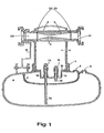
Une forme d'exécution de l'invention est décrite ci-après à à titre indicatif et nullement limitatif. Elle sera mieux comprise à l'aide de la description qui suit en référence à l'unique figure du dessin schématique annexé représentant une coupe selon le diamètre de l'appareil dans le sens longitudinal de la tuyère.An embodiment of the invention is described below by way of indication and in no way limitative. It will be better understood with the aid of the description which follows with reference to the single figure of the appended schematic drawing representing a section along the diameter of the device in the longitudinal direction of the nozzle.
Le dispositif comprend au moins un tube 1 portant une tuyère 2, traversant une chambre d'atomisation, et communiquant avec elle par au moins un orifice périphérique 3. Cette chambre comporte à sa base des moyens de fixation amovible 5 sur un réservoir 6, lequel comprend à la partie haute intérieure et axialement un second réservoir plus petit 7 leur paroi supérieure étant commune. Chacun de ces réservoirs possède un bouchon de remplissage étanche à la pression 8 et 9.The device comprises at least one tube 1 carrying a nozzle 2, passing through an atomization chamber, and communicating with it by at least one peripheral orifice 3. This chamber comprises at its base removable fixing means 5 on a
Une partie de la paroi supérieure commune à ces deux réservoirs forme le fond inférieur 10 de la chambre d'atomisation 4. Sur ce fond, après perçage, est montée une platine supportant deux gicleurs 11 et 12 de débits différents, pouvant atomiser respectivement l'huile de lubrification et le produit pour éviter le givrage dans la chambre 4, ensemble ou séparément. En outre ces gicleurs sont précédés de deux mini-vannes pressostatiques 13 et 14 dont l'ouverture est commandée par la mise en dépression de la chambre d'atomisation 4 par la tuyère 2.A part of the upper wall common to these two reservoirs forms the
Ces mini-vannes pressostatiques sont placées, l'une sur le tube plongeur 15 qui alimente en huile de lubrification le gicleur 11 de faible débit à partir du petit réservoir 7, l'autre sur le tube plongeur 16 qui alimente en produit contaminant pour éviter le givrage le gicleur 12 à plus grand débit, à partir du grand réservoir 6, après avoir traversé le fond du petit réservoir de manière étanche.These mini pressostatic valves are placed, one on the
La partie supérieure des rèservoirs 6 et 7 communique, par l'intermédiaire de deux petits robinets à trois voies 17 et 18 et d'un petit tube 19 avec l'élément 20 collecteur d'arrivée d'air du compresseur (pression 7 kg manométrique) en amont de la tuyère 2. Les robinets à trois voies 17 et 18 peuvent également relier directement avec l'atmosphère les réservoirs 6 et 7. C'est cette pression d'air de 7 kg appliquée dans la partie supérieure des réservoirs 6 et 7 qui permet l'atomisation dans la chambre 4 lorsque celle-ci est mise en dépression par la tuyère 2, faisant s'ouvrir les mini-vannes pressostatiques 13 et 14.The upper part of the
On voit que suivant la position des deux robinets à trois voies 17 et 18 on peut mettre en pression (7 kg) l'un ou l'autre des réservoirs 6 et 7 ou les deux à la fois, et par conséquent atomiser l'un ou l'autre des produits ou les deux à la fois.It can be seen that, depending on the position of the two three-
On notera que la tuyère 2 est interchangeable et qu'elle est maintenue dans le tube porte-tuyère 1 de manière étanche (joints toriques 22 et 23 en amont et aval) par le serrage du raccord 21 servant de prise d'alimentation d'air au flexible des outils.It will be noted that the nozzle 2 is interchangeable and that it is held in the nozzle-carrying tube 1 in a sealed manner (O-rings 22 and 23 upstream and downstream) by tightening the
La zone de dépression de cette tuyère est en communication avec le ou les orifices périphériques 3 du tube porte-tuyère et donc avec la chambre d'atomisation 4. Les tuyères sont interchangeables car leur débit doit être calculé en fonction de la consommation de l'outil en assurant une détente de l'air comprimé de 7 kg de pression amont (compresseur) à 6 Kg manométriques, pression d'utilisation des outils, afin d'obtenir une bonne aspiration dans la chambre d'atomisation lors de la marche de l'outil.The vacuum zone of this nozzle is in communication with the peripheral orifice (s) 3 of the nozzle-holder tube and therefore with the
Ces tuyères peuvent être fabriquées en métal ou en matière plastique, voire en verre, par usinage classique ou par moulage, sans sortir du cadre de l'invention.These nozzles can be made of metal or plastic, or even glass, by conventional machining or by molding, without departing from the scope of the invention.
Quand ce dispositif est employé sur les chantiers de travaux publics, le flexible venant du compresseur est raccordé au collecteur 20, et le flexible alimentant le brise-béton au raccord de sortie 21. Pendant l'arrêt du brise-béton, il n'y a aucun débit d'air comprimé, la pression est partout de 7 Kg en amont de la tuyère 2, et, suivant la position des robinets à trois voies 17 et 18 dans le ou les réservoirs 6 et 7, en aval de la tuyère, dans la tuyère elle-même, et donc dans la chambre d'atomisation 4. Les mini-vannes pressostatiques 13 et 14 d'alimentation des gicleurs 11 et 12 sont fermées.When this device is used on public works sites, the flexible hose coming from the compressor is connected to the manifold 20, and the flexible hose supplying the concrete breaker to the
Quand on met le brise-béton en action, il consomme de l'air comprimé, par exemple 100 m3/H à 6 Kg, détente obtenue par la tuyère à ce débit.When the concrete breaker is put into action, it consumes compressed air, for example 100 m 3 / H at 6 Kg, expansion obtained by the nozzle at this flow rate.
La tuyère aspire dans le tube porte-tuyère 1 et donc dans la chambre 4 qui se trouve alors en dépression, les mini-vannes pressostatiques 13 et 14 s'ouvrent, l'alimentation des gicleurs 11 et 12 peut se faire sous pression de 7 kg si le ou les robinets à trois 17 et 18 mettent le ou les réservoirs en communication avec la pression en amont de la tuyère (collecteur 20).The nozzle sucks in the nozzle-carrying tube 1 and therefore in the
En ce qui concerne le produit de contamination pour empêcher le givrage le but recherché est double:
- a) doper l'eau en phase vapeur ou condensée contenue dans l'air comprimé alimentant les outils pneumatiques à percussion de manière à abaisser son point de congélation pour éviter le givrage et le gel provoqué par le froid intense dû à la détente de l'air;
- b) éviter également la formation de givre par l'air atmosphérique environnant qui se condense sur les parties extérieures froides des outils.
- a) boost water in vapor or condensed phase contained in the compressed air supplying the pneumatic impact tools so as to lower its freezing point to avoid icing and freezing caused by the intense cold due to the expansion of the air;
- b) also avoid the formation of frost by the surrounding atmospheric air which condenses on the cold outside parts of the tools.
Pour résoudre le premier problème il faut un antigel très hydrophile contenant des inhibiteurs de corrosion et un produit anti-mousse; de plus, il faut que sa viscosité permette une atomisation (50 microns) avec la pression dont on dispose.To solve the first problem, a very hydrophilic antifreeze containing corrosion inhibitors and an anti-foam product is required; in addition, its viscosity must allow atomization (50 microns) with the pressure available.
Pour résoudre le second problème, il faut, autant que faire se peut, éviter la cristallisation de l'eau qui se condense sur les parties extérieures froides des outils. A ce sujet, on a remarqué que la cristallisation de l'eau (formation de givre et de glace) est surtout provoquée par la formation de ponts d'hydrogène par lesquels les atomes d'oxygène de deux molécules voisines sont liées et qui déjà dans l'eau sont associées dans les molécules. On peut considérer que dans une telle structure chaque atome d'oxygène est entouré de quatre autres atomes d'oxygène en tétraèdre et que sur chaque ligne de liaison de 2 atomes d'oxygène se trouve un atome d'hydrogène formant un pont d'hydrogène. Un atome d'oxygène n'est donc pas seulement lié à deux atomes d'hydrogène par covalence mais également par les ponts d'hydrogène à deux autres d'oxygène.To solve the second problem, it is necessary, as much as possible, to avoid the crystallization of the water which condenses on the cold external parts of the tools. In this regard, it has been noted that the crystallization of water (formation of frost and ice) is mainly caused by the formation of hydrogen bridges by which the oxygen atoms of two neighboring molecules are linked and which already in water are associated in molecules. We can consider that in such a structure each oxygen atom is surrounded by four other oxygen atoms in tetrahedron and that on each connecting line of 2 oxygen atoms is a hydrogen atom forming a hydrogen bridge . An oxygen atom is therefore not only linked to two hydrogen atoms by covalence but also by the hydrogen bridges to two others of oxygen.
On a récemment remarqué que les hydroxydes de métaux alcalins à très faibles doses perturbent la formation de ces ponts d'hydrogène et donc la formation de givre.It has recently been observed that the hydroxides of alkali metals at very low doses disturb the formation of these hydrogen bridges and therefore the formation of frost.
Après plusieurs essais et dosages de différents alcools liquides abaissant le point de congélation et pour obtenir un produit finement atomisable ayant donc une grande surface de contact avec les vapeurs d'eau et l'eau condensée contenue dans l'air à doper, on a retenu: l'éthylène-glycol et l'alcool méthylique.After several tests and dosages of different liquid alcohols lowering the freezing point and to obtain a finely atomizable product therefore having a large contact surface with the water vapors and the condensed water contained in the air to be doped, we retained : ethylene glycol and methyl alcohol.
L'éthylène-glycol préféré est le monoéthylène-glycol que l'on trouve dans le commerce, comportant déjà des inhibiteurs de corrosion tels que nitrite, tétraborate et benzoate de sodium.The preferred ethylene glycol is commercially available monoethylene glycol, which already has corrosion inhibitors such as sodium nitrite, tetraborate and benzoate.
Parmi les agents anti-mousse polyglycoliques compatibles que l'on prépare généralement en ajoutant de l'oxyde d'éthylène à du polypropylène-glycol on a obtenu de bons résultats avec le »Plutonic L 61«, marque déposée de la Wyandotte Chemical Company.Among the compatible polyglycolic defoamers which are generally prepared by adding ethylene oxide to polypropylene glycol, good results have been obtained with "Plutonic L 61", registered trademark of the Wyandotte Chemical Company.
Enfin l'hydroxyde de métaux alcalins préféré est l'hydroxyde de sodium aqueux à 50% qui, outre les effets mentionnés, a l'avantage quand il est combiné avec le tétraborate de sodium de transformer une partie des ions tétraborates en ions métaborates.Finally, the preferred alkali metal hydroxide is 50% aqueous sodium hydroxide which, in addition to the effects mentioned, has the advantage when it is combined with sodium tetraborate of transforming part of the tetraborate ions into metaborate ions.
Un exemple, nullement limitatif de l'invention qui a donné de bons résultats est décrit ci-dessous:
- On a mélangé 600,0 g de monoéthylène-glycol du commerce comportant déjà des inhibiteurs de corrosion, notamment les tétraborate et benzoate de sodium, 387,0 g d'alcool méthylique, puis on a ajouté 3,0 g d'hydroxyde de sodium aqueux à 50% et enfin 10,0 g de »Plutonic L 61 «.
- 600.0 g of commercial monoethylene glycol already containing corrosion inhibitors, in particular sodium tetraborate and benzoate, 387.0 g of methyl alcohol were mixed, then 3.0 g of sodium hydroxide were added 50% aqueous and finally 10.0 g of »Plutonic L 61«.
Avec le dispositif selon l'invention, les liquides des réservoirs 6 et 7 sont atomisés au niveau des gicleurs 11 et 12 et un brouillard se trouve diffus dans la chambre 4. Par suite de la dépression créée en 3 par la tuyère, les fines gouttelettes de ce brouillard sont aspirées au niveau du passage étroit du Venturi, où existe un débit d'air à grande vitesse. Les gouttelettes de brouillard y sont encore divisées et sont ensuite entraînées vers le brise-béton. Elles jouent le rôle de contaminant pour l'eau qui se trouve dans l'air comprimé utilisé pour la commande du brise-béton, et en abaissant le point de congélation de cette eau, elles évitent le givrage à l'échappement et au niveau de l'amortisseur de broit.With the device according to the invention, the liquids of the
Les gouttelettes d'huile de lubrification qui se trouvent le cas échéant entraînées par l'air comprimé vers l'outil assurent sa lubrification permanente.The lubricating oil droplets which, if necessary, are entrained by the compressed air towards the tool ensure its permanent lubrication.
Claims (10)
Priority Applications (1)
| Application Number | Priority Date | Filing Date | Title |
|---|---|---|---|
| AT82400891T ATE14622T1 (en) | 1981-05-15 | 1982-05-14 | DEVICE AND PRODUCT FOR PREVENTING ICE FORMATION IN PNEUMATIC DEVICES, ESPECIALLY IMPACT DEVICES. |
Applications Claiming Priority (2)
| Application Number | Priority Date | Filing Date | Title |
|---|---|---|---|
| FR8109898 | 1981-05-15 | ||
| FR8109898A FR2505715A1 (en) | 1981-05-15 | 1981-05-15 | DEVICE AND PRODUCT FOR PREVENTING THE ENHANCEMENT OF PNEUMATIC TOOLS, IN PARTICULAR THOSE WITH PERCUSSION |
Publications (2)
| Publication Number | Publication Date |
|---|---|
| EP0065915A1 EP0065915A1 (en) | 1982-12-01 |
| EP0065915B1 true EP0065915B1 (en) | 1985-07-31 |
Family
ID=9258606
Family Applications (1)
| Application Number | Title | Priority Date | Filing Date |
|---|---|---|---|
| EP82400891A Expired EP0065915B1 (en) | 1981-05-15 | 1982-05-14 | Apparatus and product for preventing ice deposit on pneumatic tools, especially percussion tools |
Country Status (4)
| Country | Link |
|---|---|
| EP (1) | EP0065915B1 (en) |
| AT (1) | ATE14622T1 (en) |
| DE (1) | DE3265051D1 (en) |
| FR (1) | FR2505715A1 (en) |
Families Citing this family (4)
| Publication number | Priority date | Publication date | Assignee | Title |
|---|---|---|---|---|
| FR2597008B1 (en) * | 1986-04-10 | 1988-07-15 | Stutzmann Georges | APPARATUS FOR MAINTAINING PNEUMATIC TOOLS |
| DE10002414A1 (en) * | 2000-01-21 | 2001-08-09 | Festo Ag & Co | Additive atomizing device |
| AT507433B1 (en) | 2008-12-15 | 2010-05-15 | Parker Origa Pneumatik Gmbh | AIR LUBRICATOR |
| CN115807648B (en) * | 2022-12-30 | 2023-06-23 | 胜利油田奥凯龙石油工程有限公司 | Automatic change rig freeze-proof heat preservation device of control |
Family Cites Families (4)
| Publication number | Priority date | Publication date | Assignee | Title |
|---|---|---|---|---|
| FR1234635A (en) * | 1958-09-29 | 1960-10-18 | Bendix Westinghouse Automotive | Antifreeze solution dispenser device |
| FR1276401A (en) * | 1960-01-23 | 1961-11-17 | Magneti Marelli Spa | Improvement in anti-freezing devices used in compressed air installations, in particular for vehicles |
| NL7100621A (en) * | 1971-01-18 | 1972-07-20 | ||
| GB2032808B (en) * | 1978-11-01 | 1982-10-20 | Kolpin Otdel V Ni I P Konstruk | Vortex-type mist generator |
-
1981
- 1981-05-15 FR FR8109898A patent/FR2505715A1/en active Granted
-
1982
- 1982-05-14 DE DE8282400891T patent/DE3265051D1/en not_active Expired
- 1982-05-14 EP EP82400891A patent/EP0065915B1/en not_active Expired
- 1982-05-14 AT AT82400891T patent/ATE14622T1/en not_active IP Right Cessation
Also Published As
| Publication number | Publication date |
|---|---|
| ATE14622T1 (en) | 1985-08-15 |
| FR2505715A1 (en) | 1982-11-19 |
| EP0065915A1 (en) | 1982-12-01 |
| DE3265051D1 (en) | 1985-09-05 |
| FR2505715B1 (en) | 1983-07-01 |
Similar Documents
| Publication | Publication Date | Title |
|---|---|---|
| US6071355A (en) | Method for cleaning a transmission | |
| EP0065915B1 (en) | Apparatus and product for preventing ice deposit on pneumatic tools, especially percussion tools | |
| US7198057B2 (en) | Freeze-free water hose | |
| BE1013305A5 (en) | Distribution of installation of liquid hydrocarbons equipped with vapor recovery means. | |
| CN106884394B (en) | A kind of road guardrail cleaning vehicle | |
| CN108970824B (en) | Anti-icing device of dry fog dust suppression nozzle | |
| CN111167649A (en) | Spraying storage device | |
| JPH10153270A (en) | Valve device for air tank | |
| EP0525164B1 (en) | Atomizing head for spraying liquids | |
| JP3028181B2 (en) | Coolant filling device | |
| US20040069570A1 (en) | Mist distributor with integral air solenoid valve | |
| CN214743427U (en) | Fuel switch used on oil supply system | |
| RU2162040C1 (en) | Method of and system for automatic filling of water and dispensing column for implementing this method | |
| CN219882798U (en) | Concrete curing box that protective properties is good | |
| EP2213858B1 (en) | Device for heating the windscreen-washer liquid of an automobile | |
| CN220779236U (en) | Mobile fire station | |
| CN219131676U (en) | Cooling device for aluminum alloy direct-reading spectrum sample surface processing | |
| CN211801904U (en) | Spraying storage device | |
| US10557679B2 (en) | Fire alarm and tool oiling system | |
| CN202412972U (en) | Glue spraying mechanism with functions of broken wire recovery and automatic cleaning | |
| JPS5824880Y2 (en) | galvanometer | |
| CN201891465U (en) | Crankcase respirator | |
| CN208313637U (en) | A kind of chemistry glue-dispenser sampler | |
| CN108889064B (en) | Application method of anti-icing device of dry fog dust suppression nozzle | |
| RU1830049C (en) | Device for gas cleaning and for liquid medium release |
Legal Events
| Date | Code | Title | Description |
|---|---|---|---|
| PUAI | Public reference made under article 153(3) epc to a published international application that has entered the european phase |
Free format text: ORIGINAL CODE: 0009012 |
|
| AK | Designated contracting states |
Designated state(s): AT BE CH DE FR GB IT LU NL SE |
|
| 17P | Request for examination filed |
Effective date: 19830531 |
|
| ITF | It: translation for a ep patent filed | ||
| GRAA | (expected) grant |
Free format text: ORIGINAL CODE: 0009210 |
|
| AK | Designated contracting states |
Designated state(s): AT BE CH DE FR GB IT LI LU NL SE |
|
| REF | Corresponds to: |
Ref document number: 14622 Country of ref document: AT Date of ref document: 19850815 Kind code of ref document: T |
|
| REF | Corresponds to: |
Ref document number: 3265051 Country of ref document: DE Date of ref document: 19850905 |
|
| PLBE | No opposition filed within time limit |
Free format text: ORIGINAL CODE: 0009261 |
|
| STAA | Information on the status of an ep patent application or granted ep patent |
Free format text: STATUS: NO OPPOSITION FILED WITHIN TIME LIMIT |
|
| 26N | No opposition filed | ||
| ITTA | It: last paid annual fee | ||
| PGFP | Annual fee paid to national office [announced via postgrant information from national office to epo] |
Ref country code: FR Payment date: 19920415 Year of fee payment: 11 |
|
| PGFP | Annual fee paid to national office [announced via postgrant information from national office to epo] |
Ref country code: GB Payment date: 19920506 Year of fee payment: 11 |
|
| PGFP | Annual fee paid to national office [announced via postgrant information from national office to epo] |
Ref country code: CH Payment date: 19920514 Year of fee payment: 11 |
|
| PGFP | Annual fee paid to national office [announced via postgrant information from national office to epo] |
Ref country code: DE Payment date: 19920521 Year of fee payment: 11 |
|
| PGFP | Annual fee paid to national office [announced via postgrant information from national office to epo] |
Ref country code: LU Payment date: 19920525 Year of fee payment: 11 |
|
| PGFP | Annual fee paid to national office [announced via postgrant information from national office to epo] |
Ref country code: SE Payment date: 19920526 Year of fee payment: 11 |
|
| PGFP | Annual fee paid to national office [announced via postgrant information from national office to epo] |
Ref country code: AT Payment date: 19920529 Year of fee payment: 11 |
|
| PGFP | Annual fee paid to national office [announced via postgrant information from national office to epo] |
Ref country code: NL Payment date: 19920531 Year of fee payment: 11 |
|
| PGFP | Annual fee paid to national office [announced via postgrant information from national office to epo] |
Ref country code: BE Payment date: 19920616 Year of fee payment: 11 |
|
| EPTA | Lu: last paid annual fee | ||
| PG25 | Lapsed in a contracting state [announced via postgrant information from national office to epo] |
Ref country code: LU Free format text: LAPSE BECAUSE OF NON-PAYMENT OF DUE FEES Effective date: 19930514 Ref country code: GB Effective date: 19930514 Ref country code: AT Effective date: 19930514 |
|
| PG25 | Lapsed in a contracting state [announced via postgrant information from national office to epo] |
Ref country code: SE Effective date: 19930515 |
|
| PG25 | Lapsed in a contracting state [announced via postgrant information from national office to epo] |
Ref country code: LI Effective date: 19930531 Ref country code: CH Effective date: 19930531 Ref country code: BE Effective date: 19930531 |
|
| BERE | Be: lapsed |
Owner name: S.I.M.O. S.A. Effective date: 19930531 |
|
| PG25 | Lapsed in a contracting state [announced via postgrant information from national office to epo] |
Ref country code: NL Effective date: 19931201 |
|
| GBPC | Gb: european patent ceased through non-payment of renewal fee |
Effective date: 19930514 |
|
| NLV4 | Nl: lapsed or anulled due to non-payment of the annual fee | ||
| PG25 | Lapsed in a contracting state [announced via postgrant information from national office to epo] |
Ref country code: FR Effective date: 19940131 |
|
| REG | Reference to a national code |
Ref country code: CH Ref legal event code: PL |
|
| PG25 | Lapsed in a contracting state [announced via postgrant information from national office to epo] |
Ref country code: DE Effective date: 19940201 |
|
| REG | Reference to a national code |
Ref country code: FR Ref legal event code: ST |
|
| EUG | Se: european patent has lapsed |
Ref document number: 82400891.6 Effective date: 19931210 |