EP0065910A1 - Magnetic circuit, inductance utilizing such a circuit and method of producing inductances - Google Patents
Magnetic circuit, inductance utilizing such a circuit and method of producing inductances Download PDFInfo
- Publication number
- EP0065910A1 EP0065910A1 EP82400879A EP82400879A EP0065910A1 EP 0065910 A1 EP0065910 A1 EP 0065910A1 EP 82400879 A EP82400879 A EP 82400879A EP 82400879 A EP82400879 A EP 82400879A EP 0065910 A1 EP0065910 A1 EP 0065910A1
- Authority
- EP
- European Patent Office
- Prior art keywords
- magnetic circuit
- grooves
- magnetic
- bar
- electrical connection
- Prior art date
- Legal status (The legal status is an assumption and is not a legal conclusion. Google has not performed a legal analysis and makes no representation as to the accuracy of the status listed.)
- Granted
Links
- 238000000034 method Methods 0.000 title claims description 14
- 238000004519 manufacturing process Methods 0.000 claims abstract description 5
- 238000004804 winding Methods 0.000 claims description 8
- 239000002184 metal Substances 0.000 claims description 4
- 229910052751 metal Inorganic materials 0.000 claims description 4
- 238000000926 separation method Methods 0.000 claims description 4
- 239000000853 adhesive Substances 0.000 claims description 2
- 230000001070 adhesive effect Effects 0.000 claims description 2
- 238000001465 metallisation Methods 0.000 claims description 2
- 238000003825 pressing Methods 0.000 claims description 2
- RYGMFSIKBFXOCR-UHFFFAOYSA-N Copper Chemical compound [Cu] RYGMFSIKBFXOCR-UHFFFAOYSA-N 0.000 description 4
- 239000000758 substrate Substances 0.000 description 4
- BQCADISMDOOEFD-UHFFFAOYSA-N Silver Chemical compound [Ag] BQCADISMDOOEFD-UHFFFAOYSA-N 0.000 description 3
- 238000005520 cutting process Methods 0.000 description 3
- 229910052709 silver Inorganic materials 0.000 description 3
- 239000004332 silver Substances 0.000 description 3
- 238000000151 deposition Methods 0.000 description 2
- XEEYBQQBJWHFJM-UHFFFAOYSA-N Iron Chemical compound [Fe] XEEYBQQBJWHFJM-UHFFFAOYSA-N 0.000 description 1
- 229910052802 copper Inorganic materials 0.000 description 1
- 239000010949 copper Substances 0.000 description 1
- 230000008021 deposition Effects 0.000 description 1
- 229910003460 diamond Inorganic materials 0.000 description 1
- 239000010432 diamond Substances 0.000 description 1
- 230000000694 effects Effects 0.000 description 1
- 238000005538 encapsulation Methods 0.000 description 1
- 229920006332 epoxy adhesive Polymers 0.000 description 1
- 230000004907 flux Effects 0.000 description 1
- 239000003292 glue Substances 0.000 description 1
- 238000002347 injection Methods 0.000 description 1
- 239000007924 injection Substances 0.000 description 1
- 239000006247 magnetic powder Substances 0.000 description 1
- 239000000463 material Substances 0.000 description 1
- 238000000465 moulding Methods 0.000 description 1
- 229920002635 polyurethane Polymers 0.000 description 1
- 239000004814 polyurethane Substances 0.000 description 1
- 229920005989 resin Polymers 0.000 description 1
- 239000011347 resin Substances 0.000 description 1
- 238000005476 soldering Methods 0.000 description 1
- 239000007787 solid Substances 0.000 description 1
- 229920001169 thermoplastic Polymers 0.000 description 1
- 229920001187 thermosetting polymer Polymers 0.000 description 1
- 239000004416 thermosoftening plastic Substances 0.000 description 1
- 238000003466 welding Methods 0.000 description 1
- 229910000859 α-Fe Inorganic materials 0.000 description 1
Images


Classifications
-
- H—ELECTRICITY
- H01—ELECTRIC ELEMENTS
- H01F—MAGNETS; INDUCTANCES; TRANSFORMERS; SELECTION OF MATERIALS FOR THEIR MAGNETIC PROPERTIES
- H01F17/00—Fixed inductances of the signal type
- H01F17/04—Fixed inductances of the signal type with magnetic core
- H01F17/045—Fixed inductances of the signal type with magnetic core with core of cylindric geometry and coil wound along its longitudinal axis, i.e. rod or drum core
-
- H—ELECTRICITY
- H01—ELECTRIC ELEMENTS
- H01F—MAGNETS; INDUCTANCES; TRANSFORMERS; SELECTION OF MATERIALS FOR THEIR MAGNETIC PROPERTIES
- H01F41/00—Apparatus or processes specially adapted for manufacturing or assembling magnets, inductances or transformers; Apparatus or processes specially adapted for manufacturing materials characterised by their magnetic properties
- H01F41/02—Apparatus or processes specially adapted for manufacturing or assembling magnets, inductances or transformers; Apparatus or processes specially adapted for manufacturing materials characterised by their magnetic properties for manufacturing cores, coils, or magnets
- H01F41/0206—Manufacturing of magnetic cores by mechanical means
- H01F41/0246—Manufacturing of magnetic circuits by moulding or by pressing powder
-
- H—ELECTRICITY
- H01—ELECTRIC ELEMENTS
- H01F—MAGNETS; INDUCTANCES; TRANSFORMERS; SELECTION OF MATERIALS FOR THEIR MAGNETIC PROPERTIES
- H01F27/00—Details of transformers or inductances, in general
- H01F27/34—Special means for preventing or reducing unwanted electric or magnetic effects, e.g. no-load losses, reactive currents, harmonics, oscillations, leakage fields
- H01F2027/348—Preventing eddy currents
Definitions
- the present invention relates to a magnetic circuit for inductance, an inductor using such a magnetic circuit and a method of manufacturing said magnetic circuit for the production of said inductors.
- Inductors in particular miniature inductors for high frequencies, are most generally obtained by winding an enameled copper wire, in the groove of a magnetic pulley made of ferrite or iron powder.
- This pulley is generally obtained either by injection or molding of magnetic powder mixed with a thermo-plastic or thermosetting material, or by size, from a cylindrical bar using a diamond wheel. In the latter case, a certain number of grooves can be machined successively or simultaneously on the same cylindrical bar. There is thus obtained a plurality of grooves regularly distributed over this bar, grooves in which the copper wire is wound. This winding operation can be carried out on all of the pulleys constituting the bar, then each individual pulley is obtained by cutting up said bar.
- the magnetic circuit according to the invention makes it possible to avoid these drawbacks.
- it is characterized in that it is constituted by a parallelepiped comprising at least two grooves, one upper and the other lower, arranged substantially one above the other and intended to receive a winding, said circuit having substantially the shape of an H in a plane perpendicular to the grooves.
- the circuit according to the invention is characterized in that the two grooves are of different width.
- the magnetic circuits according to the invention are preferably provided at their lower parts with electrical connection means, these may for example be either metallic deposits made directly on the lower part of the two branches surrounding the lower groove, or metallized substrates fixed under these two branches.
- the upper groove, narrower than the lower groove will therefore make it possible to limit the eddy currents in the lower metal parts as much as possible and to favor as much as possible the passage of the magnetic flux in the upper air gap, which corresponds to the part of the circuit with the lowest reluctance. This effect is further improved when the branches surrounding the lower throat are longer than the branches surrounding the upper throat.
- the electrical connection means as defined above can be produced according to different variants: they can be constituted for example by direct metallic deposits on the branches surrounding the lower groove. They can also be constituted by metal tabs adapted to the printed circuit, these being glued directly to the magnetic core or through an insulating part.
- the invention also relates to magnetic inductors comprising a magnetic circuit as defined above, said magnetic circuit being provided with a suitable winding. The ends of this winding will be electrically connected to the electrical connection means.
- the invention further relates to a method for producing magnetic circuits for inductors, method in which a plurality of grooves are produced in a magnetic bar, thereby determining a plurality of magnetic circuits which are then separated from each other between two successive grooves, said process being characterized in that a rectangular bar is chosen in which a plurality of grooves parallel to one another are produced on the upper and lower faces, said grooves being substantially aligned vertically in pairs.
- grooves can be produced by pressing or by horizontal, sequential or simultaneous grooving, by any suitable means well known to those skilled in the art.
- the method according to the invention is characterized in that the lower parts of the bar situated between the lower grooves are provided with means of electrical connections before the separation of the magnetic circuits.
- a parallelepiped having a rectangular section will be chosen and the grooving will be carried out parallel to the lateral plane of the bar, making it possible to obtain, after separation of the magnetic circuits having an H shape in a plane perpendicular to the lateral plane of the bar.
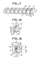
- the parallelepiped bar 1 which has a rectangular side face 2, has been subjected to a grooving operation after which a plurality of upper grooves such as 7 and lower grooves such as 6 have been produced. These grooves are separated by a solid part 8.
- the non-grooved parts of the front face of the parallelepiped 1 such as 4 and 5 are then cut along the axes of symmetry 9 and 10 to form magnetic circuits according to the invention having a section H-shaped
- FIG 2 there is shown one of the magnetic circuits obtained after cutting the bar shown in Figure 1.
- the groove 7 has two vertical walls 21 and 23 and a horizontal wall 22 which limit the central part 8 of the magnetic circuit.
- the lower groove 6 has walls arranged in the same way as that of the groove 7.
- the upper groove 7 is surrounded by two upper branches 17 and 18 while the lower groove 6 is surrounded by two lower branches 15 and 3.
- connection means 19 and 20 are shown which in this case are metallization obtained for example by depositing silver paste followed by appropriate baking.
- FIG. 3 represents a magnetic circuit as represented in FIG. 2, on which the same elements bear the same references.
- This FIG. 3 also shows the coil 24 made up of several turns wound inside the grooves 6 and 7, the ends 25 and 26 of said coil being respectively connected to the connection means 20 and 19.
- the width a of the upper groove 7 is much less than the width b of the lower groove 6.
- the ratio between the width b between the lower legs and the width a between the upper legs will be between 1.5 and 3.
- the ratio between the height of the lower legs d and the height of the upper legs c will be between 1.5 and 2 and preferably of the order of 2.
- an inductor is shown as a sectional view in Figure 3, inductor having electrical connection means particularly suitable for fixing it on hybrid circuit supports.
- the ends of the winding, such as 25 are respectively connected to metallized tapes such as 28 and 29, the connection being made in the extension of the axis of the groove 7.
- the electrical connection between the end 25 and the metallized tape 28 is therefore located substantially in the middle of it.
- the magnetic circuit is fixed on an insulating support such as 30 using a suitable adhesive such as a polyurethane epoxy adhesive, etc., this insulating support comprising metallized tapes 28 and 29.
- the lateral rectangular face 16 of the magnetic circuit is arranged in the extension of the lateral face of the insulating support 30.
- FIG. 5 A another alternative embodiment of the electrical connection means is attached, fixed to the lower legs of the magnetic circuit.
- these con electrical connections 19 and 20 are produced by metallic deposition such as a silver paste.
- the ends 25 and 26 of the winding are then electrically welded on the connections 19 and 20 previously tinned, as shown in FIG. 5 B which is a section along the axis BB of the magnetic circuit shown in FIG. 5 A.
- FIG. 6 represents another variant embodiment of the circuit shown in FIG. 4, the only difference being the presence of two radial outputs 31 and 32 for the printed circuit, outputs connected respectively to the electrical connection means 28 and 29.
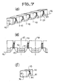
- FIG. 7 represents the different stages of another variant embodiment of the method according to the invention.
Abstract
La présente invention concerne un circuit magnétique pour inductance ainsi que des inductances utilisant un tel circuit magnétique. Elle concerne également un procédé de réalisation dudit circuit magnétique. Selon l'invention, le circuit magnétique est constitué par un parallélépipède comportant au moins deux gorges (6, 7) disposées sensiblement l'une au-dessus de l'autre dans lesquelles est disposé un bobinage (24), ledit circuit magnétique ayant sensiblement la forme d'un H dans un plan perpendiculaire aux gorges. Les branches inférieures (3, 15) dudit circuit magnétique sont munies de moyens de connexions électriques (19, 20). Ceci permet de fixer solidement et sans difficulté les inductances ainsi réalisées soit sur des circuits imprimés, soit directement sur des supports de circuits hybrides. Application : inductance miniature.The present invention relates to a magnetic circuit for inductor as well as inductors using such a magnetic circuit. It also relates to a method for producing said magnetic circuit. According to the invention, the magnetic circuit is constituted by a parallelepiped comprising at least two grooves (6, 7) disposed substantially one above the other in which a coil (24) is disposed, said magnetic circuit having substantially the shape of an H in a plane perpendicular to the grooves. The lower branches (3, 15) of said magnetic circuit are provided with electrical connection means (19, 20). This allows the inductors thus produced to be securely fixed without difficulty either on printed circuits or directly on hybrid circuit supports. Application: miniature inductor.
Description
La présente invention concerne un circuit magnétique pour inductance, une inductance utilisant un tel circuit magnétique ainsi qu'un procédé de fabrication dudit circuit magnétique pour la réalisation desdites inductances.The present invention relates to a magnetic circuit for inductance, an inductor using such a magnetic circuit and a method of manufacturing said magnetic circuit for the production of said inductors.
Les inductances, en particulier les inductances miniatures pour hautes fréquences, sont le plus généralement obtenues en bobinant un fil de cuivre émaillé, dans la gorge d'une poulie magnétique en ferrite ou en poudre de fer. Cette poulie est généralement obtenue soit par injection ou moulage de poudre magnétique mélangée à une matière thermo-plastique ou thermo-durcissable, soit par taille, d'un barreau cylindrique à l'aide d'une meule diamantée. Dans ce dernier cas, un certain de nombre de gorges peuvent être usinées successivement ou simultanément sur le même barreau cylindrique. On obtient ainsi une pluralité de gorges régulièrement réparties sur ce barreau, gorges dans lesquelles est bobiné le fil de cuivre. Cette opération de bobinage peut être effectuée sur l'ensemble des poulies constituant le barreau puis chaque poulie individuelle est obtenue par tronçonnage dudit barreau.Inductors, in particular miniature inductors for high frequencies, are most generally obtained by winding an enameled copper wire, in the groove of a magnetic pulley made of ferrite or iron powder. This pulley is generally obtained either by injection or molding of magnetic powder mixed with a thermo-plastic or thermosetting material, or by size, from a cylindrical bar using a diamond wheel. In the latter case, a certain number of grooves can be machined successively or simultaneously on the same cylindrical bar. There is thus obtained a plurality of grooves regularly distributed over this bar, grooves in which the copper wire is wound. This winding operation can be carried out on all of the pulleys constituting the bar, then each individual pulley is obtained by cutting up said bar.
Cependant, de telles poulies ne sont pas directement soudables sur des circuits imprimés. En effet, les deux extrémités de l'inductance sont les fils de cuivre souples et ceux-ci peuvent difficilement être introduits directement dans les trous des circuits imprimés et d'autre part, leur rigidité est insuffisante pour éviter les risques de cassure ou de désoudage des fils lorsque ledit circuit est soumis à des vibrations. Pour résoudre ce problème, on a généralement recours soit à un boîtier d'encapsulation desdites inductances soit à un surmoulage à l'aide d'une résine.However, such pulleys are not directly weldable on printed circuits. Indeed, the two ends of the inductor are flexible copper wires and these can hardly be introduced directly into the holes of the printed circuits and on the other hand, their rigidity is insufficient to avoid the risks of breakage or desoldering. wires when said circuit is subjected to vibrations. To resolve this problem, recourse is generally had either to an encapsulation box for said inductors or to overmolding using a resin.
Le circuit magnétique selon l'invention permet d'éviter ces inconvénients. Dans ce but, il est caractérisé en ce qu'il est constitué par un parallélépipède comportant au moins deux gorges, l'une supérieure et l'autre inférieure, disposées sensiblement l'une au-dessus de l'autre et destinées à recevoir un bobinage, ledit circuit ayant sensiblement la forme d'un H dans un plan perpendiculaire aux gorges.The magnetic circuit according to the invention makes it possible to avoid these drawbacks. For this purpose, it is characterized in that it is constituted by a parallelepiped comprising at least two grooves, one upper and the other lower, arranged substantially one above the other and intended to receive a winding, said circuit having substantially the shape of an H in a plane perpendicular to the grooves.
A l'aide d'un tel circuit magnétique, on peut, ainsi qu'on le verra par la suite, réalisé aisément des inductances qui peuvent être montées directement sur un circuit imprimé ou sur un circuit hybride.Using such a magnetic circuit, it is possible, as will be seen hereinafter, easily produced inductors which can be mounted directly on a printed circuit or on a hybrid circuit.
Selon un mode préférentiel de réalisation, le circuit selon l'invention est caractérisé en ce que les deux gorges sont de largeur différente. En effet, les circuits magnétiques selon l'invention sont de préférence munis à leurs parties inférieures de moyens de connexions électriques, ceux-ci pouvant être par exemple soit des dépôts métalliques effectués directement sur la partie inférieure des deux branches entourant la gorge inférieure, soit des substrats métallisés fixés sous ces deux branches. De préférence, la gorge supérieure, moins large que la gorge inférieure permettra donc de limiter au maximum les courants de Foucault dans les parties métalliques inférieures et de favoriser au maximum le passage du flux magnétique dans l'entrefer supérieur, qui correspond à la partie du circuit ayant la plus faible réluctance. Cet effet est encore amélioré lorsque les branches entourant la gorge inférieure sont plus longues que les branches entourant la gorge supérieure.According to a preferred embodiment, the circuit according to the invention is characterized in that the two grooves are of different width. In fact, the magnetic circuits according to the invention are preferably provided at their lower parts with electrical connection means, these may for example be either metallic deposits made directly on the lower part of the two branches surrounding the lower groove, or metallized substrates fixed under these two branches. Preferably, the upper groove, narrower than the lower groove will therefore make it possible to limit the eddy currents in the lower metal parts as much as possible and to favor as much as possible the passage of the magnetic flux in the upper air gap, which corresponds to the part of the circuit with the lowest reluctance. This effect is further improved when the branches surrounding the lower throat are longer than the branches surrounding the upper throat.
Les moyens de connexions électriques tels que définis ci-dessus peuvent être réalisés selon différentes variantes : ils peuvent être constitués par exemple par des dépôts métalliques directs sur les branches entourant la gorge inférieure. Ils peuvent être également constitués par des pattes métalliques adaptées au circuit imprimé, celles-ci étant collées directement sur le noyau magnétique ou par l'intermédiaire d'une partie isolante.The electrical connection means as defined above can be produced according to different variants: they can be constituted for example by direct metallic deposits on the branches surrounding the lower groove. They can also be constituted by metal tabs adapted to the printed circuit, these being glued directly to the magnetic core or through an insulating part.
L'invention concerne également des inductances magnétiques comportant un circuit magnétique tel que défini ci-dessus, ledit circuit magnétique étant muni d'un bobinage approprié. Les extrémités de ce bobinage seront reliées électriquement aux moyens de connexions électriques.The invention also relates to magnetic inductors comprising a magnetic circuit as defined above, said magnetic circuit being provided with a suitable winding. The ends of this winding will be electrically connected to the electrical connection means.
L'invention concerne de plus un procédé de réalisation de circuits magnétiques pour inductances, procédé dans lequel on réalise dans un barreau magnétique une pluralité de gorges déterminant ainsi une pluralité de circuits magnétiques qui sont ensuite séparés les uns des autres entre deux gorges successives, ledit procédé étant caractérisé en ce que l'on choisit un barreau parallélépipédique dans lequel on réalise sur les faces supérieure et inférieure une pluralité de gorges parallèles entre elles, lesdites gorges étant sensiblement alignées verticalement deux à deux.The invention further relates to a method for producing magnetic circuits for inductors, method in which a plurality of grooves are produced in a magnetic bar, thereby determining a plurality of magnetic circuits which are then separated from each other between two successive grooves, said process being characterized in that a rectangular bar is chosen in which a plurality of grooves parallel to one another are produced on the upper and lower faces, said grooves being substantially aligned vertically in pairs.
La réalisation de ces gorges peut être effectuée par pressage ou par rainurage horizontal, séquentiel ou simultané, par tous moyens appropriés bien connus de l'homme de l'art.These grooves can be produced by pressing or by horizontal, sequential or simultaneous grooving, by any suitable means well known to those skilled in the art.
Selon un mode préférentiel de réalisation, le procédé selon l'invention est caractérisé en ce que l'on munit les parties inférieures du barreau situées entre les gorges inférieures, de moyens de connexions électriques avant la séparation des circuits magnétiques. De préférence, on choisira un parallélépipède ayant une section rectangulaire et l'on effectuera le rainurage parallèlement au plan latéral du barreau, permettant d'obtenir après séparation des circuits magnétiques ayant une forme de H dans un plan perpendiculaire au plan latéral du barreau.According to a preferred embodiment, the method according to the invention is characterized in that the lower parts of the bar situated between the lower grooves are provided with means of electrical connections before the separation of the magnetic circuits. Preferably, a parallelepiped having a rectangular section will be chosen and the grooving will be carried out parallel to the lateral plane of the bar, making it possible to obtain, after separation of the magnetic circuits having an H shape in a plane perpendicular to the lateral plane of the bar.
L'invention sera mieux comprise à l'aide des exemples de réalisation suivants, donné à titre non limitatif, conjointement avec les figures qui représentent :
- - la figure 1, un barreau parallélépipédique après rainurage formant une pluralité de circuits magnétiques,
- - la figure 2, un circuit magnétique obtenu à partir du barreau représenté sur la figure 1,
- - la figure 3, une inductance magnétique réalisée à partir d'un circuit magnétique selon l'invention,
- - la figure 4, une variante de réalisation d'une inductance magnétique selon l'invention munie de connexions pour circuit hybride,
- - la figure 5, une inductance munie de semelles métalliques soudables et une vue en coupe de celle-ci au niveau des rainures,
- - la figure 6, une autre variante d'une inductance magnétique selon l'invention munie de pattes de connexions pour circuit imprimé,
- - la figure 7, une variante de réalisation du procédé selon l'invention.
- FIG. 1, a parallelepiped bar after grooving forming a plurality of magnetic circuits,
- FIG. 2, a magnetic circuit obtained from the bar shown in FIG. 1,
- FIG. 3, a magnetic inductance produced from a magnetic circuit according to the invention,
- FIG. 4, an alternative embodiment of a magnetic inductor according to the invention provided with connections for a hybrid circuit,
- FIG. 5, an inductor provided with weldable metal soles and a sectional view thereof at the level of the grooves,
- FIG. 6, another variant of a magnetic inductor according to the invention provided with connection tabs for a printed circuit,
- - Figure 7, an alternative embodiment of the method according to the invention.
Sur la figure 1, le barreau parallélépipédique 1, qui possède une face latérale rectangulaire 2 a été soumis à une opération de rainurage après laquelle une pluralité de gorges supérieures telles que 7 et de gorges inférieures telles que 6 ont été réalisées. Ces gorges sont séparées par une partie pleine 8. Les parties non rainurées de la face avant du parallélépipède 1 telles que 4 et 5 sont ensuite découpées le long des axes de symétrie 9 et 10 pour former des circuits magnétiques selon l'invention ayant une section en forme de H.In FIG. 1, the parallelepiped bar 1, which has a
Sur la figure 2, est représenté l'un des circuits magnétiques obtenu après découpe du barreau représenté sur la figure 1. Sur cette figure, les mêmes éléments que ceux de la figure précédente portent les mêmes références. La gorge 7 possède deux parois verticales 21 et 23 et une paroi horizontale 22 qui limitent la partie centrale 8 du circuit magnétique. La gorge inférieure 6 possède des parois disposées de la même façon que celle de la gorge 7. La gorge supérieure 7 est entourée de deux branches supérieures 17 et 18 tandis que la gorge inférieure 6 est entourée de deux branches inférieures 15 et 3. Sous chacune de ces branches inférieures, sont représentés des moyens de connexions 19 et 20 qui sont dans ce cas une métallisation obtenue par exemple par dépôt de pâte argentée suivi d'une cuisson appropriée.In Figure 2, there is shown one of the magnetic circuits obtained after cutting the bar shown in Figure 1. In this figure, the same elements as those of the previous figure have the same references. The
La figure 3 représente un circuit magnétique tel que représenté sur la figure 2, sur lequel les mêmes éléments portent les mêmes références. Sur cette figure 3, on a également représenté le bobinage 24 constitué de plusieurs spires bobinées à l'intérieur des gorges 6 et 7, les extrémités 25 et 26 dudit bobinage étant respectivement reliées aux moyens de connexions 20 et 19. Sur cette figure, la largeur a de la gorge supérieure 7 est très inférieure à la largeur b de la gorge inférieure 6. Ainsi que cela a été indiqué ci-dessus, une telle disposition permet de favoriser au maximum le passage du flux dans l'entrefer supérieur, correspondant à la partie du circuit ayant la plus faible réluctance. De préférence, le rapport entre la largeur b entre les jambes inférieures et la largeur a entre les jambes supérieures sera compris entre 1,5 et 3. D'autre part, afin de limiter également le plus possible les pertes par courant de Foucault, il est préférable d'allonger les jambes inférieures 15 et 3. De préférence, le rapport entre la hauteur des jambes inférieures d et la hauteur des jambes supérieures c sera compris entre 1,5 et 2 et de préférence de l'ordre de 2.FIG. 3 represents a magnetic circuit as represented in FIG. 2, on which the same elements bear the same references. This FIG. 3 also shows the
Sur la figure 4, on a représenté une inductance telle que vue en coupe sur la figure 3, inductance possédant des moyens de connexions électriques particulièrement adaptés à sa fixation sur des supports de circuits hybrides. Les extrémités du bobinage, telles que 25 sont connectées respectivement à des rubans métallisés tels que 28 et 29, la connexion s'effectuant dans le prolongement de l'axe de la gorge 7. La liaison électrique entre l'extrémité 25 et le ruban métallisé 28 se situe donc sensiblement au milieu de celui-ci. Le circuit magnétique est dans cette variante de réalisation fixé sur un support isolant tel que 30 à l'aide d'une colle adaptée telle qu'une colle époxy polyuréthane, etc..., ce support isolant comportant des rubans métallisés 28 et 29. Afin de réduire l'encombrement desdits circuits magnétiques, la face rectangulaire latérale 16 du circuit magnétique est disposée dans le prolongement de la face latérale du support isolant 30.In Figure 4, an inductor is shown as a sectional view in Figure 3, inductor having electrical connection means particularly suitable for fixing it on hybrid circuit supports. The ends of the winding, such as 25 are respectively connected to metallized tapes such as 28 and 29, the connection being made in the extension of the axis of the
Sur la figure 5 A, est représentée une autre variante de réalisation des moyens de connexions électriques fixés aux pattes inférieures du circuit magnétique. Sur cette variante, ces connexions électriques 19 et 20 sont réalisées par dépôt métallique tel qu'une pâte argentée. Les extrémités 25 et 26 du bobinage sont ensuite soudées électriquement sur les connexions 19 et 20 préalablement étamées, ainsi que cela est représenté sur la figure 5 B qui est une coupe selon l'axe BB du circuit magnétique représenté sur la figure 5 A.In FIG. 5 A, another alternative embodiment of the electrical connection means is attached, fixed to the lower legs of the magnetic circuit. On this variant, these con
La figure 6 représente une autre variante de réalisation du circuit représenté sur la figure 4, la seule différence étant constituée par la présence de deux sorties radiales 31 et 32 pour circuit imprimé, sorties reliées respectivement aux moyens de connexions électriques 28 et 29.FIG. 6 represents another variant embodiment of the circuit shown in FIG. 4, the only difference being the presence of two
La figure 7 représente les différentes étapes d'une autre variante de réalisation du procédé selon l'invention.FIG. 7 represents the different stages of another variant embodiment of the method according to the invention.
On prend un barreau magnétique parallélépipédique 40 et un substrat métallisé 41 (figure 7 A) que l'on assemble suivant leurs surfaces de dimensions communes (figure 7 B) à l'aide, par exemple, d'une couche de colle 42. Le substrat métallisé 41 possède sur sa face inférieure une rainure 45 s'étendant sur toute sa longueur, parallèlement un grand côté du substrat 41.We take a parallelepiped
L'ensemble est ensuite rainuré comme expliqué à la figure 1 pour former des ensembles de rainures parallèles entre elles, rainures supérieures 43 et rainures inférieures 44 (figure 7 C). On réalise ensuite le bobinage des inductances à l'aide d'un seul fil de cuivre émaillé 46 qui,est d'abord introduit dans la gorge 45 puis soudé dans celle-ci (figure 7 D) et bobiné dans les gorges 43 et 44 selon le nombre de tours demandés, etc... (on peut procéder à la soudure séquentielle ou simultanée du fil 46 dans la gorge 45). On obtient alors (figure 7 E) une succession d'inductances qui vont être séparées le long des axes 47, 48, 49, 50, ... (figure 7 D et 7 E).The assembly is then grooved as explained in Figure 1 to form sets of grooves parallel to each other,
On voit clairement (figure 7 E) que le fil 46 est noyé dans la gorge 45 ce qui permet ensuite de déposer par exemple une pâte d'argent sur chaque "pied" d'inductance e' permettre la soudure directe sur circuit imprimé.It is clearly seen (Figure 7 E) that the
L'inductance obtenue après découpe selon les axes 47, 48, ... est représentée sur la figure 7 F.The inductance obtained after cutting along the
Claims (19)
Applications Claiming Priority (2)
| Application Number | Priority Date | Filing Date | Title |
|---|---|---|---|
| FR8109939A FR2506504B1 (en) | 1981-05-19 | 1981-05-19 | MAGNETIC CIRCUIT, INDUCTANCE USING SUCH A CIRCUIT, AND METHOD FOR PRODUCING SAID MAGNETIC CIRCUIT |
| FR8109939 | 1981-05-19 |
Publications (2)
| Publication Number | Publication Date |
|---|---|
| EP0065910A1 true EP0065910A1 (en) | 1982-12-01 |
| EP0065910B1 EP0065910B1 (en) | 1985-09-18 |
Family
ID=9258630
Family Applications (1)
| Application Number | Title | Priority Date | Filing Date |
|---|---|---|---|
| EP82400879A Expired EP0065910B1 (en) | 1981-05-19 | 1982-05-11 | Magnetic circuit, inductance utilizing such a circuit and method of producing inductances |
Country Status (4)
| Country | Link |
|---|---|
| US (1) | US4455544A (en) |
| EP (1) | EP0065910B1 (en) |
| DE (1) | DE3266327D1 (en) |
| FR (1) | FR2506504B1 (en) |
Cited By (2)
| Publication number | Priority date | Publication date | Assignee | Title |
|---|---|---|---|---|
| EP0175461A1 (en) * | 1984-08-15 | 1986-03-26 | Standex International Corporation | Coil assembly |
| DE19812836A1 (en) * | 1998-03-24 | 1999-09-30 | Pemetzrieder Neosid | Inductive miniature component for SMD assembly |
Families Citing this family (7)
| Publication number | Priority date | Publication date | Assignee | Title |
|---|---|---|---|---|
| JPH0729612Y2 (en) * | 1988-06-23 | 1995-07-05 | 株式会社村田製作所 | Inductor for noise removal |
| US5067917A (en) * | 1989-09-06 | 1991-11-26 | Eldec Corporation | Component mounting frame |
| US8137619B2 (en) * | 1997-08-11 | 2012-03-20 | Ventana Medical Systems, Inc. | Memory management method and apparatus for automated biological reaction system |
| US6437676B1 (en) * | 1999-06-29 | 2002-08-20 | Matsushita Electric Industrial Co., Ltd. | Inductance element |
| NZ528129A (en) * | 2003-09-09 | 2007-05-31 | Gallagher Group Ltd | Inductive signal transfer transformer for electric fence signalling |
| US8400154B1 (en) * | 2008-02-08 | 2013-03-19 | Seektech, Inc. | Locator antenna with conductive bobbin |
| JP2016515764A (en) * | 2013-03-29 | 2016-05-30 | コーニンクレッカ フィリップス エヌ ヴェKoninklijke Philips N.V. | Multiple inductive element |
Citations (5)
| Publication number | Priority date | Publication date | Assignee | Title |
|---|---|---|---|---|
| FR1587574A (en) * | 1967-10-27 | 1970-03-20 | ||
| US3585553A (en) * | 1970-04-16 | 1971-06-15 | Us Army | Microminiature leadless inductance element |
| US3601734A (en) * | 1969-08-13 | 1971-08-24 | Gen Instrument Corp | High q tunable if transformer coil assembly |
| FR2269223A1 (en) * | 1974-04-24 | 1975-11-21 | Philips Nv | |
| DE2616134A1 (en) * | 1976-04-13 | 1977-10-20 | Siemens Ag | Printed circuit board connecting device - has core mounted on insulating plate with contact pins insertable into holes of printed circuit board |
Family Cites Families (10)
| Publication number | Priority date | Publication date | Assignee | Title |
|---|---|---|---|---|
| US31238A (en) * | 1861-01-29 | hardy | ||
| CA768777A (en) * | 1967-10-03 | N.V. Philips Gloeilampenfabrieken | Coil core consisting of ceramic ferromagnetic material | |
| DE684228C (en) * | 1936-04-30 | 1939-11-24 | Aeg | Magnetic core for high frequency coils |
| US2599068A (en) * | 1950-10-31 | 1952-06-03 | Rca Corp | Adjacent channel rejection by magneto-striction |
| DE2253412A1 (en) * | 1972-10-31 | 1974-05-16 | Siemens Ag | METHOD OF MANUFACTURING AN INDUCTIVE COMPONENT |
| US3824518A (en) * | 1973-03-05 | 1974-07-16 | Piconics Inc | Miniaturized inductive component |
| USRE29476E (en) * | 1975-04-14 | 1977-11-22 | Ampex Corporation | Method for fabricating a dielectric filled ferrite toroid for use in microwave devices |
| US4064472A (en) * | 1976-04-08 | 1977-12-20 | Vanguard Electronics Company, Inc. | Compact inductor |
| JPS5926577Y2 (en) * | 1979-09-17 | 1984-08-02 | ティーディーケイ株式会社 | small inductance element |
| DE3042433A1 (en) * | 1980-11-11 | 1982-07-01 | Draloric Electronic GmbH, 8500 Nürnberg | Inductive component for printed circuit mounting - has ends of wire coil wound round cylindrical central portion, and electrically coupled to both metal films on end blocks |
-
1981
- 1981-05-19 FR FR8109939A patent/FR2506504B1/en not_active Expired
-
1982
- 1982-05-11 EP EP82400879A patent/EP0065910B1/en not_active Expired
- 1982-05-11 DE DE8282400879T patent/DE3266327D1/en not_active Expired
- 1982-05-17 US US06/378,732 patent/US4455544A/en not_active Expired - Fee Related
Patent Citations (5)
| Publication number | Priority date | Publication date | Assignee | Title |
|---|---|---|---|---|
| FR1587574A (en) * | 1967-10-27 | 1970-03-20 | ||
| US3601734A (en) * | 1969-08-13 | 1971-08-24 | Gen Instrument Corp | High q tunable if transformer coil assembly |
| US3585553A (en) * | 1970-04-16 | 1971-06-15 | Us Army | Microminiature leadless inductance element |
| FR2269223A1 (en) * | 1974-04-24 | 1975-11-21 | Philips Nv | |
| DE2616134A1 (en) * | 1976-04-13 | 1977-10-20 | Siemens Ag | Printed circuit board connecting device - has core mounted on insulating plate with contact pins insertable into holes of printed circuit board |
Cited By (2)
| Publication number | Priority date | Publication date | Assignee | Title |
|---|---|---|---|---|
| EP0175461A1 (en) * | 1984-08-15 | 1986-03-26 | Standex International Corporation | Coil assembly |
| DE19812836A1 (en) * | 1998-03-24 | 1999-09-30 | Pemetzrieder Neosid | Inductive miniature component for SMD assembly |
Also Published As
| Publication number | Publication date |
|---|---|
| FR2506504A1 (en) | 1982-11-26 |
| EP0065910B1 (en) | 1985-09-18 |
| DE3266327D1 (en) | 1985-10-24 |
| FR2506504B1 (en) | 1985-10-11 |
| US4455544A (en) | 1984-06-19 |
Similar Documents
| Publication | Publication Date | Title |
|---|---|---|
| FR2810162A1 (en) | PHOTOEMISSITIVE ELEMENT AND INSULATING SUBSTRATE FOR SUCH AN ELEMENT | |
| EP0065910B1 (en) | Magnetic circuit, inductance utilizing such a circuit and method of producing inductances | |
| WO1999034379A1 (en) | Planar transformer winding | |
| EP0772955B1 (en) | Inductor and method for making an inductor | |
| EP0217219B1 (en) | Miniature induction coil and method of making the same | |
| EP1157395B1 (en) | Discrete inductive-type electronic component, method for the production thereof | |
| EP0130902B1 (en) | Inductive electronic component for transmission by flat contacts | |
| WO1996019013A1 (en) | Method and support for connecting an integrated circuit to another support via balls | |
| FR2593320A1 (en) | METHOD OF MANUFACTURING AN INDUCTIVE COMPONENT FOR FLAT REPORT | |
| EP0439389B1 (en) | Method of making electromagnetic coils | |
| EP0266266B1 (en) | Process for the production of a flat, wound magnetic read and write head support, and a support obtained by this process | |
| FR2764739A1 (en) | RADIANT SLIT NETWORK ANTENNA | |
| FR2721431A1 (en) | Automated mfg. process for transformer used in motor vehicle electronics | |
| EP3671776A1 (en) | Inductive assembly | |
| FR2502836A1 (en) | Two-compartment transformer for PCB - has insulating lid enclosing case on three sides and provided with flaps covering external face of case | |
| EP0120754A1 (en) | Polarized electronic component, and method for its manufacture | |
| FR2565425A1 (en) | Process for manufacturing electrical distrbution boxes | |
| EP0338063B1 (en) | Magnetic recording/reproducing head and process for making it. | |
| FR2585504A1 (en) | INDUCTIVE ELECTRONIC COMPONENT FOR FLAT DISPLAY AND METHOD FOR MANUFACTURING THE SAME | |
| FR2664097A1 (en) | Integrated circuit housing and its method of manufacture | |
| FR2798778A1 (en) | METHOD FOR THE SERIAL MANUFACTURE OF FUSE HOLDER MODULES AND FUSE HOLDER MODULES OBTAINED BY THE PROCESS | |
| FR2598260A1 (en) | Filtered electrical connectors | |
| WO2001045117A1 (en) | Ultra-thin inductive component | |
| FR2529378A1 (en) | Multilayer ceramic dielectric capacitor with PCB cleaning device - has space under dielectric leaves which permits cleansing of substrate but which prevents ingress of connecting wire | |
| FR2503957A1 (en) | Lumped-constant delay line for TV decoder - has all windows mounted on same support also bearing capacitors and formed from single length of wire |
Legal Events
| Date | Code | Title | Description |
|---|---|---|---|
| PUAI | Public reference made under article 153(3) epc to a published international application that has entered the european phase |
Free format text: ORIGINAL CODE: 0009012 |
|
| AK | Designated contracting states |
Designated state(s): DE GB IT NL SE |
|
| 16A | New documents despatched to applicant after publication of the search report |
Free format text: 28679 |
|
| 17P | Request for examination filed |
Effective date: 19821211 |
|
| RAP1 | Party data changed (applicant data changed or rights of an application transferred) |
Owner name: L.C.C.-C.I.C.E. - COMPAGNIE EUROPEENNE DE COMPOSAN |
|
| RAP1 | Party data changed (applicant data changed or rights of an application transferred) |
Owner name: L.C.C.-C.I.C.E. - COMPAGNIE EUROPEENNE DE COMPOSAN |
|
| ITF | It: translation for a ep patent filed |
Owner name: JACOBACCI & PERANI S.P.A. |
|
| GRAA | (expected) grant |
Free format text: ORIGINAL CODE: 0009210 |
|
| AK | Designated contracting states |
Designated state(s): DE GB IT NL SE |
|
| REF | Corresponds to: |
Ref document number: 3266327 Country of ref document: DE Date of ref document: 19851024 |
|
| PLBE | No opposition filed within time limit |
Free format text: ORIGINAL CODE: 0009261 |
|
| STAA | Information on the status of an ep patent application or granted ep patent |
Free format text: STATUS: NO OPPOSITION FILED WITHIN TIME LIMIT |
|
| 26N | No opposition filed | ||
| PGFP | Annual fee paid to national office [announced via postgrant information from national office to epo] |
Ref country code: SE Payment date: 19900423 Year of fee payment: 9 Ref country code: GB Payment date: 19900423 Year of fee payment: 9 Ref country code: DE Payment date: 19900423 Year of fee payment: 9 |
|
| ITTA | It: last paid annual fee | ||
| PGFP | Annual fee paid to national office [announced via postgrant information from national office to epo] |
Ref country code: NL Payment date: 19900531 Year of fee payment: 9 |
|
| PG25 | Lapsed in a contracting state [announced via postgrant information from national office to epo] |
Ref country code: GB Effective date: 19910511 |
|
| PG25 | Lapsed in a contracting state [announced via postgrant information from national office to epo] |
Ref country code: SE Effective date: 19910512 |
|
| PG25 | Lapsed in a contracting state [announced via postgrant information from national office to epo] |
Ref country code: NL Effective date: 19911201 |
|
| GBPC | Gb: european patent ceased through non-payment of renewal fee | ||
| NLV4 | Nl: lapsed or anulled due to non-payment of the annual fee | ||
| PG25 | Lapsed in a contracting state [announced via postgrant information from national office to epo] |
Ref country code: DE Effective date: 19920303 |
|
| EUG | Se: european patent has lapsed |
Ref document number: 82400879.1 Effective date: 19911209 |