EP0065697A1 - Fuel assembly - Google Patents
Fuel assembly Download PDFInfo
- Publication number
- EP0065697A1 EP0065697A1 EP82104077A EP82104077A EP0065697A1 EP 0065697 A1 EP0065697 A1 EP 0065697A1 EP 82104077 A EP82104077 A EP 82104077A EP 82104077 A EP82104077 A EP 82104077A EP 0065697 A1 EP0065697 A1 EP 0065697A1
- Authority
- EP
- European Patent Office
- Prior art keywords
- fuel
- fuel assembly
- enrichment
- assembly
- periphery
- Prior art date
- Legal status (The legal status is an assumption and is not a legal conclusion. Google has not performed a legal analysis and makes no representation as to the accuracy of the status listed.)
- Granted
Links
Images


Classifications
-
- G—PHYSICS
- G21—NUCLEAR PHYSICS; NUCLEAR ENGINEERING
- G21C—NUCLEAR REACTORS
- G21C3/00—Reactor fuel elements and their assemblies; Selection of substances for use as reactor fuel elements
- G21C3/30—Assemblies of a number of fuel elements in the form of a rigid unit
- G21C3/32—Bundles of parallel pin-, rod-, or tube-shaped fuel elements
- G21C3/326—Bundles of parallel pin-, rod-, or tube-shaped fuel elements comprising fuel elements of different composition; comprising, in addition to the fuel elements, other pin-, rod-, or tube-shaped elements, e.g. control rods, grid support rods, fertile rods, poison rods or dummy rods
- G21C3/328—Relative disposition of the elements in the bundle lattice
-
- G—PHYSICS
- G21—NUCLEAR PHYSICS; NUCLEAR ENGINEERING
- G21C—NUCLEAR REACTORS
- G21C7/00—Control of nuclear reaction
-
- G—PHYSICS
- G21—NUCLEAR PHYSICS; NUCLEAR ENGINEERING
- G21C—NUCLEAR REACTORS
- G21C3/00—Reactor fuel elements and their assemblies; Selection of substances for use as reactor fuel elements
- G21C3/30—Assemblies of a number of fuel elements in the form of a rigid unit
- G21C3/32—Bundles of parallel pin-, rod-, or tube-shaped fuel elements
-
- Y—GENERAL TAGGING OF NEW TECHNOLOGICAL DEVELOPMENTS; GENERAL TAGGING OF CROSS-SECTIONAL TECHNOLOGIES SPANNING OVER SEVERAL SECTIONS OF THE IPC; TECHNICAL SUBJECTS COVERED BY FORMER USPC CROSS-REFERENCE ART COLLECTIONS [XRACs] AND DIGESTS
- Y02—TECHNOLOGIES OR APPLICATIONS FOR MITIGATION OR ADAPTATION AGAINST CLIMATE CHANGE
- Y02E—REDUCTION OF GREENHOUSE GAS [GHG] EMISSIONS, RELATED TO ENERGY GENERATION, TRANSMISSION OR DISTRIBUTION
- Y02E30/00—Energy generation of nuclear origin
- Y02E30/30—Nuclear fission reactors
Definitions
- This invention relates to a fuel assembly for a reactor.
- the fuel assembly consists of a predetermined number of fuel rods that are bundled by a support grating in a group as a handling unit.
- a predetermined number of fuel assemblies are set up in moderators in the reactor and the gaps between the fuel assemblies are kept so that the fuel assemblies can be individually loaded or withdrawn or control rods can be easily inserted between the fuel assemblies.
- the fuel rods located on the periphery of the fuel assemblies are surrounded by a greater number of moderators than those located at the central portion.
- thermalization of neutrons proceeds effectively on the periphery of fuel assemblies to cause more vigorous nuclear fission, to raise the local output peaking coefficient on the periphery and to reduce thermal allowance.
- the enrichment gradation (lowering the fuel pellets enrichment on the periphery of the assembly than at the central portion) has been employed in the conventional boiling water reactors in order to equalise the local output peaking factors of the fuel assemblies.
- this method invites the following problems.
- the present invention is directed to provide fuel assemblies that can effectively burn the fissionable material while equalising the local output peaking factors, can keep the overall output uniform and can effectively consume the fuel resources.
- the fuel assembly of the present invention is characterized in that the mean value of the loading quantity of the fissionable material, per unit fuel rod, of the fuel rods of the outermost layer is lowered than that of the other fuel rods.
- the following three methods can be used to reduce the loading quantity of the fissionable material per unit fuel rod.
- the methods (1) and (2) that is, the constructions in which the mean density of the pellets from densification upon burnup that would otherwise occur in carrying out a high level of burnup.
- the constructions (2) and (3) make it easier to carry out the density control. Since the method (3) reduces the diameter of the cladding tube of the fuel rod, the quantity of the moderator increases as much. Accordingly, the ratio of number of atoms (M/F) between the moderator (M) and the fissionable material (F) can be increased by a slight change.
- each fuel assembly consists of a group of fuel rods 1 aggregated within a predetermined range encompassed by a coolant of the core or an underwater channel box 2 and is loaded.
- a control rod 4 or a neutron detector fitting pipe 5 is disposed outside the channel box 2.
- the gap between the fuel assemblies 3 is kept so that the device such as the control rod 4 can be inserted.
- the periphery of the fuel assembly is filled with the cooling water.
- the fuel rods 1 positioned on the periphery of the fuel assembly 3 are surrounded with a greater quantity of water than those positioned at the central position of the fuel assembly 3.
- the following nuclearly heterogeneous effects (i) and (ii) occur between the periphery portion and the central portion of the fuel assembly 3.
- the mean value of the loading quantity of the fissionable material, per fuel rod, of the fuel rods on the periphery of the fuel assembly is made smaller than that at the central portion of the fuel assembly.
- Figure 3 shows the relation between the infinite neutron multiplication factor and the ratio of the smeared density of pellets at the central portion to the smeared density of pellets at the periphery when both loading quantity and mean enrichment of the fuel material are kept constant and
- Figure 4 shows the relation between the relative fuel rod power and the same ratio under the same condition as above.
- Figure 5 shows the relation between the infinite neutron multiplication factor and the ratio of the mean enrichment at the central portion to the mean enrichment at the periphery
- Figure 6 shows the relation between the relative fuel rod output and the abovementioned ratio, using the ratio of the mean enrichment at the central portion to that on the periphery as a parameter, respectively.
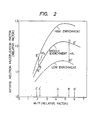
- the infinite neutron multiplication factor of the fuel assembly in which the mean pellet density is lower on the periphery and higher at the central portion, will be compared with the infinite neutron multiplication factor of the fuel assembly which has the enrichment distribution, with reference to Figure 2.
- the ratio M/F on the periphery can be increased from B to B' by reducing the pellet mean density on the periphery of the fuel assembly as compared with the conventional fuel assembly.
- the neutron absorption effect of the water becomes greater on the periphery of the fuel assembly when the ratio M/F increases, whereas the thermal neutrol utilization factor drops.
- the infinite neutron multiplication factor slighly drops from D to D'.
- the ratio M/F drops from C to C' at the central portion, on the contrary, when the pellet mean density is 'increased..As a result, the infinite neutron multiplication factor drops from E to E' in Figure 2 but since the mean neutron energy drops due to inflow of the neutrons thermalized on the periphery of the fuel assembly, the infinite neutron multiplication factor slightly rises, on the contrary. As a result, the drop of the infinite neutron multiplication factor of the fuel assemblies as a whole is limited in comparison with the fuel assembly having uniform enrichment distribution. Since the quantity of the fissionable material is reduced by reducing the pellet mean density on the periphery of the fuel assembly and since the abovementioned effect of the infinite neutron multiplication factor is obtained, the relative fuel rod power can be remarkably reduced.
- the infinite neutron multiplication factor of the fuel assembly having the enrichment distribution changes from D to D" in Figure on the outskirts 2 because the enrichment becomes lower at the central area, on the contrary and rises from E to E" at the central area because the enrichment becomes higher.
- the deceleration ratio ( s / a , where is a mean value of decrement of the energy logarithm per collision and s(a) is the sectional area of macroscopic scattering (absorption)) becomes smaller.
- the change quantity ⁇ k 1 of the infinite neutron multiplication factor with the change of enrichment at the point, where M/F is large becomes greater than the change quantity ⁇ k 2 at the point where M/F is small.
- the infinite neutron multiplication factor of the fuel assemblies as a whole can be increased more greatly by changing the pellet mean density than by chainging the enrichment distribution.
- the fuel assembly obtained in the abovementioned manner can reduce the fuel to be loaded to the core without raising the mean enrichment of the fuel assemblies as a whole and without deteriorating the local output peaking coefficient. It is thus possible to reduce the quantity of natural uranium, the separation work unit (hereinafter abbreviated as "SWU”) and the quantity to be reprocessed.
- SWU separation work unit
- the present invention does not deny the method of generating the mean enrichment distribution and can use conjointly such a method.
- the method can be used especially effectively for the fuel rods at the corners of the fuel assembly.
- the present invention is shown applied to an ordinary 8x8 fuel assembly.
- Figure 9 shows the transverse section of this example.
- the fuel rods 1 those represented by reference numerals 6 through 11 are employed.
- Table 1 shows the enrichment and pellet mean density of each fuel rod.
- Reference numeral 12 represents a water rod.
- Figure 10 shows the transverse section of the conventional fuel assembly.
- fuel rods 13 through 17 shown in Table 2 are employed.
- Reference numeral 18 represents a water rod.
- the pellet mean density is 95% for all the rods.
- Example 1 The mean enrichment is uniform in the fuel assemblies of both Example 1 and Comparative Example 1 and the enrichment at the central area in Example 1 is 0.9 times that in Comparative Example 1.
- Table 3 shows the enrichment and pellet mean density at the central portion and on the periphery for each of Example 1 and Comparative Example 1.
- the infinite neutron multiplication factor at the initial stage- of combustion can be increased by about 0.8% by changing the enrichment ratio between the central area and on the periphery of the fuel assembly from the conventional value 1.4 to 11.
- the derivable burnup can be extended and the assembly output reaches the same value as the conventional value even when the loading uranium quantity is smaller.
- the local output peaking coefficient can be equalized substantially to the conventional value by changing the pellet mean density by 10% between the periphery and the central portion of the fuel assembly.
- Figure 4 shows the loading uranium quantity per unit output, the necessary natural uranium quantity, the SWU, the control rod worth and the void coefficient with those of the conventional values being 1, respectively.
- FIG. 11 shows the transverse section of the fuel assembly of the present invention.
- the fuel rods those represented by reference numerals 19 through 24 are employed.
- the enrichment and pellet mean density of each fuel rod are shown in Table 5. No water rod is used.
- the decrease of the void coefficient and flattening of the local output peaking coefficient are accomplished by reducing the pellet mean density on the periphery of the fuel assembly by 10% as compared with that at the central portion.
- This arrangement makes it possible to replace the water rod, that has conventionally served for this purpose, by the fuel rod.
- the number of fuel assemblies can be reduced by about 4% as compared with Example 1.
- Table 6 shows the loading uranium quantity per unit output, the necessary uranium quantity, the SWU, the control rod worth and the void coefficient in this example with the conventional values being 1.
- This example shows the application of the present invention to a fuel assembly for a high burnup core using a fuel assembly of about 5 wt% enrichment.
- the mean enrichment of the fuel assemblies becomes 5.1 w/o from the enrichment distribution shown in Table 7.
- the enrichment of all the fuel rods is set to 5.lwt% and the pellet mean density is such that the mean value on the periphery is lower by 15% than that at the central area.
- the assembly output can be made the same as that in the case having the enrichment distribution shown in Table 7 without deteriorating the local output peaking factor of the fuel assembly, and the necessary natural uranium quantity per unit output, the uranium quantity and the SWU can be reduced by about 2% (in comparison with the case in which the enrichment distribution exists as shown in Table 7.
- the present invention makes it possible to make the mean enrichment of the fuel assembly maximum. If the enrichment of all the fuel rods is set to the limit value of 5.5 wt%, the derivable burnup can be extended by about 3 GWd/st. This represents the cycle period by about 2 months.
- Table.8 shows the loading uranium quantity per unit output, the necessary natural uranium quantity and the SWU with those of the fuel assembly having the enrichment distribution of Table 7 being 1, respectively.
- the output can be rendered flat by effectively utilizing the nuclear heterogeneity of the fuel assembly so that the uranium resources can be saved while keeping the mean enrichment of the fuel assembly and the local output peaking factor substantially equal to the conventional values. Since the loading uranium quantity can be reduced, the quantity to be reprocessed can be reduced and a core having higher safety can be realized.
- FIG 12 shows the transverse section of the fuel assembly.
- Fuel rods represented by reference numerals 25 through 30 are used as the fuel rods.
- Table 9 shows the enrichment and pellet diameter of each fuel rod. The enrichment of this fuel assembly is determined to be 0.9 times the enrichment at the central portion of the conventional fuel assembly with the mean enrichment being equal to the conventional value.
- the diameter of the fuel rods 27,- 28, 29 on the periphery is reduced by 5% as compared with the diameter of the fuel rods 25, 26, 30 at the central portion (the pellet diameter is also reduced by 5%) so that the ratio of the unit grating water to the pellet sectional area on the outskirts of the fuel assembly is made greater by 21% than that at the central area.
- Table 10 shows the ratio of the mean enrichment on the periphery to the central portion and the ratio of the unit grating water to the pellet sectional area in comparison with the conventional values, respectively.
- Table 11 shows the loading uranium quantity per unit output, the necessary natural uranium quantity, the SWU, the control rod worth and the void coefficient in this example in comparison with the conventional values that are 1, respectively.
Abstract
- (1) The theoretical density of the nuclear fuel material pellets to be inserted into the fuel rod is reduced.
- (2) The nuclear fuel material pellets to be inserted into the fuel rod is made hollow.
- (3) The diameter of the fuel rod is reduced.
Description
- This invention relates to a fuel assembly for a reactor. The fuel assembly consists of a predetermined number of fuel rods that are bundled by a support grating in a group as a handling unit. A predetermined number of fuel assemblies are set up in moderators in the reactor and the gaps between the fuel assemblies are kept so that the fuel assemblies can be individually loaded or withdrawn or control rods can be easily inserted between the fuel assemblies. Accordingly, the fuel rods located on the periphery of the fuel assemblies are surrounded by a greater number of moderators than those located at the central portion. As a result, thermalization of neutrons proceeds effectively on the periphery of fuel assemblies to cause more vigorous nuclear fission, to raise the local output peaking coefficient on the periphery and to reduce thermal allowance. For these reasons, the enrichment gradation(lowering the fuel pellets enrichment on the periphery of the assembly than at the central portion) has been employed in the conventional boiling water reactors in order to equalise the local output peaking factors of the fuel assemblies. However, this method invites the following problems.
- (1) The fissionable material is left unburnt at the central portion of the fuel assembly and hence,'the fuel resources can not be utilized effectively.
- (2) Since the fuel having higher enrichment must be disposed at the central portion of fuel assembly where having smaller importance Lc/ while the fuel having lower enrichment must be disposed on the periphery of the fuel assembly where having greater importance, the infinite neutron multiplication factor of the fuel assemblies as a mean value drops.
- (3) Fuel pellets having higher enrichment than the mean enrichment must be used in order to give the enrichment gradation. This reduces the maximal value of the atomic number of the fissionable material to be packed into the fuel assembly since there exists a limitation to the highest pellet enrichment at present, and reduces the derivable burnup. This is not desirable for a highly burnup core using high enrichment fuel pellets.
- To solve these problems, the present invention is directed to provide fuel assemblies that can effectively burn the fissionable material while equalising the local output peaking factors, can keep the overall output uniform and can effectively consume the fuel resources.
- To accomplish this object, the fuel assembly of the present invention is characterized in that the mean value of the loading quantity of the fissionable material, per unit fuel rod, of the fuel rods of the outermost layer is lowered than that of the other fuel rods.
- The following three methods can be used to reduce the loading quantity of the fissionable material per unit fuel rod.
- (1) The theoretical density of the fuel pellets material to be inserted into the fuel rod is reduced.
- (2) Hollow pellets are used.
- (3) Thinner diameter fuel rods are used.
- The methods (1) and (2), that is, the constructions in which the mean density of the pellets from densification upon burnup that would otherwise occur in carrying out a high level of burnup. The constructions (2) and (3) make it easier to carry out the density control. Since the method (3) reduces the diameter of the cladding tube of the fuel rod, the quantity of the moderator increases as much. Accordingly, the ratio of number of atoms (M/F) between the moderator (M) and the fissionable material (F) can be increased by a slight change.
-
- Figure 1 is a transverse sectional view of the fuel assemblies;
- Figure 2 is a diagram showing.the relation between the infinite neutron multiplication factor and the ratio M/F;
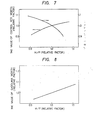
- Figure 3 is a diagram showing the relation between the infinite neutron multiplication factor and the ratio of the smeared density of the pellets at the central portion to the smeared density of the pellets on the periphery;
- Figure 4 is a diagram showing the relation between the relative fuel rod output and the abovementioned ratio of the smeared density;
- Figure 5 is a diagram showing the relation between the infinite neutron multiplication factor and the ratio of the mean enrichment at the central portion to the mean enrichment on the periphery;
- Figure 6 is a diagram showing the relation between the relative fuel rod output and the abovementioned ratio of the mean enrichment;
- Figure 7 is a diagram showing the relation of the control rod worth and the void coefficient versus the ratio H/U;
- Figure 8 is a diagram showing the relation between the value of Gadolinia worth and the ratio H/U;
- Figure 9 is a transverse sectional view of the fuel assembly in accordance with an embodiment of the present invention;
- Figure 10 is a transverse sectional view of the conventional fuel assembly for the sake of comparison; and
- Figure 11 is a transverse sectional view of the fuel assembly in accordance with another embodiment of the present invention.
- Hereinafter, the present invention will be described with reference to a boiling water reactor by way of example.
- As shown in Figure 1, in the boiling water reactor, each fuel assembly consists of a group of
fuel rods 1 aggregated within a predetermined range encompassed by a coolant of the core or anunderwater channel box 2 and is loaded. Acontrol rod 4 or a neutrondetector fitting pipe 5 is disposed outside thechannel box 2. The gap between thefuel assemblies 3 is kept so that the device such as thecontrol rod 4 can be inserted. The periphery of the fuel assembly is filled with the cooling water. In this case, thefuel rods 1 positioned on the periphery of thefuel assembly 3 are surrounded with a greater quantity of water than those positioned at the central position of thefuel assembly 3. As a result, the following nuclearly heterogeneous effects (i) and (ii) occur between the periphery portion and the central portion of thefuel assembly 3. - (i) Thermalization of neutron proceeds effectively around the fuel assembly where a greater amount of water as the moderator of the neutron exists. Hence, the number of thermal neutrons becomes greater at these portions than at the central portion.
- (ii) In consequence, differences occur in the mean neutron energy and in the infinite neutron multiplication factor between the periphery portions and central portion of the fuel assembly. As shown in Figure 2, as the position approaches closer to the periphery portions of the fuel assembly, that is, as the ratio of atomic numbers (.M/F) of the moderator (M) to the fissionable material (.F) increases, the infinite neutron multiplication factor increases gradually and after passing a predetermined peak, it decreases gradually. This is because the water provides the advantage that it promotes deceleration of neutrons to improve the infinite multiplication factor as well as the disadvantage of convergence. The practical fuel assembly is designed so that the void coefficient is always negative. Hence, the point A of Figure 2 is used as the mean M/F of the fuel assemblies. However, the operation is effected at the point B, which is an over- deceleration range, on the periphery of the fuel assembly whereas the operation is effected at the point C, which is an insufficient deceleration range, at the central portion of the fuel assembly. Accordingly, the infinite neutron multiplication factor is greater at the central area of the fuel assembly.
- In accordance with the present invention, the mean value of the loading quantity of the fissionable material, per fuel rod, of the fuel rods on the periphery of the fuel assembly is made smaller than that at the central portion of the fuel assembly.
- Figure 3 shows the relation between the infinite neutron multiplication factor and the ratio of the smeared density of pellets at the central portion to the smeared density of pellets at the periphery when both loading quantity and mean enrichment of the fuel material are kept constant and Figure 4 shows the relation between the relative fuel rod power and the same ratio under the same condition as above.
- For the sake of comparison, Figure 5 shows the relation between the infinite neutron multiplication factor and the ratio of the mean enrichment at the central portion to the mean enrichment at the periphery and Figure 6 shows the relation between the relative fuel rod output and the abovementioned ratio, using the ratio of the mean enrichment at the central portion to that on the periphery as a parameter, respectively.
- The infinite neutron multiplication factor of the fuel assembly, in which the mean pellet density is lower on the periphery and higher at the central portion, will be compared with the infinite neutron multiplication factor of the fuel assembly which has the enrichment distribution, with reference to Figure 2. The ratio M/F on the periphery can be increased from B to B' by reducing the pellet mean density on the periphery of the fuel assembly as compared with the conventional fuel assembly. As is obvious from this diagram, the neutron absorption effect of the water becomes greater on the periphery of the fuel assembly when the ratio M/F increases, whereas the thermal neutrol utilization factor drops. As a result, the infinite neutron multiplication factor slighly drops from D to D'. On the other hand, the ratio M/F drops from C to C' at the central portion, on the contrary, when the pellet mean density is 'increased..As a result, the infinite neutron multiplication factor drops from E to E' in Figure 2 but since the mean neutron energy drops due to inflow of the neutrons thermalized on the periphery of the fuel assembly, the infinite neutron multiplication factor slightly rises, on the contrary. As a result, the drop of the infinite neutron multiplication factor of the fuel assemblies as a whole is limited in comparison with the fuel assembly having uniform enrichment distribution. Since the quantity of the fissionable material is reduced by reducing the pellet mean density on the periphery of the fuel assembly and since the abovementioned effect of the infinite neutron multiplication factor is obtained, the relative fuel rod power can be remarkably reduced.
- On the other hand, the infinite neutron multiplication factor of the fuel assembly having the enrichment distribution changes from D to D" in Figure on the
outskirts 2 because the enrichment becomes lower at the central area, on the contrary and rises from E to E" at the central area because the enrichment becomes higher. When the enrichment becomes higher, the deceleration ratio (s/ a, where
 is a mean value of decrement of the energy logarithm per collision and
 s(a) is the sectional area of macroscopic scattering (absorption)) becomes smaller. The change quantity Δk1 of the infinite neutron multiplication factor with the change of enrichment at the point, where M/F is large, becomes greater than the change quantity Δk2 at the point where M/F is small. As a result, the infinite neutron multiplication factor of the fuel assemblies as a whole can be increased more greatly by changing the pellet mean density than by chainging the enrichment distribution.
- Since the mean M/F of the fuel assemblies as a whole can be increased by reducing the pellet mean density on the outskirts portions, the neutron mean energy drops so that both values of control rod worth and Gadolinia worth can be increased while the output coefficient can be reduced. This is effective for a high combustion core using a high enrichment fuel and also makes it possible to realize a stable core in the conventional cores. Figures 7 and 8 show the relation between the ratio M/F and the value of control rod worth and between the ratio M/F and the value of Gadolinia worth, respectively.
- .The fuel assembly obtained in the abovementioned manner can reduce the fuel to be loaded to the core without raising the mean enrichment of the fuel assemblies as a whole and without deteriorating the local output peaking coefficient. It is thus possible to reduce the quantity of natural uranium, the separation work unit (hereinafter abbreviated as "SWU") and the quantity to be reprocessed.
- The present invention does not deny the method of generating the mean enrichment distribution and can use conjointly such a method. The method can be used especially effectively for the fuel rods at the corners of the fuel assembly.
- Hereinafter, embodiments of the present invention will be described definitely.
- In this example, the present invention is shown applied to an ordinary 8x8 fuel assembly. Figure 9 shows the transverse section of this example. As the
fuel rods 1, those represented byreference numerals 6 through 11 are employed. Table 1 shows the enrichment and pellet mean density of each fuel rod.Reference numeral 12 represents a water rod.
- Figure 10 shows the transverse section of the conventional fuel assembly. In this case,
fuel rods 13 through 17 shown in Table 2 are employed.Reference numeral 18 represents a water rod. In this example, the pellet mean density is 95% for all the rods. - The mean enrichment is uniform in the fuel assemblies of both Example 1 and Comparative Example 1 and the enrichment at the central area in Example 1 is 0.9 times that in Comparative Example 1. Table 3 shows the enrichment and pellet mean density at the central portion and on the periphery for each of Example 1 and Comparative Example 1.


- The infinite neutron multiplication factor at the initial stage- of combustion can be increased by about 0.8% by changing the enrichment ratio between the central area and on the periphery of the fuel assembly from the conventional value 1.4 to 11. As a result, the derivable burnup can be extended and the assembly output reaches the same value as the conventional value even when the loading uranium quantity is smaller. On the other hand, the local output peaking coefficient can be equalized substantially to the conventional value by changing the pellet mean density by 10% between the periphery and the central portion of the fuel assembly. Figure 4 shows the loading uranium quantity per unit output, the necessary natural uranium quantity, the SWU, the control rod worth and the void coefficient with those of the conventional values being 1, respectively.

- This example also shows the application of the present invention to an ordinary fuel assembly. Figure 11 shows the transverse section of the fuel assembly of the present invention. As the fuel rods, those represented by
reference numerals 19 through 24 are employed. The enrichment and pellet mean density of each fuel rod are shown in Table 5. No water rod is used.
- In this example, the decrease of the void coefficient and flattening of the local output peaking coefficient are accomplished by reducing the pellet mean density on the periphery of the fuel assembly by 10% as compared with that at the central portion. This arrangement makes it possible to replace the water rod, that has conventionally served for this purpose, by the fuel rod. As a result, the number of fuel assemblies can be reduced by about 4% as compared with Example 1. Table 6 shows the loading uranium quantity per unit output, the necessary uranium quantity, the SWU, the control rod worth and the void coefficient in this example with the conventional values being 1.

- This example shows the application of the present invention to a fuel assembly for a high burnup core using a fuel assembly of about 5 wt% enrichment. In the case of the fuel assembly in which the maximum enrichment of the pellet used is limited to 5.5 wt%, the mean enrichment of the fuel assemblies becomes 5.1 w/o from the enrichment distribution shown in Table 7.
-

- It can be understood from the foregoing examples that even when the pellet enrichment is only one kind, the local output peaking factor can be made the same as the conventional value. If there is a limit to the maximum enrichment of the pellet used, therefore, the present invention makes it possible to make the mean enrichment of the fuel assembly maximum. If the enrichment of all the fuel rods is set to the limit value of 5.5 wt%, the derivable burnup can be extended by about 3 GWd/st. This represents the cycle period by about 2 months. Table.8 shows the loading uranium quantity per unit output, the necessary natural uranium quantity and the SWU with those of the fuel assembly having the enrichment distribution of Table 7 being 1, respectively.

- As described in the foregoing, by the simple method of reducing the mean value of the pellet mean density on the periphery to the value lower than that at the central portion, the output can be rendered flat by effectively utilizing the nuclear heterogeneity of the fuel assembly so that the uranium resources can be saved while keeping the mean enrichment of the fuel assembly and the local output peaking factor substantially equal to the conventional values. Since the loading uranium quantity can be reduced, the quantity to be reprocessed can be reduced and a core having higher safety can be realized.
- Next, the fuel assemblies having the aforementioned constructions (2) and (3), in which the ratio of the sectional area of pellet to the unit grating moderator is smaller on the periphery than at the central portion, will be described.
- Figure 12 shows the transverse section of the fuel assembly. Fuel rods represented by
reference numerals 25 through 30 are used as the fuel rods. Table 9 shows the enrichment and pellet diameter of each fuel rod. The enrichment of this fuel assembly is determined to be 0.9 times the enrichment at the central portion of the conventional fuel assembly with the mean enrichment being equal to the conventional value. The diameter of thefuel rods 27,- 28, 29 on the periphery is reduced by 5% as compared with the diameter of thefuel rods 

- As a result, the local output peaking can be made equal to the conventional value but the derivable burnup can be enhanced by about 5%. Table 11 shows the loading uranium quantity per unit output, the necessary natural uranium quantity, the SWU, the control rod worth and the void coefficient in this example in comparison with the conventional values that are 1, respectively.

Accordingly, if the enrichment of the fuel rods inside a given fuel assembly is made uniform, the nuclear fission reaction occurs more vigorously on the periphery of the fuel assembly, thus elevating the local output peaking coefficient on the periphery and reducing the thermal allowance.
Claims (6)
Applications Claiming Priority (4)
| Application Number | Priority Date | Filing Date | Title |
|---|---|---|---|
| JP56072351A JPS57187687A (en) | 1981-05-15 | 1981-05-15 | Fuel assembly |
| JP72351/81 | 1981-05-15 | ||
| JP112179/81 | 1981-07-20 | ||
| JP56112179A JPS5814080A (en) | 1981-07-20 | 1981-07-20 | Fuel assembly |
Publications (2)
| Publication Number | Publication Date |
|---|---|
| EP0065697A1 true EP0065697A1 (en) | 1982-12-01 |
| EP0065697B1 EP0065697B1 (en) | 1985-09-11 |
Family
ID=26413485
Family Applications (1)
| Application Number | Title | Priority Date | Filing Date |
|---|---|---|---|
| EP82104077A Expired EP0065697B1 (en) | 1981-05-15 | 1982-05-11 | Fuel assembly |
Country Status (3)
| Country | Link |
|---|---|
| US (1) | US4689195A (en) |
| EP (1) | EP0065697B1 (en) |
| DE (1) | DE3266144D1 (en) |
Cited By (6)
| Publication number | Priority date | Publication date | Assignee | Title |
|---|---|---|---|---|
| EP0086427A1 (en) * | 1982-02-08 | 1983-08-24 | Hitachi, Ltd. | Fuel assembly for boiling water reactor |
| US4689195A (en) * | 1981-05-15 | 1987-08-25 | Hitachi, Ltd. | Fuel assembly |
| US4708845A (en) * | 1985-10-18 | 1987-11-24 | Westinghouse Electric Corp. | BWR fuel assembly with improved spacer and fuel bundle design for enhanced thermal-hydraulic performance |
| EP0319744A2 (en) * | 1987-12-07 | 1989-06-14 | Westinghouse Electric Corporation | Fuel-rod mini-bundle for use in a BWR fuel assembly |
| US5176877A (en) * | 1989-09-22 | 1993-01-05 | Hitachi, Ltd. | Nuclear fuel assembly and nuclear reactor core containing said assembly |
| US6347130B1 (en) * | 1994-12-23 | 2002-02-12 | Westinghouse Atom Ab | Fuel assembly with short fuel units |
Families Citing this family (5)
| Publication number | Priority date | Publication date | Assignee | Title |
|---|---|---|---|---|
| US6181762B1 (en) | 1997-03-28 | 2001-01-30 | General Electric Company | Nuclear fuel bundle having different peak power limits |
| FR2863097B1 (en) * | 2003-11-27 | 2008-05-02 | Framatome Anp | FUEL ASSEMBLY FOR PRESSURIZED WATER NUCLEAR REACTOR CONTAINING URANIUM ENRICHED WITHOUT PLUTONIUM. |
| WO2008137762A2 (en) * | 2007-05-04 | 2008-11-13 | Cedars-Sinai Medical Center | Methods of diagnosis and treatment of crohn's disease |
| JP5361964B2 (en) * | 2011-08-31 | 2013-12-04 | 日立Geニュークリア・エナジー株式会社 | Initial loading core of nuclear reactor |
| JP6633471B2 (en) * | 2016-08-01 | 2020-01-22 | 株式会社東芝 | REACTOR AND HEAT REMOVAL METHOD FOR REACTOR |
Citations (8)
| Publication number | Priority date | Publication date | Assignee | Title |
|---|---|---|---|---|
| FR1312193A (en) * | 1961-12-27 | 1962-12-14 | Gen Electric | Fuel assembly for nuclear reactor |
| DE1814641A1 (en) * | 1967-12-15 | 1969-07-24 | Gen Electric | Fuel assembly for plutonium nuclear reactor |
| US3652744A (en) * | 1969-11-19 | 1972-03-28 | Atomic Energy Commission | Method of making nuclear fuel elements |
| US3844886A (en) * | 1968-05-02 | 1974-10-29 | Gen Electric | Nuclear reactor utilizing plutonium in peripheral fuel assemblies |
| JPS529792A (en) * | 1975-07-15 | 1977-01-25 | Hitachi Ltd | Fuel assembly |
| DE2742939A1 (en) * | 1976-09-25 | 1978-03-30 | Hitachi Ltd | FUEL ARRANGEMENT |
| DE2742940A1 (en) * | 1976-09-25 | 1978-03-30 | Hitachi Ltd | CORE REACTOR CORE STRUCTURE |
| JPS53109089A (en) * | 1977-03-03 | 1978-09-22 | Toshiba Corp | Fuel assembly |
Family Cites Families (8)
| Publication number | Priority date | Publication date | Assignee | Title |
|---|---|---|---|---|
| BE597707A (en) * | 1959-12-11 | |||
| DE2236780A1 (en) * | 1972-07-26 | 1974-02-07 | Siemens Ag | PROCEDURE FOR BUILDING AND OPERATING AT LEAST TWO NUCLEAR REACTORS |
| US4059484A (en) * | 1975-05-02 | 1977-11-22 | Exxon Nuclear Company, Inc. | Hybrid nuclear fuel assembly with reduced linear heat generation rates |
| JPS54121389A (en) * | 1978-03-13 | 1979-09-20 | Hitachi Ltd | Fuel assembly |
| JPS5572891A (en) * | 1978-11-29 | 1980-06-02 | Hitachi Ltd | Reactor core structure |
| JPS5774689A (en) * | 1980-10-29 | 1982-05-10 | Hitachi Ltd | Fuel assembly |
| DE3266144D1 (en) * | 1981-05-15 | 1985-10-17 | Hitachi Ltd | Fuel assembly |
| JPS6013283A (en) * | 1983-07-04 | 1985-01-23 | 株式会社東芝 | Boiling water reactor |
-
1982
- 1982-05-11 DE DE8282104077T patent/DE3266144D1/en not_active Expired
- 1982-05-11 EP EP82104077A patent/EP0065697B1/en not_active Expired
-
1984
- 1984-07-30 US US06/635,927 patent/US4689195A/en not_active Expired - Fee Related
Patent Citations (8)
| Publication number | Priority date | Publication date | Assignee | Title |
|---|---|---|---|---|
| FR1312193A (en) * | 1961-12-27 | 1962-12-14 | Gen Electric | Fuel assembly for nuclear reactor |
| DE1814641A1 (en) * | 1967-12-15 | 1969-07-24 | Gen Electric | Fuel assembly for plutonium nuclear reactor |
| US3844886A (en) * | 1968-05-02 | 1974-10-29 | Gen Electric | Nuclear reactor utilizing plutonium in peripheral fuel assemblies |
| US3652744A (en) * | 1969-11-19 | 1972-03-28 | Atomic Energy Commission | Method of making nuclear fuel elements |
| JPS529792A (en) * | 1975-07-15 | 1977-01-25 | Hitachi Ltd | Fuel assembly |
| DE2742939A1 (en) * | 1976-09-25 | 1978-03-30 | Hitachi Ltd | FUEL ARRANGEMENT |
| DE2742940A1 (en) * | 1976-09-25 | 1978-03-30 | Hitachi Ltd | CORE REACTOR CORE STRUCTURE |
| JPS53109089A (en) * | 1977-03-03 | 1978-09-22 | Toshiba Corp | Fuel assembly |
Cited By (7)
| Publication number | Priority date | Publication date | Assignee | Title |
|---|---|---|---|---|
| US4689195A (en) * | 1981-05-15 | 1987-08-25 | Hitachi, Ltd. | Fuel assembly |
| EP0086427A1 (en) * | 1982-02-08 | 1983-08-24 | Hitachi, Ltd. | Fuel assembly for boiling water reactor |
| US4708845A (en) * | 1985-10-18 | 1987-11-24 | Westinghouse Electric Corp. | BWR fuel assembly with improved spacer and fuel bundle design for enhanced thermal-hydraulic performance |
| EP0319744A2 (en) * | 1987-12-07 | 1989-06-14 | Westinghouse Electric Corporation | Fuel-rod mini-bundle for use in a BWR fuel assembly |
| EP0319744A3 (en) * | 1987-12-07 | 1990-01-31 | Westinghouse Electric Corporation | Fuel-rod mini-bundle for use in a bwr fuel assembly |
| US5176877A (en) * | 1989-09-22 | 1993-01-05 | Hitachi, Ltd. | Nuclear fuel assembly and nuclear reactor core containing said assembly |
| US6347130B1 (en) * | 1994-12-23 | 2002-02-12 | Westinghouse Atom Ab | Fuel assembly with short fuel units |
Also Published As
| Publication number | Publication date |
|---|---|
| US4689195A (en) | 1987-08-25 |
| DE3266144D1 (en) | 1985-10-17 |
| EP0065697B1 (en) | 1985-09-11 |
Similar Documents
| Publication | Publication Date | Title |
|---|---|---|
| US4587090A (en) | Fuel assembly for boiling water reactor | |
| US5349618A (en) | BWR fuel assembly having oxide and hydride fuel | |
| EP0065697A1 (en) | Fuel assembly | |
| US5337337A (en) | Fuel assembly | |
| Goldstein et al. | A comparison of gadolinia and boron for burnable poison applications in pressurized water reactors | |
| US4652427A (en) | Fuel assembly | |
| US3252867A (en) | Long lifetime nuclear reactor | |
| US3267002A (en) | Method for controlling a nuclear reactor | |
| EP0093901B1 (en) | High uranium utilization fuel rod for light water reactors | |
| US4587089A (en) | Fuel assembly for boiling water reactor | |
| JPS6129478B2 (en) | ||
| EP0447108B1 (en) | Fuel assembly and nuclear reactor | |
| EP0051441A1 (en) | Nuclear reactor and fuel assembly therefor | |
| US5347550A (en) | Core of light-water reactor | |
| JP3241071B2 (en) | Light water reactor core | |
| JPH04357493A (en) | Structure of fuel assembly | |
| JPS60201284A (en) | Fuel aggregate | |
| JPS6361990A (en) | Fuel aggregate | |
| JPS59147295A (en) | Fuel assembly | |
| JPS6151275B2 (en) | ||
| JPH02232595A (en) | Fuel loading of boiling nuclear reactor | |
| US3364119A (en) | Zoned fuel fast reactors | |
| JPS63172990A (en) | Nuclear-reactor fuel aggregate | |
| JPS5824886A (en) | Bwr type reactor | |
| JPS6249946B2 (en) |
Legal Events
| Date | Code | Title | Description |
|---|---|---|---|
| PUAI | Public reference made under article 153(3) epc to a published international application that has entered the european phase |
Free format text: ORIGINAL CODE: 0009012 |
|
| AK | Designated contracting states |
Designated state(s): CH DE FR GB IT NL SE |
|
| 17P | Request for examination filed |
Effective date: 19830214 |
|
| ITF | It: translation for a ep patent filed |
Owner name: MODIANO & ASSOCIATI S.R.L. |
|
| GRAA | (expected) grant |
Free format text: ORIGINAL CODE: 0009210 |
|
| AK | Designated contracting states |
Designated state(s): CH DE FR GB IT LI NL SE |
|
| REF | Corresponds to: |
Ref document number: 3266144 Country of ref document: DE Date of ref document: 19851017 |
|
| ET | Fr: translation filed | ||
| PLBE | No opposition filed within time limit |
Free format text: ORIGINAL CODE: 0009261 |
|
| STAA | Information on the status of an ep patent application or granted ep patent |
Free format text: STATUS: NO OPPOSITION FILED WITHIN TIME LIMIT |
|
| 26N | No opposition filed | ||
| ITTA | It: last paid annual fee | ||
| PGFP | Annual fee paid to national office [announced via postgrant information from national office to epo] |
Ref country code: GB Payment date: 19940429 Year of fee payment: 13 |
|
| PGFP | Annual fee paid to national office [announced via postgrant information from national office to epo] |
Ref country code: SE Payment date: 19940506 Year of fee payment: 13 |
|
| PGFP | Annual fee paid to national office [announced via postgrant information from national office to epo] |
Ref country code: FR Payment date: 19940516 Year of fee payment: 13 |
|
| PGFP | Annual fee paid to national office [announced via postgrant information from national office to epo] |
Ref country code: NL Payment date: 19940531 Year of fee payment: 13 |
|
| PGFP | Annual fee paid to national office [announced via postgrant information from national office to epo] |
Ref country code: CH Payment date: 19940722 Year of fee payment: 13 |
|
| EAL | Se: european patent in force in sweden |
Ref document number: 82104077.1 |
|
| PG25 | Lapsed in a contracting state [announced via postgrant information from national office to epo] |
Ref country code: GB Effective date: 19950511 |
|
| PG25 | Lapsed in a contracting state [announced via postgrant information from national office to epo] |
Ref country code: SE Effective date: 19950512 |
|
| PG25 | Lapsed in a contracting state [announced via postgrant information from national office to epo] |
Ref country code: LI Effective date: 19950531 Ref country code: CH Effective date: 19950531 |
|
| PG25 | Lapsed in a contracting state [announced via postgrant information from national office to epo] |
Ref country code: NL Effective date: 19951201 |
|
| GBPC | Gb: european patent ceased through non-payment of renewal fee |
Effective date: 19950511 |
|
| REG | Reference to a national code |
Ref country code: CH Ref legal event code: PL |
|
| NLV4 | Nl: lapsed or anulled due to non-payment of the annual fee |
Effective date: 19951201 |
|
| EUG | Se: european patent has lapsed |
Ref document number: 82104077.1 |
|
| PG25 | Lapsed in a contracting state [announced via postgrant information from national office to epo] |
Ref country code: FR Effective date: 19960229 |
|
| REG | Reference to a national code |
Ref country code: FR Ref legal event code: ST |
|
| REG | Reference to a national code |
Ref country code: FR Ref legal event code: ST |
|
| PGFP | Annual fee paid to national office [announced via postgrant information from national office to epo] |
Ref country code: DE Payment date: 19970729 Year of fee payment: 16 |
|
| PG25 | Lapsed in a contracting state [announced via postgrant information from national office to epo] |
Ref country code: DE Free format text: LAPSE BECAUSE OF NON-PAYMENT OF DUE FEES Effective date: 19990302 |